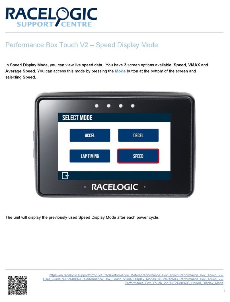
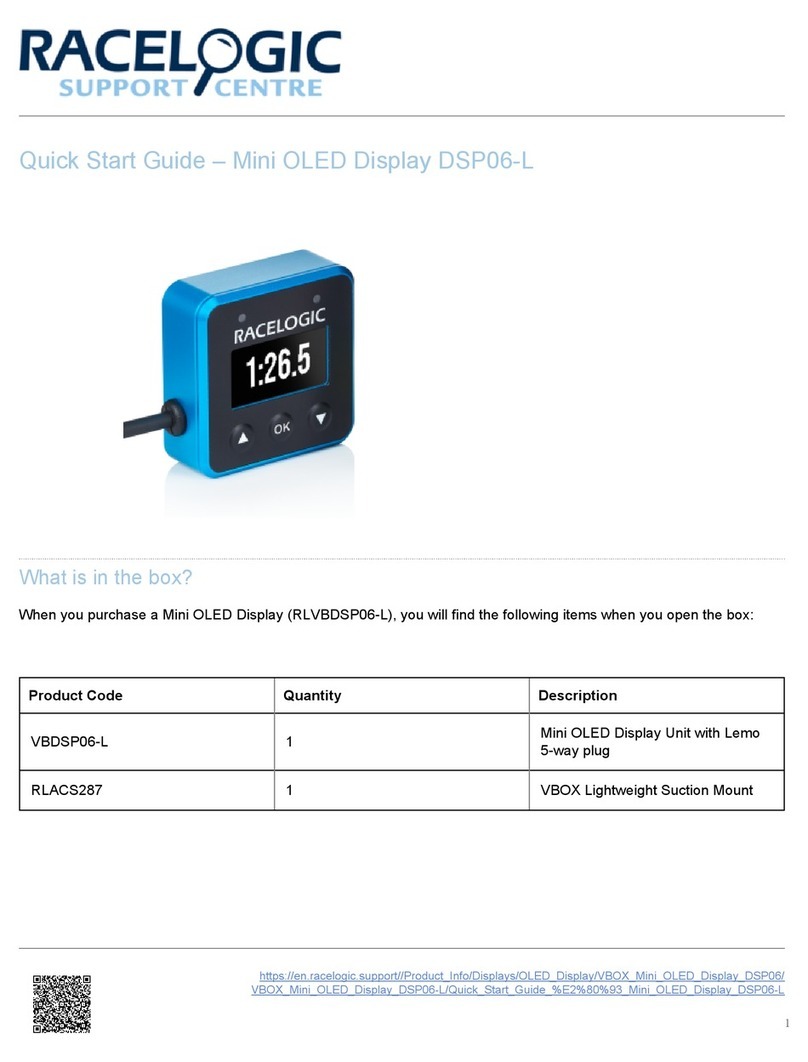
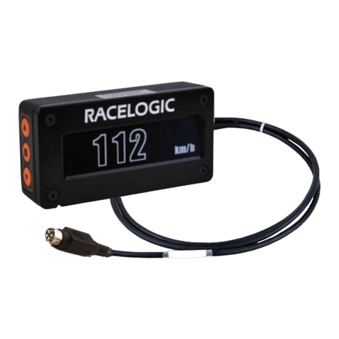
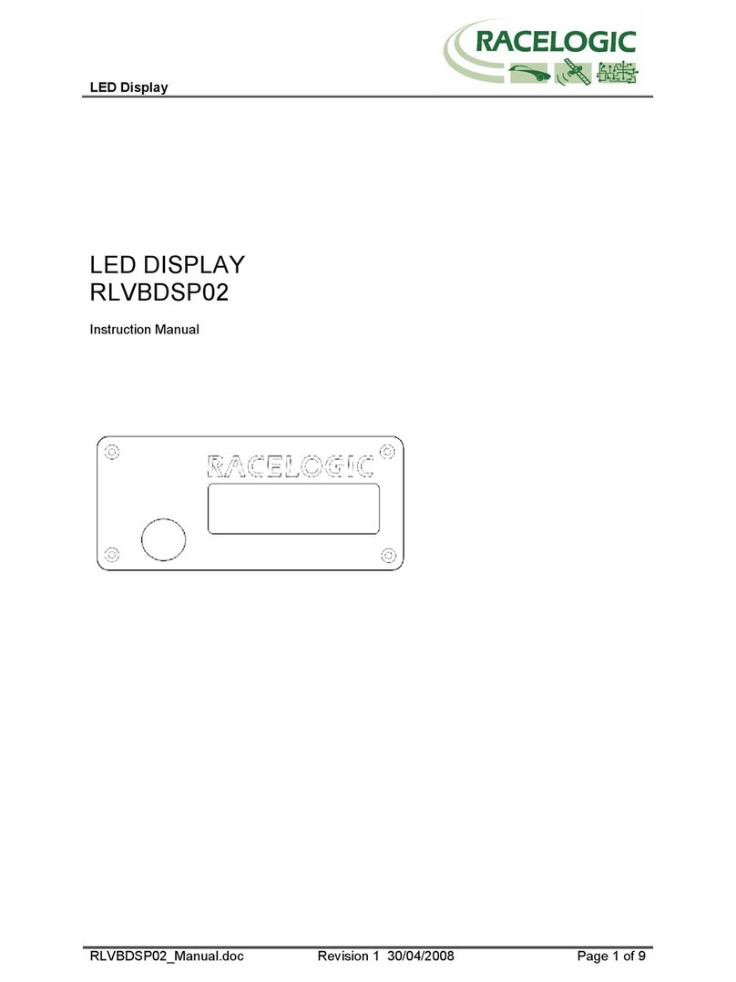
Racelogic RLVBDSP03-24 User manual

Multi- unction Display User Manual
•01 - M D Introduction
•02 - M D Test screens
•03 - M D Data Display Options
•04 - M D Menu Options
•05 - M D Setup (VBOX Tools)
•06 - M D Display Parameter Tables
•07 - M D Thermal Printer
•08 - M D irmware Upgrade
•09 - M D CAN Output
•10 - M D PIN OUTS
•11 - M D Technical Specifications
•12 - M D Standard Inventory and Accessories
•Home
1

01 - M D Introduction
eatures
• Display multiple data parameters at one time
• Backlit large character display
• User selectable display parameters
• ¼ - 20 Thread mounting
Inputs/Outputs
Connection to VBOX
The Multi- unction Display has 2 LEMO connectors at each end. The top left and top right connectors share the same
function and are used for connection to the VBOX CAN bus and to supply power to the display. The bottom left and
bottom right connectors are serial connections. The function of these connectors is to allow firmware upgrade via a PC
and to provide connection to a thermal printer for instant paper record of test results. Also in the serial connectors is a
digital output, which will either send a pulse or toggle its state when a split line is crossed.
https://racelogic.support/01VBOX_Automotive/06Displays/Multi- unction_Display_(M D)/
2

Basic Operation
Three buttons are used to configure the display.
The left and right arrow keys are used for selecting a menu item or cycling through the display screens. When power is
applied, the display will revert to the data display mode.
https://racelogic.support/01VBOX_Automotive/06Displays/Multi- unction_Display_(M D)/
3

How to select a Parameter
1. Main screen displayed – press OK.
2. Press right arrow so the display shows ‘SET
PARAMETERS’. Press OK.
3. Press right arrow until the parameter to be altered is
displayed. Press OK.
4. Using right arrow, select either general, brake, accel
or CAN parameters. Press OK to select.
5. The code to be changed should now be flashing. Use
the arrow key to select the new parameter. Press OK to
set. The M display will beep to indicate setting change
has been successful.
6. Press the left arrow button until the display shows
BACK. Press OK. Repeat this step once more to return
to the main screen.
Mounting
The M display is supplied with a windscreen suction mount. This can be connected using the ¼ 20 fitting on the rear
side of the display. Make sure the hole on the rear of the display that is used for the buzzer is not obstructed.
Note: Exposing the windscreen mount to large changes in temperature over a prolonged period of time may cause loss
of suction. We would recommend that the suction mount is removed when the days testing is complete.
https://racelogic.support/01VBOX_Automotive/06Displays/Multi- unction_Display_(M D)/
4
02 - M D Test screens
Pre-set test screens
The eight pre-set test screens allow the user to set up eight individual test profiles that can be accessed directly and
quickly when testing a vehicle. The test that is displayed on the screen will be the test that is being conducted. At the
end of each test the time and distance for the test is displayed and printed on a thermal printer if connected. The results
of the test are also output on the CAN bus.
When you scroll to a new test the test name and start and end conditions are momentarily displayed, then the screen
shows three parameters, Velocity, Time and Distance.
Pre test setup
rom any one of the eight Pre-set Test screens press OK to enter the Set up screens for the Pre-set test.
Press OK to clear the current results of this Pre-set test.
Press OK to clear the results from all of the Pre-set
tests.
Press OK to print all of the results from all of the Pre-set
tests on a Thermal Printer connected to the serial port of
the M D.
Press OK to enter the general Pre-set test setup
screens.
https://racelogic.support/01VBOX_Automotive/06Displays/Multi- unction_Display_(M D)/
5

Press OK to return to the main menu
Entering the Setup menu from any of the pre-set tests will enter the general setup menu from which each of the pre-set
tests can be configured. The Pre-set test numbers are shown on the screen, use the arrow buttons to scroll to the Pre-
set screen you wish to edit then press OK to edit the test details.
Use the left and right arrow keys to scroll through an
alphanumeric list, then press OK to confirm and proceed
to the next character, up to 10 characters.
Press OK choose between ENABLED and DISABLED.
With ENABLED selected all tests will start with a brake
trigger event.
Press OK to edit the Start speed for the test.
Press OK to edit the End speed for the test.
Press OK to edit the distance over which the test should
be timed.
Press OK to return to the main menu
https://racelogic.support/01VBOX_Automotive/06Displays/Multi- unction_Display_(M D)/
6

03 - M D Data Display Options
When power is first applied to the display, it will revert to the last screen displayed. Then pressing one of the arrow keys
in this mode will cycle through the 13 screen layouts. Some screens will display a title page, which will timeout after
approximately one second if no buttons are pressed. The title pages are to inform the user as to which page is
displayed, as shown in the examples below.
https://racelogic.support/01VBOX_Automotive/06Displays/Multi- unction_Display_(M D)/
7

Mode Screens
The different mode screens are as shown below (default setup).
Display Parameters
When viewing data Main screen 1 or 2, the user can configure the display to show either four or two parameters
simultaneously.
If four parameters are displayed at once, a two digit code is shown next to each section of channel data. A list of all the
parameter codes used by the M Display can be found on page 06 - M D Display parameter tables.
If only two parameters are displayed, then the complete description of the channel will be displayed alongside the value,
as shown above.
The setting to change between parameter configurations can be found in CONFIG DISPLAY > NUM OF PARAMS.
https://racelogic.support/01VBOX_Automotive/06Displays/Multi- unction_Display_(M D)/
8

The parameters are split into 4 groups: General, Brake, Accel and CAN. General parameters are taken from standard
Racelogic CAN output from the VBOX. Brake parameters are commonly used in brake testing, the majority of which
require the use of a brake trigger switch with the VBOX. Accel parameters are used in acceleration tests, and CAN
parameters are from external modules connected to a CAN bus, such as analogue, thermocouple or vehicle CAN data.
https://racelogic.support/01VBOX_Automotive/06Displays/Multi- unction_Display_(M D)/
9

04 - M D Menu Options
Enter the main menu by pressing the OK button when in either of the main screen displays. When the desired option to
configure is highlighted, press the OK again to move into to the next sub-menu or setup area. Each menu layer will have
a BACK option. Pressing OK when this is highlighted will exit the currently selected sub-menu.
Main Menu
Define the displayed parameters in both main screens.
Settings such as Contrast, Backlight brightness and
units of measurement.
View the display firmware version and serial number.
View the current compact flash file name, memory %
used and logging status.
Press OK to return to the data display mode.
https://racelogic.support/01VBOX_Automotive/06Displays/Multi- unction_Display_(M D)/
10

Set Parameters Menu
Press OK to select a field to edit. Use the right arrow key
to choose from General, Brake, Accel or CAN. When the
letters are flashing, the arrow keys will cycle through the
parameter list. Press OK to store.
If the parameter indication letters are not flashing, the
right arrow key moves to the next parameter on the
display.
The 2 indicates that the field being edited is on main
screen 2.
Press OK to return to the main menu.
Config Display Menu
Adjust brightness of the backlight. Adjust the brightness
using the arrow keys, press OK to set.
Change the contrast of the LCD. Adjust the contrast
using the arrow keys and press OK to set.
Select measurement units. When units are flashing, the
arrow keys switch between Kmh & Mph.
https://racelogic.support/01VBOX_Automotive/06Displays/Multi- unction_Display_(M D)/
11

Change the display menu language. Select using arrow
keys and press OK to set.
Select the CAN BAUD RATE. Options available are
125Kbs, 250Kb/s, 500Kbps and 1Mbps. Note 500Kbps
is the default VBOX baud rate.
Change the number of parameters shown in the main
screens. Use the arrow keys to select either two or four.
Press OK to enable/disable for firmware upgrades. After
upgrade is complete, status must be manually disabled.
If using a thermal printer, this must be disconnected
before firmware upgrade status is enabled.
Select accel or decel test and set start & end speeds for
each test. Arrow keys increase/decrease the value, OK
key moves to next digit. Target distance can also be
defined here.
OK will reset Average Velocity and the Distance
Travelled. Note, Average Velocity is calculated from
VBOX turn on and not from first movement.
Define a velocity at which the M D will momentarily
beep.
Enable/disable on screen Brake Trigger message when
the Brake Trigger is pressed.
https://racelogic.support/01VBOX_Automotive/06Displays/Multi- unction_Display_(M D)/
12

When enabled, the display will display test results until
another test is completed.
Define up to four distances for drive by noise testing.
When these are crossed the display will beep.
Version Menu
Hardware Version
irmware version.
Unit serial number.
Press OK to return to the main menu.
https://racelogic.support/01VBOX_Automotive/06Displays/Multi- unction_Display_(M D)/
13

Target Set-Up Menu
Press OK to change the target parameter. Press the
right arrow key to choose parameter group, once
selected, arrow keys will cycle through list. Press OK to
store the setting for the target parameter.
Here the target buzzer can be turned on or off. The
target buzzer sounds when the target screen is shown
and the target value is exceeded. The further the value
goes over the target the louder the buzzer becomes.
To set, use the arrow keys to set each digit and the OK
key to move onto the next digit. To set a negative value
the ‘-‘sign must be in the left most digit.
Set using same method as target minimum. The target
value will be at 50% of the full scale. I.e. if a minimum
value of 0 is entered and a target value of 20, the
maximum value will auto set to 40.
Lap Timing Menu
The setup method is the same as the other screens
except from here you can only select lap parameters.
In lap setup, start/finish and split lines can be set. Use
the arrow keys to scroll to which line you wish to set,
drive over the line position and press OK.
To view lap times, press OK. Use arrow keys to move
through the list. When the start / finish line is crossed, a
new lap is stored. Lap times are saved when the M D is
turned off. Power up resets the lap counter to lap 1, so
any previously stored times will be overwritten when new
laps are completed.
https://racelogic.support/01VBOX_Automotive/06Displays/Multi- unction_Display_(M D)/
14

Press OK to print out the lap times for the last 20 laps
stored in EEPROM.
Clear all saved lap times and reset lap counter to lap 1.
On power up the lap index is reset but old lap times are
not cleared to allow old lap times to be viewed after the
event.
Press OK to clear all start / finish and split lines stored in
memory.
Change whether split time is time from start / finish line
(ON) or time from previous split point (O ).
Change whether digital output pulses or toggles when
crossing a start / finish split line.
Press OK to reset average lap time and lap count.
https://racelogic.support/01VBOX_Automotive/06Displays/Multi- unction_Display_(M D)/
15

05 - M D Setup (VBOX Tools)
VBOX Tools software can be used to be setup M displays remotely. When connected to a VBOX the M D is
recognised by the VBOX and a M D tab appears in VBOX setup.
Clicking on the image of the M D logo in the tab in Multifunction Display tab will bring up a set up window.
rom within this window all of the functions and display parameters of the M D can be set. To change any of the
displays parameters, click on a title and a new window appears allowing the selection to be changed.
https://racelogic.support/01VBOX_Automotive/06Displays/Multi- unction_Display_(M D)/
16

06 - M D Display Parameter Tables
General Parameters
Code Name Units
TO *** TIME UTC H:M:S
SA Satellite Count Sats
VL Velocity km/h or mph
DT Heading °
AL Altitude. Ref WGS84 m or ft
VV Vertical velocity km/h or mph
AG Lateral Acceleration g
GA Max. Lateral Acceleration g
OG Longitudinal Acceleration g
AV Average Velocity km/h or mph
D0 Distance Travelled m or ft
V0 Vertical Velocity 2 m/s or ft/s
VD Current ilename VBOXIII & VB3i
VS ile Status VBOXIII & VB3i
SS IMU-INS Status See Kalman Filter Status table
https://racelogic.support/01VBOX_Automotive/06Displays/Multi- unction_Display_(M D)/
19

Code Name Units
TA Memory Used VBOXIII & VB3i
VG Velocity Quality VBOXIII & VB3i
***Display parameters calculated using UTC time, for example; Peak Deceleration must be performed either side of
11.59pm. Tests, which start before 11.59 and end after 12.00 may contain invalid data.
Brake Parameters
Code Name Units
TV * Speed at trigger km/h or mph
TD * Distance from trigger m or ft
TT * Time from trigger s
DG * Peak deceleration g
AD *Average deceleration (click for
description) m/s²
DO *Average deceleration 2 (click for
description) g
DD * M DD % M DD
OD * Corrected distance m or ft
ST ** Deceleration time s
DS Deceleration distance m or ft
* A brake trigger must be present in order to use these parameters.
**To set up the start and end speed for the acceleration / deceleration tests enter the CON IG DISPLAY MENU from
screens 1, 2 or 3, scroll across until the screen displays ACCEL/DECEL SETUP press OK to enter the test set-up menu.
https://racelogic.support/01VBOX_Automotive/06Displays/Multi- unction_Display_(M D)/
20
Other manuals for RLVBDSP03-24
1
Table of contents
Other Racelogic Monitor manuals

Racelogic
Racelogic RLVBDSP03-24 User manual

Racelogic
Racelogic RLVBPITDSP User manual

Racelogic
Racelogic MFD Touch User manual

Racelogic
Racelogic PB Touch User manual

Racelogic
Racelogic DSP04 User manual

Racelogic
Racelogic RLVBDSP02 User manual

Racelogic
Racelogic Performance Box Touch V2 User manual

Racelogic
Racelogic RLVBDSP04 User manual

Racelogic
Racelogic DSP05-L User manual

Racelogic
Racelogic DSP06-L User manual