Raco EPS 02 User manual

EPS 02 Operating Instructions
RACO Electronic Position Sensor
- Electronic Limit
Switches
- Very Accurate
- Easy to use
- Robust
- Dependable
- High Resolution
- Non Contact
Measurement
- Wide Temp.
Range
Introduction
The RACO electronic positioning system
EPS 02 has been especially designed for end
of stroke limit switch detection in electro-
mechanical linear actuators. The operating
principal is based on a non contact coupling
through a magnetic field. It detects angular
movement of the rotating motor shaft or
actuator screw in relationship to the
stationary sensor on the printed circuit board
and converts this signal into an absolute
linear position signal. The electronic
position sensor
EPS 02 is
typically
integrated into
the actuators
accessory
housing “A”
mounted at the
opposite side of
the motor drive shaft.
If the actuator is
equipped with
additional
auxiliary
equipment like
hand wheel, etc..
the electronic
position sensor
will be mounted in
the lateral accessory housing “D”located at
the coupling housing connecting the actuator
screw with the drive motor.
In the EPS 02 the two end of stroke limits
can be set via on board push buttons and / or
the TTL level communication interface. In
addition an optional external reference limit
switch can be used. Three on board LED’s
will guide the user through the initial setup
procedure and will function thereafter as
operation control signals.
Function
The EPS 02 consists of two potential
free relay contacts, an input channel for
the motor over-temperature switch, and
the optional external reference limit
switch.
Motor Over-Temperature Switch
To protect the RACO actuator motor
from overheating, for example from
frequent starts and stops or excessive
overloading of the actuator, the opening
of the motor thermal switch will be
monitored. If the motor thermal switch
is wired into terminals X1 pin 4 and pin
5, both limit switch relay contacts will
open up in the event of an over
temperature. The red LED will blink on
and off to indicate that condition.
External Reference Switch
An optional external reference switch
can be used to indicate the retracted
position. The external device has to be a
normally open limit switch or a PNP
proximity switch. The switch will be
connected between terminal X1 pin 3
and pin 4. In the mode external
reference switch, the actuator will
retract until the external switch is made.
With the rising voltage edge at the input
X1 Pin 3 the internal EPS 02 position
reference point will be set to zero each
time. The extended stroke limit position
is defined by the stored stroke length
and the above described zeroposition.
Make sure that the external reference
switch is positioned in front of the
1-30-2018

mechanical limit of the actuator or the
attached equipment. Failure hereof can cause
mechanical damage of the actuator or the
equipment. Please be advised that by moving
the external reference switch the extended
position will be moved as well by the same
distance in the same direction. The stroke is
stored as a fixed length with the zero position
defined bythe external limit switch.
Connection
The EPS 02 is equipped with a four pole
pluggable X2 connector for the limit switch
output relay contacts and a five pole
pluggable X1 connector for the 24V DC
power supply, external limit switch and the
motor thermal switch. For the physical
layout please refer to the connection
diagram.
Power Supply Connector X1
The five pole female connector is equipped
with screw terminals for easy interface to
customers control wires. Each terminal will
accept one # 16 AWG wire.
Pin 1 GND
Pin 2 +24V DC
Pin 3 External reference switch
Pin 4 Aux 24V DC supply
Pin 5 Motor Over temperature switch
Relay Contact Plug
There are two potential free relay output
contacts available to shut down the actuator.
The contacts should be hard wired into the
reversing motor starter or VFD control
circuit to provide reliable end of stroke
protection. Within the permissible stroke
range of the actuator the contacts are closed.
Relay output contact landed on terminal X2
pin 1+2 will be opened if the selected retract
position is reached or if 24V DC on the
external reference switch input X1 pin 3 is
present. Relay output contact landed on
terminal X2 pin 3+4 will be opened if
the selected extend position isreached.
X2 pin 1+2: Limit retract
X2 pin 3+4: Limit extend
Note: If the 24V DC supply power is
turned off both relay output contacts
will open up.
Technical Data
EPS 02 Power Supply requirement:
Voltage: 24V DC
Range: +20% / -30 %
Current: 50 mA
Output relay Contact:
Max Voltage: 250V AC @ 5A
30V DC @ 5A
Digital Input:
Voltage level: 24V DC
Range: +20% / -30%
Motor Over Temperature Protection:
Input Type: Thermal Switch
Position Accuracy: Stroke Length /
10 Bit * RPM on Sensor Shaft
Data Storage
Duration: 10 Years
Battery: Lithium 1.2Ah
Operating Temperature: -40oF to 185oF
Protective Rating: IP 00, circuit board
sealed
Enclosure: Without
Connector: Pluggable terminal
connection
LED Display
The operating status of the EPS 02 will
be indicated via three on board LED’s.
LED yellow:
LED is on steady if the actuator is in its
selected stroke range.The LED is off if

EPS 02 Mounted in “A” Housing
the actuator has reached its retracted end
position or the external limit switch signal is
on.
LED green:
LED is on steady if the actuator is in its
selected stroke range. The LED is off if the
actuator has reached its extended end
position.
LED red:
LED is on steady if the motor over
temperature switch is open or not connected.
The LED is flashing if the rotating motor
axis has an offset to one side oranother.
If all LED’s are flashing in the rotating order
yellow, green, red the printed circuit board is
not mounted properly. As a result the
distance between the magnet on the rotating
shaft may be too large or too small or not
pointing to the center of the sensor. The
mounting of the printed circuit board should
be checked. Without proper mechanical
adjustment the board is not operational,
therefore, a reliable function of the limit
switches can not be guaranteed.
Further LED display patterns are described
in the below manual setup procedure.
Manual Setup Procedure
The EPS 02 limit switch function can be
configured via the two onboard push buttons.
This is only necessary during startup or
maintenance of the actuator if end of stroke
limits have to be changed or if changes to the
working condition, mounting position or
operational changes have to be made.
In general the push buttons have fixed
functions.
Push button S1 is used to advance from one
function to the next.
Push button S2 is used to select the value in
each of the selected function.
There are two settings which can be made
independent from each other:
1) Setting of the end of stroke
position in the retracted
position and
2) Setting of the end of stroke
position in the extended
position
Please find below the manual set up
procedure to adjust the retracted and
extended end of stroke position.
Note: The EPS 02 comes factory preset
with the maximum stroke length and a
safety limit on both sides. As well the
actuator dependant settings for clock
wise or counter clock wise operation,
and the activation of the external limit
switch function.
To activate the manual setup mode both
push buttons S1 & S2 have to be
simultaneously pushed down for more
than 8 seconds. To acknowledge
entering the manual setup mode all three
LED’s will flash at the same time.
Release both push buttons at the same
time and the yellow LED will remain
flashing and the green and red LED will
turn off. You are now in mode 1.
Mode 1
Adjustment retracted position:
Note for units with external limit switch:
As mentioned before, do not make any
adjustments in mode 1 if the unit is
configured for an external limit switch.
Always start out with the desired
retracted position since this is your
reference point for the setting of the
stroke length.
If no adjustment to the retracted position
is required, go to the section “Change to
Mode 2”.
If adjustments are required the actuator
should be jogged to the desired retracted
position. To store the value of that
position hold down the push button S2
for 0.5 to 1 seconds.

Pin Layout for EPS02
with double Row 10pin
square Post Connector
Pin Layout for EPS02
with 4 pin connector
RACO TTL to RS232 Signal Converter
Straight Cable Galvanic Isolated
If a previously stored value for the retract
position does not allow you to jog to the new
desired retracted position, hold down the
push button S2 for longer than one second.
The retracted limit switch function is now
disabled. Pay close attention to the physical
end limits of the actuator and as well the
attached equipment.
To store the value of that position hold down
the push button S2 for 0.5 to 1 second.
Change toMode 2
Press push button S1 for 0.5 to1 second. The
LED pattern will change to a flashing green
LED and the yellow LED will turn off.
Mode 2
Adjustment extended position:
If no adjustment to the extended position is
required go to the section “Change to
Operating Mode”.
If adjustments are required the actuator
should be jogged to the desired extended
position. To store the value of that position
hold down the push button S2 for 0.5 to 1
seconds.
If a previously stored value for the extended
position does not allow you to jog to the new
desired extended position, hold down the
push button S2 for longer than one second.
The extended limit switch function is now
disabled. Pay close attention to the physical
end limits of the actuator and as well the
attached equipment.
To store the value of that position hold down
the push button S2 for 0.5 to 1 second.
Operating Mode
Hold down the push button S1 for 0.5 to 1
second. The LED pattern will change to its
normal operational condition. See above
“LED Display”section.
Manual Position Setting Diagram
TTL Level Communication Interface
The EPS02 is equipped with a TTL
level communication interface. To
connect the unit to a standard RS232
interface or USB interface, a signal
converter is required. It is
recommended, especially in harsh and
noisy environments, to use a galvanic
isolated converter to protect the RS232
serial or USB port of your laptop or
computer from transient voltage spikes
or other magnetic fields which can be
introduced into the connection cable. In
modest environmental conditions a
straight through TTL to USB can be
used. The 10 pin square post connector
as well as the 4 pole plug connector
provide the +5V to power up the
optically isolated side of the converter.
The other side of the converter will be
powered up by the RS232 or USB port
of the laptop or computer.
S1 S2 Start
1 1 Press S1 & S2 > 8 sec.
Remain Position Flashing Yellow LED
S1 S2 Set Limit Retracted Position
0 1 Drive Actuator into Retacted Position
Press S2 >0.5 sec. to Store Value
S1 S2 Press S1 >0.5 sec
1 0 to advance
Remain Position Flashing Green LED
S1 S2 Set Limit Extended Position
0 1 Drive Actuator into Extended Position
Press S2 >0.5 sec. to Store Value
S1 S2 Press S1 >0.5 sec
1 0 to Return to Operating Mode
Yellow LED ON: Actator in operating stroke limits
Yellow LED OFF: Actator in retracted position
Green LED ON: Actator in operating stroke limits
Green LED OFF: Actator in extended position
Red LED ON: Motor over temperature or thermal switch not connected
Red LED Flashing: Check the axes between the magnet and the sensor
Red, Yellow, Green LED in rotational order: Check distance and allignment

Cylinder Setting Screen
with the RACO Tools
Software:
Display Functions:
Absolute Position
Status of Binary Inputs
Reed Switch Diagnostic
Angular Position
Connection Status
Sensor Head Alignment
Input Functions:
Stroke length of Actuator
Relationship of Stroke length
to Number of Rotations
Set Counter Zero Position
Clockwise or Counter
Clockwise Direction
Set Zero Position
Read Parameters from EPS 02
Write Parameters to EPS02
Cylinder Setting
The first screen displays the essential
functions of the EPS 02 and ties the actuator
specific parameters to the sensor unit. In
most cases the following parameters are
already factory set. Starting at the left hand
corner:
Cylinder max Stroke: Nominal stroke
length of the purchased actuator in
millimeters.
Number of Motor Turns for max Stroke:
This value represents the number of rotations
at the EPS 02 sensor head to account for the
full nominal stroke of the actuator.
Clockwise or Counter Clockwise
Direction: The physical location of the
EPS02 position sensor, in the “A” or “D”
accessory housing, “C” design or number of
stages in the utilized gearbox if so equipped,
decides the direction of rotation at the sensor
head in relation to the stroke direction. A
counting direction will be selected with the
radio buttons.
External Reference Function: If an
external reference switch is used, this
selector box will be enabled. The positive
edge of the external reference switch will set
the absolute position to 0mm.
Input Status Display Windows: The below
six input status display windows indicate the
binaryinput channel conditions:
-Push Button S1, S2 (EPS02 only)
-Input 1, 2; Time Delay Extend /
Retract
-Input 3; External Reference Switch
-Over Temperature Switch
Set Zero Position: In the center of the
screen, below the angular rotation
display, the set zero push button is
located. By pushing this button the
absolute position will be set to 0mm and
stored in the battery backed up RAM.
The factory set zero position represents
the physical retracted end position. This
position should never be reached under
normal operating conditions.
Sensor Misaligned:
If the distance or alignment between the
sensor head and the rotating magnet is
out of range the normally gray field will
turn purple.
Speed 0 RPM: Displays the RPM value
on the sensor head.
Read Parameter Block / Send
Parameter Block: By pressing the
button read or send parameter block, the
upload or download RACO Tool
software function will be initiated and
all parameters will be exchanged via the
USB and / or TTL communication
interface between the EPS 02 and the

EPS 02 with TTL to USB
communication cable
EPS 02 mounted behind motor brake with
extended shaft in submersible housing
External EPS 02 setup via IP68 plugable
TTL to USB connection cable
service computer. Parameter sets can be
stored and read via the “Values” control bar
pull down menu at the top of the screen on
the hard drive. To store the changed data
from the screen into the EPS02, the “Send
Parameter Block”button needs to be pushed.
This refers to all configuration screens.
Reed switch sector: The reed switch sector
display block is for diagnostic and functional
supervision of the imbedded reed switches.
Absolute position: The absolute position
indication is a calculated value out of the
predefined “Number of Turns for max
Stroke”, the “Cylinder max Stroke” values,
and the selection of the “Set zero Position”.
The slide bar output and numerical value is
updated immediately as the sensor changes
its rotational position.

Digital Output
Configuration Screen:
Display Functions:
Absolute Position
On / Off selection of Outputs
Limit Positions
Input Functions:
Setting of End of Stroke Limits
Setting of Intermediate Limits
Selection of Output function
On/Off or Off/On
Enable PWM (only EPS06)
Width of Hysteresis
Digital output configuration: The screen
provides an easy selection of assigning
stroke limit switching points over the entire
stroke length of the actuator. Each of the two
output channels have a selection of up to
nine independent switching points for up to
eight independent stroke setpoints. The
selection of each switching point can be
active high or active low. If not all switching
points are used a negative one in the field
switch position will turn off the associate
fields.
Hysteresis: The selected hysteresis number
provides a negative and positive band around
the selected switching point. This number
should be selected large enough to avoid
shattering of the output signal and small
enough to provide the desired position
accuracy.
Function of Output 4 (EPS06 only):
Output channel four can be switched from a
position limit output signal to a Pulse Width
Modulation (PWM) output signal. The signal
parameters are selected in the following
“Analog Output Configuration” screen
description. The PWM signal has a carrier
frequency of 1kHz and the “on” and “off”
time of the square pulse signal is
proportional to the selected stroke length.
The signal output is immune to noise and an
inexpensive alternative to analog input
channels on customers PLC control
equipment.
Impulses per Revolution of Square
Wave Signal at Output 5+6 (EPS06
only):
The frequency of the 90° phase shifted
A B encoder signal can be selected from
32, 64, 128, 256 pulses per revolution of
the sensor head. This gives the user a
wide range to adapt the encoder to VFD
or PLC input cards.

Analog Output
Configuration Screen
(EPS06 only):
Display Functions:
Absolute Position
Selected Analog signal
Scaling of Analog Signal
Input Functions:
Selection of Analog Signal
Scaling of min Position
Scaling of max Position
Analog Output Function: With the pull
down menu “Analog Output Function” the
following selections can be made: 0-10V,
10-0V, 0-20mA, 20-0mA, 4-20mA and 20-
4mA. Based on the selection “Cylinder max
Stroke“ from the main screen the ”Limits for
Analog Output Signal” slide bar is
initialized. The two slide potentiometers on
the left and right side of the slide bar make it
very easy to adjust the offset and gain of the
analog output signal in relation to the desired
stroke length. In most cases, the end ofstroke
limit switch “Switch Position” and the
potentiometer slide values coincide.

Thrust Overload
Screen
(EPS06 only):
Display Functions:
Speed Sensor Function
Enabled or Disabled
Shut off RPM Setting
Startup Delay Time Forward
Startup Delay Time Reverse
Input Functions:
Enable Thrust Overload
Function
Disable Thrust Overload
Function
Set Startup Delay Time
Forward
Set Startup Delay Time
Reverse
Thrust Overload Function: The thrust
overload function screen enables and
disables the thrust overload protection of the
actuator. With the “Thrust Overload
Function” enabled the sensor head RPM
value will be constantly compared with the
preset “Thrust Limit RPM Value”. The user
command signals “Extend” and “Retract”
have to be wired into the binary input signals
X101 pin 1 and 2 of the EPS06. As soon as
the forward or reverse auxiliary contacts of
the reversing motor contactor or VFD circuit
are pulled in, the on-delay timer with the
predefined “Motor Rush in Time Delay
Retract / Extend” time setpoint is started. As
soon as the retract / extend time delay is
expired, which is the startup time of the
actuator motor, the RPM value will be
supervised until the reversing motor
starter is turned off. If during this time
period the actual RPM value dips below
the setpoint both end of stroke limit
output signals will be turned off, which
will turn off the power supplied to the
actuator via the reversing motor starter
or VFD. The “Thrust Limit RPM
Value” is factory set and varies by
actuator size, nominal thrust rating,
selected motor size and operating
conditions. Readjusting these values
may defeat the thrust overload
protection of the actuator and the
attached equipment.

Software Installation
COM Port Setting
Connection Problems
Trouble Shooting
Installation and Help in Caseof
Connection Problems
The latest version of the RACO Tools setup
software can be downloaded from the
RACO website www.racointernational.com
under Products / Actuator Accessories /
Electronic Limit Switches in form of a ZIP
file. Download the ZIP file and store the
content in a separate folder. Extract the file
with all subfolders. To install RACO Tools
onto your laptop double click the Setup.EXE
file under administrative privileges. Please be
advised that with Microsoft Windows
operating systems Vista and Windows 7,
user rights have been changed. To properly
install the RACO Tools software the user has
to be locked in with administrative rights.
After starting the setup.exe software with the
right mouse click and selecting in the pull
down menu the setting install as
administrator, the RACO Tools software will
be installed hereafter automatically. Follow
the instructions during setup.
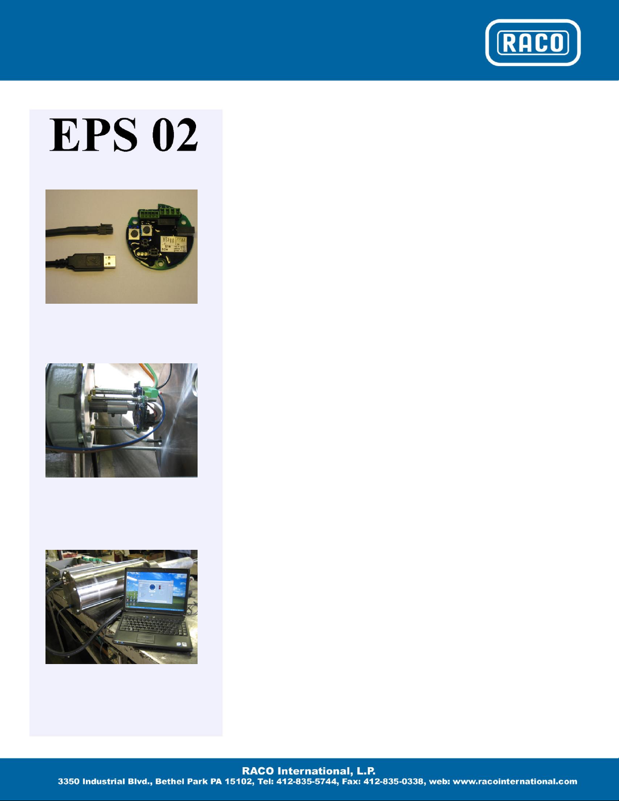
After installation of the RACO Tools
software, please check out the connectivity
between your laptop and the EPS02/EPS06
Electronic Position Sensor. Power up the
EPS02/EPS06 with a 24V DC power supply
and connect the TTL port (EPS02) / the USB
ports (EPS06) with an appropriate USB
cable. Start the RACO Tools application
program via the icon or the start program
menu.
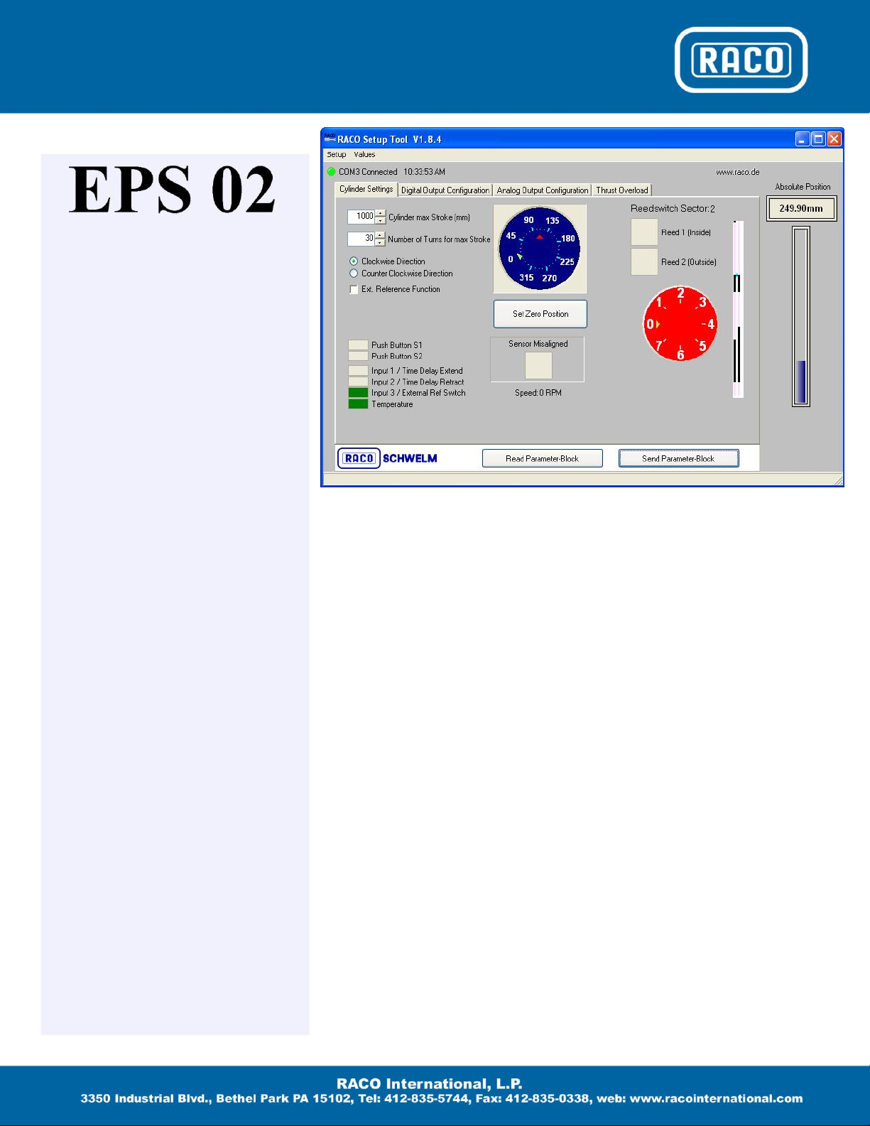
The connection is made successfully if the
LED symbol next to the text COM X
Connection in the upper left hand corner of
the main cylinder setting screen changes
fromred to green.
Connection Problem Trouble
Shooting
The most common problem is the
incorrect selection of the COM Port.
With the EPS02/EPS06 connected and
powered up please check under Control
Panel / System / Hardware / Device
Manager / Universal Serial Bus
Controllers that the communication
driver CP210x USB Composite Device
is loaded. Now click on Ports (COM &
LPT). The CP210x USB to UART
Bridge Controller should be loaded and
be pointing to the selected COM port
number. Use this COM port number in
conjunction with the RACO Tool
software. In the main RACO Tools
desktop window select the Setup pull
down command / Comport which will
open up a popup screen. Under Please
choose COM-Port select the assigned
COM port number and hit OK. The
LED symbol should change to green.
COM port numbers should be single
digit.
IF after the TTL / USB connection cable
is plugged into both the laptop and the
EPS02 / ESP06, and the CP210x USB
Composite Device is not loaded in the
device manager’s screen, the
communication driver has to be
installed manually. Please select the
subfolder USB and based on your
laptop’s operating system the
appropriate driver subfolder. Find the
file PreInstaller.exe and execute that
program. Follow the instructions of the
driver. Please make sure that you have
administrative rights.
There may be other vendor programs
installed on your laptop which may bind
the UART Controller to a driver
program during startup even if the main
program is not launched. These
programs are typically programs which
rely on a serial connection to talk to an
external device. One remedy is to de-
install that particular program or use a
different laptop.

Wiring Diagram
Examples
The EPS 02 limit switch contacts are hard
wired into the reversing motor starter circuit.
The EPS 02 output signals are wired as
permissive signals into the control circuit of
a variable frequencydrive.
Table of contents
Popular Accessories manuals by other brands

OYPLA SPORTS
OYPLA SPORTS 3350 user manual

CALECTRO
CALECTRO Uniguard Superflow UG3-A-SENSE Installation instruction

Bin Master
Bin Master NCR-80 operating instructions

La Crosse Technology
La Crosse Technology TX-63U-IT instruction manual

Allen-Bradley
Allen-Bradley Rockwell Automation VisiSight 42JT installation instructions

Shademaker
Shademaker Rope and Pole installation instructions

Chacon
Chacon DI-O quick guide

ekwb
ekwb EK-Momentum MSI Z390 MEG ACE installation manual

PCB Piezotronics
PCB Piezotronics IMI SENSORS M641B11 Installation and operating manual

Elements
Elements Thermotorch 5 94552 instructions

Half Price Blinds
Half Price Blinds Folding Arm Awning Fitting instructions

GEENI
GEENI SMART WI-FI DOOR SENSOR Start guide