RADEMACHER RolloSystems T2 User manual

GB Operating instructions for RolloSystems T2
VBD 509-1-GB (09.09)
Article No.: RS-T2-80

2
GB
i
...describe how to connect and operate the RolloSystems T2.....
Before you begin work, please read these instructions through completely and follow all the
safety instructions.
Please store these instructions in a safe place and pass them on to any future owners.
Damage resulting from non-compliance with these instructions and safety instructions will void
the guarantee. We assume no liability for any consequential damage.
Dear Customers, ...
... With your purchase of this drive for sliding doors and sliding shutters you have chosen
a quality product manufactured by Rademacher. We would like to thank you for your confidence.
The RolloSystems T2 has been developed with the greatest possible convenience in mind.
Having applied uncompromising quality standards, and carried out thorough testing, we are proud
to be able to present you with this innovative product.
It’s brought to you by all the highly-qualified personnel
here at RADEMACHER.
These instructions...
i
Key to symbolsi
Danger of fatal electric shock
This sign warns of danger when working on electrical connections, components, etc. It requires
that safety precautions be taken to protect the life and health of the person concerned.
This concerns your safety.
Please pay particular attention and carefully follow all instructions marked with this symbol.
NOTE/IMPORTANT/CAUTION
This is to draw your attention to information that is important for trouble-free operation.

3
GB
i
Introduction ................................................................................................................... 2
Key to symbols .............................................................................................................. 2
General view ................................................................................................................. 4
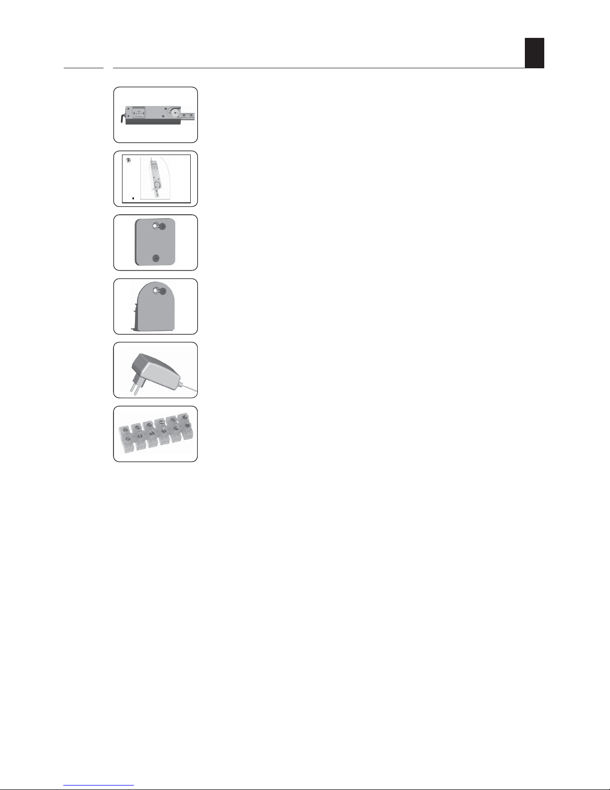
Included in delivery ........................................................................................................ 5
Correct usage ................................................................................................................ 6
Permissible sliding doors / sliding shutters ........................................................................ 6
Operating conditions ....................................................................................................... 6
Incorrect usage .............................................................................................................. 7
General safety instructions ............................................................................................... 8
Functional description .............................................................................. 9
- Obstacle detection ................................................................................................. 10
- Manual decoupling ................................................................................................ 10
Overview of features ........................................................................... 11
Important information prior to assembly and installation .................................................... 12
Electrical connection / Power supply ............................................................................... 13
+ 12 V output .................................................................................................... 13
Brief description of control inputs .................................................................................... 14
Connecting an external sensor or motion detector ............................................................. 15
Connecting a roller shutter switch ................................................................................... 16
Connecting the ArtMotion motion detector ....................................................................... 17
Drive menu structure ............................................................................ 19
Calling up functions / Setting assistance / Operation........................................................ 19
Calling up the menu and selecting a function (Example) .................................................... 20
Installation sequence............................................................................. 21
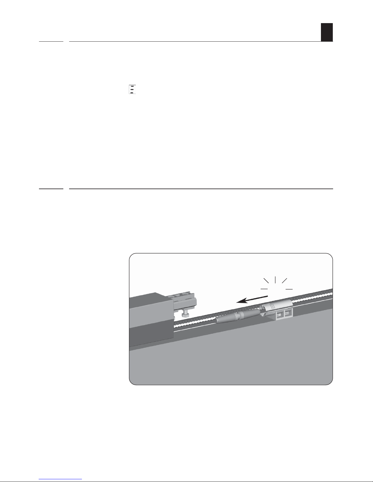
Automatic end point search / Brief explanation ................................................................ 22
Starting automatic end point search ................................................................................ 23
Reversing the running direction ...................................................................................... 24
Setting the braking distance .......................................................................................... 25
Setting the sensitivity of obstacle detection ...................................................................... 26
Setting speeds, automatically and manually ..................................................................... 27
1. Automatic setting of the speed according to the type of mounting .............................. 28
2. Switching to manual setting of opening speed ........................................................ 28
3. Switching to automatic speed setting according to the type of mounting ..................... 29
Setting the closing speed .............................................................................................. 30
Activating automatic closing ........................................................................................... 31
Switching acoustic signal on/off .................................................................................... 32
Switching Push mode on/off ......................................................................................... 33
Setting the function of control inputs Aand B................................................ 34
Clear / Deleting all settings / Viewing software version .................................................... 37
Activating/deactivating a radio motion detector ................................................................ 38
Activating/deactivating a manual transmitter ................................................................... 40
Obstacle detection / What to do if... ? ........................................................................... 42
Automatic synchronisation after power failure ................................................................... 43
Automatic synchronisation at the „Closed“ end point......................................................... 43
Error messages ............................................................................................................ 44
Technical data / RolloSystems T2 .......................................................... 45
- Factory settings .................................................................................................... 46
- Testing ................................................................................................................ 46
Warranty conditions ...................................................................................................... 47
Contents

4
GB
i
9
1
2
3
4
8
5
6
7
10
General view
Legend
1=Plus key
2=
OK
OK key
3=Minus key
4= Toothed belt wheel
5= Assembly block
6= Toothed belt wheel cover
7= Operating panel lid
8= LED display
9= Connecting cable
10 = Type plate

5
GB
GB Operating instructions for RolloSystems T2
VBD 509-1-GB (09.09)
ArticleNo.: RS-T2-80
i
1.
2.
3.
4.
5.
6.
After unpacking the product, compare the
contents of the package with this list:
1 x Drive
1 x Operating instructions
1 x Operating panel lid *
1 x Toothed belt wheel cover *
1 x 24 V mains power adapter
1 x Connecting terminal
* incl. screws
1.
2.
3.
4.
5.
6.
Included in delivery

6
GB
iCorrect usage
Use the RolloSystems T2 exclusively:
◆To open and close sliding doors and sliding shutters of the respective permissible maximum
weight, in private households.
◆According to the information and security requirements given in this manual.
Any other usage would be regarded as improper use.
◆Single-wing or double-wing sliding doors with a maximum weight of 80 kg.
◆The sliding door or sliding shutter fittings must correspond to DIN 1527 load class 6 (length
of useful life) and load class 3 (initial friction).
Permissible sliding doors / sliding shutters
i
Operating conditions
i
◆An easily accessible 230 V/50 Hz socket must be available at the installation site.
◆Only install the mains power adapter in dry rooms.
◆It should be possible to easily open and close the sliding door or sliding shutter by hand, the
door or shutter should not stick, and must be installed horizontally.
◆The sliding door or sliding shutter must be of a design with solid (fixed, immovable) end
stops.

7
GB
i
The RolloSystems T2 must not be used:
◆Without making the required adjustments for type of mounting/speeds (see page 27) and
end points (see page 22).
◆To operate doors that are subject to building inspectorate specifications:
- Fire doors
- Smoke control doors
- Escape doors
- Doors in escape routes etc.
Incorrect assembly may lead to risk of injury
The manufacturer is not liable for damages resulting from incorrect or improper use (see page
47).
Observe the instructions in the guide rail system assembly manual.
Incorrect usage

8
GB
iGeneral safety instructions
Work on electrical systems entails the risk of fatal electric shock.
◆Always remove the mains power adapter from the socket before carrying out any work on
the RolloSystems T2 or on the sliding door or sliding shutter.
The use of defective equipment can lead to personal injury and damage to
property.
◆Never use defective or damaged equipment.
◆Check that the drive and power unit are intact.
◆Please contact our Customer Service (see page 48) should you discover damage to the
system.
With power-driven sliding doors/sliding shutters there is a risk of injury through
crushing or cutting of a limb at the closing edges.
◆Please ensure that no one remains in the range of motion of the sliding door/sliding
shutter during operation.
Incorrect use leads to an increased risk of injury.
◆Never reach into moving sliding doors/sliding shutters or into actuated components.
◆Brief all parties involved in how to use the system safely.
◆Keep children away from travelling sliding doors/sliding shutters whenever these are in
movement.
◆Forbid children from playing with the sliding door or sliding shutter, or with the external
controls.
◆Keep remote controls somewhere that prevents them being used accidentally, e.g. by children
playing.
◆Only pass through sliding doors/sliding shutters when they are fully open and at a standstill.
If safety attachments are defective or out of operation there is a risk of injury
or damage to property.
◆Set the speed according to the type of mounting.
◆Keep the path of travel free of foreign bodies, (e.g. ice, snow, dirt and stones).

9
GB
iFunctional description
The RolloSystems T2 can be used to automate standard sliding doors/sliding shutters. The system
is assembled using the corresponding assembly set.
Simple menu navigation for rapid installation
Simple menu navigation enables the system to be installed rapidly and all major parameters to be
adjusted. With its wide range of setting options, the drive can be adapted to site-specific conditions
and individual requirements.
Installation is also made easier by automated sequences. For example, the end points are auto-
matically learned and saved.
Gentle motion sequences lessen wear and tear
The movement of the sliding door/sliding shutter is initiated with a soft start, and before the end
point is reached the drive switches to soft stop so that the movement ends slowly.
Safety functions
An obstacle detection function monitors the movement of the sliding door/sliding shutter for
malfunctions (see below). Additionally the drive can be manually decoupled should a malfunction
occur (e.g. in the event of power failure).
Power supply
The sliding door drive is operated by means of 24 V safety low voltage, so it is supplied with a
corresponding 24 V power unit which can be plugged into any 230 V / 50 Hz power socket.
Flexible connection options for additional operating units
The RolloSystems T2 has two control inputs and one 12 V output for connecting external sensors,
motion detectors, tread sensors and other pulse sensors.
Definition of terms
For simplicity, the term „sliding unit“ will be used in the following chapters instead of „sliding
door/sliding shutter“.

10
GB
iFunctional description / Obstacle detection
The drive features an automatic obstacle detection sensor.
If the sliding unit should encounter an obstacle when opening or closing, the drive stops automatically
and travels approx. 30 cm in the opposite direction.
Display as soon as an obstacle is identified.
NOTE
In certain circumstances, the obstacle detection sensor may incorrectly identify an obstacle, in
which case proceed as detailed on page 42.
Functional description / Manual decoupling
i
The RolloSystems T2 has a manual decoupling function.
In the event of a malfunction (e.g. power failure) the sliding unit can be decoupled from the drive
and moved by hand by giving it a hefty push. To recouple the sliding unit it has to be brought back
into position in relation to the toothed belt connector. When correctly positioned the follower will
clearly latch into the toothed belt connector.
Click

11
GB
iOverview of features
RolloSystems T2 functions and features
◆Automatically learns the end points
◆Automatic obstacle detection
◆Automatic synchronisation after power failure
◆Adjustable obstacle detection sensitivity
◆Adjustable speeds (for opening and closing)
◆Adjustable automatic closing
◆Integral receiver for manual transmitter (433 Mhz Keeloq and radio motion detector)
◆Adjustable Soft Start and Soft Stop
◆Power supply with 24 V safety low voltage
◆12 V output (e.g. as power supply for motion detector and sensor)
◆Adjustable inputs for connecting control units

12
GB
Important information prior to assembly and installation
Before assembly, check:
◆... whether your sliding unit is suitable for the drive and
◆... that the sliding unit/ the mechanism is in perfect mechanical working order. It should be
possible to open and close the sliding door or sliding shutter easily.
Check the weight of the sliding unit
◆The permissible total weight of 80 kg should not be exceeded, otherwise the drive may not
operate faultlessly. Therefore check the total weight of the sliding unit(s) before assembly
(e.g. with bathroom scales).

13
GB
Electrical connection / Power supply
The power is supplied via the 24 V mains power adapter provided.
NOTE
Note the information given on the 24 V mains power adapter’s type plate. It gives all the information
necessary for connecting the drive.
Assignment of the connecting
cable on the 24 V mains power
adapter
Assignment of the connecting
cable on the drive
The polarity of the power unit cable is shown by a marking:
Wire Polarity Drive cable
not marked = + 24 V green (5)
marked = GND (ground) brown (1)
+ 12 V output (power supply for motion detector and sensor)
The drive has a + 12 V output for connecting external sensors and motion detectors.
Colour assignment of the drive cable for the + 12 V output
Drive cable Assignment
pink (6) = + 12 V output (max. 70 mA)
grey (2) = GND (ground)

14
GB
Brief description of control inputs Aand B
Connection of external controls
The drive has two control inputs Aand Bfor connecting various external controls,
such as:
◆Sensor
◆Motion detector etc.
◆Roller shutter switch
Colour assignment of the drive cable for the control inputs
Drive cable Assignment
white (3) = control input A
yellow (4) = control input B
Setting the function of the control inputs (see page 34)
The function of each control input can be set as needed. This is done in menus and .
The following functions can be set:
◆Off
◆NC mode (potential-free opener contact)
◆NO mode (potential-free closer contact)
◆Pause mode (potential-free closer contact)
◆Opening, potential-free closer contact
(dead-man operation, e.g. for roller shutter switches)
◆Closing, potential-free opener contact
(dead-man operation, e.g. for roller shutter switches)
Permissible voltage for control inputs
Input voltage: 9 V to 24 V
Input resistance: > 47 kΩ
IMPORTANT
Control inputs not in use must be connected to GND, brown (1) or grey (2).

15
GB
Connecting a potential-free opener contact as per + 12 V (NC mode).
pink (6)
12 V
Control input
Potential-free
opener contact
Setting mode in menu or :
Switching signals: OPEN - STOP- CLOSE - STOP...
Switching signal if menu is enabled: OPEN (opening)
(Menu = Automatic closing)
NOTE
When connecting several motion detectors or sensors to this input, the switch contacts in this
mode must be switched in series.
Connecting a potential-free closer contact as per + 12 V (NO mode).
pink (6)
12 V
Control input
Potential-free
closer contact
Setting mode in menu oror
oror
or :
Switching signals: OPEN - STOP- CLOSE - STOP...
Switching signal if menu is enabled: OPEN (opening)
(Menu = Automatic closing)
NOTE
When connecting several motion detectors or sensors on this input, the switch contacts in this
mode must be switched in parallel.
Connecting an external sensor or motion detector

16
GB
Connecting a potential-free roller shutter switch with + 12 V.
pink (6)
12 V
Control input
Awhite (3)
Byellow (4)
Potential-free closer
contact of a roller shutter
switch
(example)
Setting mode in menu and : (when both inputs are in use)
Control input A (open)
Control input B (close)
Switching signals: OPEN (opening) or CLOSE (closing)
NOTE
◆Dead-man operation
The drive moves the door in the corresponding direction for as long as the signal persists. If
the signal lapses during travel the drive stops.
◆Control inputs Aand Bmust not both be set to mode and . If the required
application can be implemented using only one control input, the second control input can be
set to any other function.
Further applications:
◆Automatic operation with the aid of a thermostat.
For this function a thermostat must be connected via a changeover contact.
◆Automatic operation with the aid of a timer control (e.g. a 230 V roller
shutter control).
For this function the roller shutter control must be connected using a cut-off relay.
CAUTION
The cut-off relay must maintain the necessary safety barrier between the 230 V mains and
the low-voltage side.
Connecting a roller shutter switch

17
GB
Connecting the ArtMotion motion detector
Connecting the motion detector in closer mode (NO)
The radar motion detector ArtMotion is recommended for use with the RolloSystems T2. It must
be operated in „High Active“ mode – refer to the motion detector assembly and operating
instructions.
Settingof the respective control inputs:
Connecting two ArtMotion motion detectors in closer mode
+ 24 V
GND
+
ArtMotion
Power
Supply
Potential-
free
output
white white
brown
brown
green
green
yellowyellow
Cable
green (5)
brown (1)
grey (2)
white (3)
or
yellow (4)
Control-
input
RolloSytems T2
ArtMotion 1 ArtMotion 2
RolloSystems T2
yellow
green
brown
white
yellow
green
brown
white
green
brown/grey
yellow
white Control input
+ 24 V
GND (ground)
If an input is already assigned for a sensor or other device, the motion detector can be
connected to an input in parallel (see page 18).

18
GB
Connecting the ArtMotion motion detector
Parallel connection of two ArtMotion motion detectors in closer mode
ArtMotion 1 ArtMotion 2
RolloSystems T2
green
brown/grey
yellow
or
white
+ 24 V
GND (ground)
Control input
amarillo
verde
marrón
blanco
amarillo
verde
marrón
blanco

19
GB
Plus key
OK OK key
Minus key
LED display
Calling up functions / Setting assistance / Operation
The drive has three operating keys and an LED display. All functions can be accessed and the
required settings made using the operating keys. The LED display provides information on the
function selected and the status of the function.
Drive menu structure
All necessary settings can be made in the drive control menu. Functions are selected via the
menu. The following table gives a brief introduction to the individual functions:
/
End point search
Reverse running direction
Set braking distance
Set sensitivity
Set mounting mode / opening speed
Set closing speed
Set automatic closing
Acoustic signal
Push mode
Set function of control inputs A and B
Clear (restore factory settings)
Activate radio motion detector
Activate/deactivate manual transmitter

20
GB
Calling up the menu and selecting a function (Example)
Display after plugging the power unit
into a 230 V socket.
The drive is idle (in standby mode).
1.
OK Press for two
seconds
Select a function.
e.g. „Function of control input A“
3. /
4.
5. /
Keys LED display
Call up the menu.
Confirm the selection and switch to
setting mode.
The display flashes.
Set the required function.
e.g. (closer contact, NC)
Return to menu.
Exit the menu.
The drive then returns to idle.
NOTE
If no key is pressed for 30 seconds, the drive auto-
matically returns to idle mode.
Changes to settings are nevertheless saved.
6.
7.
2.
Press for two
seconds
OK
OK
OK
Table of contents
Other RADEMACHER Door Opening System manuals
Popular Door Opening System manuals by other brands

Erreka
Erreka VIVO-M101 Quick installation and programming guide

DORIC
DORIC DS3006 installation guide

Micom
Micom EDM MM50 installation instructions

Dormakaba
Dormakaba ED900 installation instructions

Assa Abloy
Assa Abloy Norton 78-B/FHA Hold Open Series installation instructions

Open Sesame Door Systems
Open Sesame Door Systems 133 installation guide