RADEMACHER Troll Standard 5620 User manual

VBD 592-2 (01.21)
Item no. 3650 03 12 (ultra white) / 3650 03 22 (aluminium)
EN
Troll Standard
Instruction manual for the electrical connection and for commissioning
Type: 5620

2
EN
i
Contents
1. This manual..........................................................................................4
1.1 How to use this manual....................................................................4
2. Hazard symbols...................................................................................5
2.1 Levels of danger and signal words................................................5
2.2 Symbols and depictions used.........................................................6
3. Safety instructions..............................................................................7
3.1 Intended use.........................................................................................8
3.2 Improper use ........................................................................................8
3.3 Expert knowledge required by the installer..............................8
4. Included in delivery............................................................................9
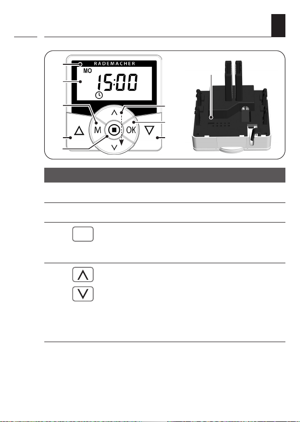
5. General view of the operating unit................................................10
5.1 General view of the installation housing................................. 12
5.2 Electrical connections .................................................................... 13
5.3 Display and its symbols ................................................................. 14
6. Product description..........................................................................15
6.1 Description of the safety functions ........................................... 16
6.2 Overview of functions.................................................................... 16
7. Technical specifications ...................................................................18
7.1 Werkseinstellungen......................................................................... 20
7.2 Conduct in the event of a power failure .................................. 21
8. Safety instructions for the electrical connection ........................22
8.1 Important information prior to the electrical
connection and installation ......................................................... 24
8.2 Electrical connection ...................................................................... 25
9. Installation after the electrical connection ..................................27
10. Brief description of the standard display and main menu........28
11. Introduction to opening the menus and
setting the functions ........................................................................29
12. Initial commissioning with the help of the
installation wizard ............................................................................31

3
EN
Contents
i
13. Manual operation .............................................................................33
14. Memory function - accepting the current time
as switching time ..............................................................................34
15. Menu overview..................................................................................35
16. Menu 1 - Switching automatic mode on/off ................................36
17. Switching times (opening and closing times) [ / ],
brief description................................................................................37
17.1 Menu 2 - Configuring opening and closing times [ / ] .. 38
18. Menu 6 - Configuring the random function.................................40
19. Menu 9 - System settings.................................................................41
19.1 Menu 9.1 - Setting the time and date....................................... 42
19.2 Menu 9.5 - Configuring the switching time programme... 43
19.3 Menu 9.6 - Configuring the blockage detection................... 44
20. Menu 9.8 - Device settings ..............................................................47
20.1 Menu 9.8.1 - Switching the automatic summer/winter
time on/off ......................................................................................... 48
20.2 Menu 9.8.2 - Setting the display contrast................................ 49
20.3 Menu 9.8.4 - Setting the timer mode........................................ 49
20.4 Menu 9.8.5 - Switching the button lock on / off.................... 50
20.5 Menu 9.8.7- Switching the reversal of rotation
direction on/off................................................................................. 51
20.6 Menu 9.8.0 - Displaying the software version........................ 52
21. Deleting all settings, software reset..............................................53
22. Performing a hardware reset..........................................................54
23. Error messages ..................................................................................55
24. Dismantling........................................................................................55
25. Simplified EU declaration of conformity.......................................56
26. Warranty terms and conditions......................................................57

4
EN
i
1. This manual...
...describes how to install, connect the electrical system and operate
the Troll Standard.
1.1 How to use this manual
◆Before you begin, please read this manual through completely and
follow all the safety instructions.
◆Please also read the instruction manuals for the accessories (if avail-
able) as well as the manuals for the respective connected electrical
appliances.
◆This manual is part of the product. Please store it in an easily acces-
sible place.
◆When passing the Troll Standard on to a third party, this manual
must be passed on as well.
◆Damage resulting from non-compliance with this manual
and the safety instructions will void the warranty. We assume
no liability for any resulting damage.
i

5
EN
i
2. Hazard symbols
The following hazard symbols are used in this manual:
Danger of fatal electric shock
Danger area / dangerous situation
2.1 Levels of danger and signal words
DANGER!
This hazard will lead to serious injury or death if not avoided.
WARNING!WARNING!
This hazard may result in serious injury or death if not avoided.
CAUTION!
This hazard may result in minor or moderate injury if not avoided.
ATTENTION!
This hazard may lead to property damage.
i

7
EN
3. Safety instructions
There is a risk of fatal electric shock when touching electrical
components.
◆The electrical connection and all work on electrical systems must
only be carried out by a qualified electrician in accordance with the
connection instructions in these operating instructions.
◆All connection and installation work must only be carried out in a
de-energised state.
The use of defective devices can lead to personal injury and
damage to property (electric shocks / short circuiting).
◆Never use defective or damaged devices.
◆Check the Troll Standard for damage.
◆Please contact our Customer Service if you find any damage, see
page 60.
Improper use leads to an increased risk of injury.
◆Train all personnel to use the Troll Standard safely.
◆This device may be used by children from 8 years of age upwards as
well as by persons with reduced physical, sensory or mental capaci-
ties or with lack of experience and knowledge if they are supervised
or have been instructed on how to use the device safely and if they
understand what dangers may resulted from this.
◆Children must not play with the device.
◆Never remove the operating unit from the installation housing
during operation.
i

8
EN
3.1 Intended use
Use the Troll Standard only for connecting and controlling a tubular
motor for roller shutters, Venetian blinds, slats or awnings.
Operating conditions
◆The tubular motor must be fitted with a mechanical or electronic
end position switch.
◆Only operate the Troll Standard in dry rooms.
◆A 230 V/50 Hz power supply, together with a site-provided discon-
necting device (fuse), must be available at the installation location.
3.2 Improper use
Using the Troll Standard for purposes other than those previously men-
tioned is impermissible.
There is a risk to life caused through short circuiting and electric
shocks if the Troll Standard is used outside or in damp rooms.
Do not install and use the Troll Standard outdoors or in damp rooms.
3.3 Expert knowledge required by the installer
The electrical connection, installation and commissioning of the Troll
Standard must only be carried out by a qualified electrician in accord-
ance with the instructions in this manual..
i
i
i

9
EN
i
4. Included in delivery
Included in delivery
a) 1 x Operating unit (50 x 50 mm)
b) 1 x Frame
c) 1 x Installation housing
d) 1 x Instruction manual (not illustrated)
After unpacking please check and compare ...
... the contents of the package with those specified above.
a)
b) c)

10
EN
i
5. General view of the operating unit
1)
Pos. Symbol Description
1) Operating unit
2) Display
3)
M
Menu button
◆Open the main menu
◆Back to the previous menu or standard display
4) Setting buttons
◆Select a menu in the main menu
◆Set the parameters (more / less)
●Short press or press and hold =
gradual or quick setting
◆Switch functions on / off (On / OFF)
3) 4)
5)
6)
7)
8)
9)
2)

11
EN
Pos. Symbol Description
5)
OK
OK button
◆Open the selected menu
◆Confirm and save settings
◆Continue to the next setting
6) Operating buttons Up / Down
◆Manual operation
7)
8) SET/Stop button
◆Manual stop of the roller shutter travel
◆Set (adjust) various functions
9) Bridging contact for a hardware reset
◆See page 54
5. General view of the operating unit
i

12
EN
5.1 General view of the installation housing
10)
11)
Pos. Symbol Description
10) Installation housing
11) Claw fasteners and screws
12) Connecting terminals
13) Type plate
i
13)
12)

13
EN
14)
Pos. Symbol Description
14) E1 / E2 External inputs - optional
Connect external signal transmitters or external
controllers (e.g. Troll Comfort), see page 26.
15) L / N Power supply - 230 V / 50 Hz
Connect the supply voltage.
16) / Rotation direction (up / down)
Connecting cables to the tubular motor.
5.2 Electrical connections
15)
i
16)

14
EN
i
Symbol Description
MO ... SO Weekdays (Monday ... Sunday)
Time / setting parameters
Information
Switching time programme
SET Setting
AUTO Automatic mode
IST Ist-Wert
Direction of travel (up/down)
Automatic mode off
Switching times
Random function
System settings
Blockage detection
Automatic button lock
5.3 Display and its symbols

15
EN
i
6. Product description
The Troll Standard controller is designed for controlling roller shut-
ters, Venetian blinds, slats or awnings by connecting a corresponding
tubular motor.
Roller shutter control
The device enables the roller shutter to be automated.
Manual operation
It is possible to manually control the connected tubular motor at any
time by using the controls.
External control via two inputs E1 and E2
The Troll Standard features two inputs E1 and E2 (230 V / 50 Hz) for
connecting external signal transmitters or external controllers (e. g. Troll
Comfort), see page 26.
Installation and electrical connection
The Troll Standard is designed as a flush-mounted device for indoor
rooms. The electrical connection is carried out by means of the
connecting terminals on the reverse side of the installation housing.
Installation / compatible switch ranges
The Troll Standard can be integrated into standard switch ranges
(50 x 50 mm).
i
It may be necessaryto use an intermediateframe *50x 50 (accor-
ding to DIN 49075) depending on the switch range used.
* Not included

16
EN
i
6.1 Description of the safety functions
Blockage detection
The Troll Standard is able to monitor the torque of motors equipped with
a mechanical end point setting. This enables the controller to switch off
the motor in the event of overloading or blockage, see page 44.
6.2 Overview of functions
◆Installation wizard for easy commissioning
◆Configurable blockage detection for mechanical tubular motors
◆Manual operation on site
◆Switch automatic mode on/off
◆Easy configuration with menu-driven operation
◆Switching times
●Configurable opening []and closing times []for your roller
shutter
◆Switching time programme:
●Weekly switching times
−One switching time pair [/ ]for [ MO...SO ] (MON...SUN)
●Weekday and weekend switching times
−One switching time pair [/ ]for [MO...FR ] (MON...FRI)
−One switching time pair [/ ]for [SA + SO ](SAT + SUN)
◆Random function (random delay of 0 to 30 minutes)
◆Button lock
i

17
EN
i
6.2 Overview of functions
◆Memory function (easy acceptance of the current time as switching
time)
◆Switch reversal of rotation direction on/off
◆Automatic summer / winter changeover
◆Permanent storage of the settings
◆External control via the two inputs E1 / E2
◆Delete or reset all data
Description and configuration of the individual functions
A precise description of the individual functions and settings is includ-
ed starting on page 28.

18
EN
i
7. Technical specifications
Mains supply [ L / N ]
Mains supply
voltage: 230 V / 50 Hz
Consumption: Standby: < 0.6 W
2 x extension inputs [ E1 / E2 ]
onnection of external signal transducers/eternal controllers
Input voltage: 230 V / 50 Hz (Ri = 200 kW)
Maximum cable length: 15 metres
Rotation direction [ s/ t ]
Switching voltage: 230 V / 50 Hz
Maximum switching capacity: M8 (4) A µ (Type 1B)
Improper use can lead to serious injuries or property damage.
◆Due to the small contact distance (µ), not suitable for disconnecting.
◆The Troll Standard is not suitable to be used for an electrically safe
disconnection of the connected appliance

19
EN
i
7. Technical specifications
General information
External dimensions (W x H x D)
Operating unit [1 ]:
50 x 50 x 12 mm
according to DIN 49075
Available colours: Ultra-white (UW),
Aluminium (AL)
Installation depth: 32 mm
Permissible ambient
temperature range: 0 °C to + 40 °C
Protection class: II (only for use in dry rooms)
Connecting terminals: Screw terminals for max.
1.5 mm2 cable cross-section
Power reserve for the timer in
the event of a power failure approx. 8 hours

20
EN
i
7.1 Werkseinstellungen
Factory settings
Automatic mode: On
Switching times: On
Date: 01.07.2018
Time: 12:00
Up-time and mode: 7:00
Down-time and mode: 20:00
Random function: OFF
Switching time programme: 1
Blockage detection: OFF
- Motor type: 2 (45 mm / 30 Nm)
- Sensitivity: 230
- Reversing function: OFF
Automatic summer / winter
changeover: On
Display contrast: 8
Timer mode: 1 (50 Hz)
Button lock: OFF
Reversal of direction of rotation: OFF
This manual suits for next models
2
Table of contents
Other RADEMACHER Timer manuals

RADEMACHER
RADEMACHER SpeedTimer 3650 05 12 Specification sheet

RADEMACHER
RADEMACHER 3650 05 12 User manual

RADEMACHER
RADEMACHER Modi 2650 Quick guide

RADEMACHER
RADEMACHER Troll Comfort DuoFern User manual

RADEMACHER
RADEMACHER Troll Basic DuoFern 5615 User manual

RADEMACHER
RADEMACHER DuoFern HomeTimer 9498-UW User manual