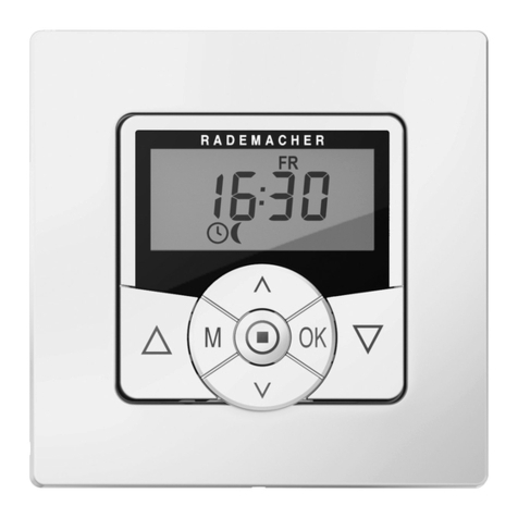
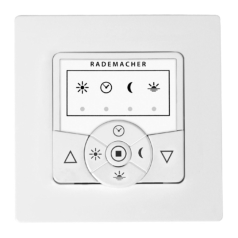
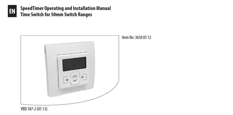
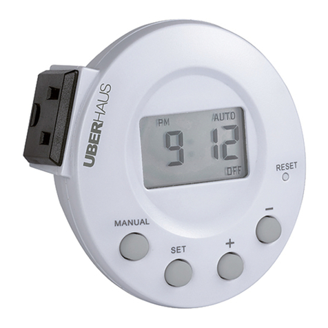
RADEMACHER 3650 05 12 User manual

VBD 587-2 (12.21)
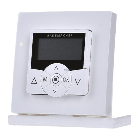
SpeedTimer
Translation of Operating and Assembly Manual for 50 mm Switch Ranges
Item no. 3650 05 12
EN

2
i
1. This manual ........................................................3
2. Included in delivery ............................................4
3. Overall view - controls and installation housing...5
4. Display symbols ..................................................6
5. Hazard symbols ...................................................7
6. Safety instructions...............................................8
7. Intended use .......................................................9
8. Improper use .....................................................10
9. Functional description.......................................10
9.1 Overview of functions..............................12
10. Important information prior to the electrical
connection and installation ...............................13
11. Safety instructions for the electrical connection 15
12. Electrical connection of the SpeedTimer ............16
13. Installation........................................................17
14. Important information prior to configuration....18
14.1 Brief description of the standard display
and main menu .......................................19
14.2 Introduction to opening and closing
the menus ...............................................20
15. Initial commissioning with the help of the
installation wizard.............................................21
16. [AUTO] automatic mode and [ ] manual
mode ................................................................23
16.1 Menu 1 - Switching between [AUTO] auto-
matic mode and [ ] manual mode........24
17. Opening and closing times [ ]........................25
17.1 Menu 2 - Configuring opening and
closing times [ ]...................................27
18. Automatic dusk function....................................29
18.1 Menu 3 - Customising the automatic
dusk function [ ]. .................................31
19. Automatic sun function .....................................33
19.1 Menu 4 - Configuring the automatic
sun function [ ]....................................35
20. Random function [ ]......................................36
20.1 Menu 5 - Configuring the random
function [ ]..........................................37
21. Menu 6 - System settings [ ] .........................38
21.1 Menu 6.1 - Setting the time and
date [ ].................................................39
21.2 Menu 6.2 - Entering the postcode [PLZ]...40
21.3 Menu 6.3 - Activating/deactivating the
week programme [ ]............................41
21.4 Menu 6.4 - Configuring the blockage
detection [ ].........................................42
21.5 Menu 6.5 - Activating/deactivating the
automatic summer/winter changeover....46
21.6 Menu 6.6 - Configuring the total running
time and Venetian blind mode [ T ]..........48
21.7 Menu 6.7 - Displaying software version ...51
22. Software reset (restore the default factory
settings)............................................................52
23. Performing a hardware reset .............................53
24. Dismantling.......................................................54
25. Simplified EU declaration of conformity.............55
26. Technical specifications......................................56
27. Factory settings.................................................57
28. Time zone table.................................................58
29. Menu overview..................................................60
EN
Table of Contents
3
iEN
...describeshowtoinstall,connect and operatetheSpeedTimer.
Before you begin, please read this manual through
completely and follow all the safety instructions.
This manual is part of the product. Please store it in an easily
accessible place. When passing the SpeedTimer on to a third
party, this manual must be passed on as well.
Damage resulting from non-compliance with this manual
and the safety instructions will void the warranty. We assume
no liability for any resulting damage.
1. This manual ...

4
iEN
2. Included in delivery
1.
2.
3.
Legend
1. Operating unit (50 x 50) mm
2. Frame
3. Installation housing
4. Light sensor (optional); item no. 7000 00 88 *
5. 2 x assembly screws (not illustrated)
6. 1 x operating manual (not illustrated)
* Not included
4. (optional) After unpacking, please check and compare...
the contents of the package with the above specified.
Check the details on the type plate
Checkthatthevoltage/ frequency onthetype platecorresponds
to the local mains conditions.

5
iEN
3. Overall view - controls and installation housing
8. Up button
11. Connection socket
for the light sensor.
7. Display
10. Down button
13. Installation housing
9.
M
Menu button
12.
OK
OK button
14. Connecting terminals

6
iEN
4. Display symbols
MO (MON)... SO (SUN) - weekdays
8- time / setting parameters
Blockage detection
Week programme
AUTO - automatic mode
ACTUAL value
Direction of travel - up / down
Manual mode
Switching times
Dusk function Sun function
not assigned
Random function
Settings
T- jog mode
Automatic slat adjustment
NORMAL/ASTRO/SENSOR -
switching time modes
PLZ - postcode
OFFSET (for astro time)
SET value
L- not assigned

7
iEN
5. Hazard symbols
Risk of fatal electric shock.
This symbol warns of danger when working on electrical con-
nections, components, etc. It requires that safety precautions
be taken to protect the life and health of the person concerned.
Symbols and depictions used
This concerns your safety.
Please pay attention and follow all instructions marked with
this symbol.
i
Further useful
information
Pleasereadthe operatingmanualoftheexternaldevicedescribed
at this point (e.g. a tubular motor).

8
iEN
6. Safety instructions
There is a risk of fatal injury from electric shock when
working on all electrical systems.
◆The electrical connection and all work on electrical systems
must only be carried out by a qualified electrician in ac-
cordance with the connection instructions in this manual,
see page 16.
◆Carry out all installation and connection work
only in a de-energised state.
The use of defective devices can lead to personal injury
anddamagetoproperty (electricshocks,short circuiting).
◆Check the SpeedTimer for damage prior to installation.
◆Neverusedefective or damaged devices.Pleasecontact our
Service department in this case,.
Incorrect use leads to an increased risk of
injury.
◆Train all personnel to use the SpeedTimer safely.
◆Avoid allowing persons with limited abilities to operate
the device and prevent children from playing with the
SpeedTimer.
◆Neverremovetheoperatingunitfromtheinstallationhousing
during operation.

9
iEN
Only use the SpeedTimer for connecting and controlling a
tubular motor for:
◆Roller shutters
◆Venetian blinds and slats.
7. Intended use
Only use the manufacturer's original spare parts.
◆By doing so, you avoid the risk of malfunctions and damage
to the device or the connected tubular motor.
◆As the manufacturer, we provide no warranty for the use of
third-party components and accept no liability for conse-
quential damage resulting from such.
◆All repairs to the SpeedTimer must be undertaken by
authorised customer service personnel.
Operating conditions:
◆The tubular motor must be fitted with a mechanical or
electronic end position switch.
◆Only install and use the SpeedTimer in dry areas.
◆A230V/ 50 Hz powersupply, together with a site-provided
disconnecting device (fuse), must be available at the
installation location.

10
i
i
EN
9. Functional description
TheSpeedTimer is designed for controllingrollershutters/Vene-
tianblindsor slats by connectingacorrespondingtubularmotor.
Roller shutter control
Various modes make it possible to automate the roller shutters
according to time / sun / dusk or with a random controller.
8. Improper use
Using the SpeedTimer for purposes other than previously men-
tioned is impermissible. There is a risk of fatal injury caused through short circuit-
ing and electric shocks if the SpeedTimer is used outside.
◆Do not install and use the SpeedTimer outside.
Venetian blinds / slat control
Convenient control of Venetian blinds or slats with integrated
automatic slat adjustment.
Manual mode
It is possible to manually control the connected tubular motor at
any time by using the control buttons.

11
iEN
Installation
You can integrate the SpeedTimer into most commercially
available switch and frame ranges.
Compatible switch ranges
Manufacturer Switch range
BERKER Arsys / K1 / S1
BUSCH-JAEGER Busch-Duro2000Si/ReflexSi/ alpha
exclusive / alpha nea / solo / impuls
GIRA Standard system / S-Color
system / Stainless steel range /
Standard 55
JUNG CD 500 / ST 550 / LS 990 / CDplus
as per CD but with coloured rings
MERTEN M1 / Atelier / Artec /Trancent /
Antique New
PEHA Standard / Dialog / Aura
LEGRAND Creo /Tenara
VEDDER Alessa (plus)
i
The highlighted switch ranges are suitable for use with the
light sensor.
9. Functional description

12
iEN
9.1 Overview of functions
◆Installation wizard for easy commissioning.
◆Configurable blockage detection for mechanical
tubular motors. *
◆Manual control on site using generously-sized
UP/DOWN buttons.
◆Easy configuration with menu-driven operation.
◆Automatic timer
- Opening and closing time (up/down) valid for
every day of the week.
◆Week programme including:
- Individual daily programme, individual opening and
closing times (up/down) for every day of the week.
◆Astro dusk function with a
cut-off time (“latest at xx:xx hours”).
◆Automatic dusk function (via a light sensor) with a
cut-off time (“latest at xx:xx hours”).
◆Automatic sun function (via a light sensor)
◆Random function (random delay of 0 to 30 minutes).
◆Easy AUTO / MANUAL switchover.
◆Jog mode, configurable tilting time (reversing) forVenetian
blinds.
◆Configurable motor control time.
◆Automatic summer/winter changeover.
* Blockage detection can only be used in combination with a
mechanical tubular motor.
Description and configuration of the individual functions
A precise description of the individual functions and settings is
included starting on page 18

13
i
13.
14.
EN
The installation and elec-
trical connectionmayonly
be undertaken using the
enclosed installation hou-
sing (13).
The connecting terminals
(14) are located on the
bottom of the installation
housing.
10. Important information prior to the electrical connection and installation
You must configure the end stops of the tubular motor
prior to installationand before making the finalelectrical
connection.
◆If no end stops are configured, then it is vital that both end
points of the tubular motor are configured, as failure to do
so can lead to malfunctions.
◆In order to do so, follow the information provided in the
operating manual for the respective tubular motor.

14
EN
Parallel connection of electronic tubular motors
You can connect a maximum of 2 electronic tubular motors in
parallel to the SpeedTimer.
To do so, please refer to the operating manual for the respective
tubular motor.
i10. Important information prior to the electrical connection and installation
Parallel connection of mechanical tubular motors
Acut-offrelayis requiredin order to connectmechanical tubular
motors in parallel.

15
iEN
11. Safety instructions for the electrical connection
There is a risk of fatal injury from electric shock when
working on all electrical systems.
◆The electrical connection and all work on electrical systems
mustonly be carried outbya qualified electrician in accord-
ance with the connection instructions in this manual.
◆Carry out all installation and connection work only in a
de-energised state.
◆Disconnect all phases of the mains power lead and secure it
to prevent any reconnection.
◆Check that the system is de-energised.
◆Priortoconnecting,comparetheinformationaboutvoltage
/frequencyonthedevicewiththatofthelocalelectrical grid
operator.
Incorrect wiring may lead to short circuits and destroy
the device.
◆Follow the pin assignment detailed in the connection
diagram.
◆Follow all the electrical connection specifications in the
operating manuals of your tubular motor.

16
PE
N
L1
PE
N
▲
▲
▲
▲
▲
▲
▲
▲
MOTOR
1
N
N
N
L1
iEN
12. Electrical connection of the SpeedTimer

17
i
1.
2.
3.
EN
13. Installation
TheSpeedTimerisintendedfor flush-mounting.Werecommend
using a deep box.
You will need:
1 x 58 mm flush-mounted box
Installation procedure:
1. Switch off the mains.
2. Make the electrical connection according to the wiring diagram
(see page 16).
3. Route the power cables to the flush-mounted box.
4. Slide the installation housing (3) into the flush-mounted box
and screw in place with the screws.
5. Fit the frame (2).
6. Carefully insert the operating unit (1) into the installation
housing (3).
7. Switch the mains power back on again.
Mounting the light sensor, see page 33

18
iEN
14. Important information prior to configuration
All of the settings are menu-driven. In other words, you will be
promptedto carry out therequiredsettingsin a logical sequence
as shown on the display.
The operating system
◆TheSpeedTimer is operatedbymeansofthefourbuttonson
the control module. The individual menu items are shown
on the display.
◆Each entry must be confirmed with [OK].
The button functions:
Menu button, [M] button
◆Open the main menu.
◆Back to previous menu or standard display.
Up / Down buttons
◆Manual mode (Up / Down).
◆Select the desired menu item.
◆Settingtheparameters(pressingandholdingabuttonforan
extended period causes the digits to change more quickly).
M
OK
[OK] button
◆Confirms the selected menu.
◆Confirm and save entry.
◆Continue to next entry.

19
iEN
14.1 Brief description of the standard display and main menu
The standard display (example) Main menu
◆Displays the current date and time.
◆Displays the set mode and active functions.
◆Manual operation of the SpeedTimer is only possible
from the standard display.
◆Enables display and selection of the menu items and
individual functions.
◆Manual operation is not possible in this view.
◆If no button is pressed within 120 seconds, the display
changes back to the standard display. If this happens,
any settings that have not been confirmed with [OK] will
be lost.

20
i
▲
EN
1. Pressing the [M] button
in the standard display
causes the main menu
to open.
14.2 Introduction to opening and closing the menus
3. The selected menu is
opened by pressing the
[OK] button.
OK
M
Theselectedmenuisindicatedby
a number and a flashing symbol.
4. Press for 1 second.
Pressing the [M] but-
ton from any menu
will return you to the
standard display.
Briefly pressing the [M]
button causes the dis-
playto go back one menu
step.
If no button is pressed
within 120 seconds, the
display changes back to
the standard display.
M
approx.
1 s
approx.
120 s
2. The desired menu can
thenbeselectedbyusing
the[Up/Down] buttons.
Table of contents
Other RADEMACHER Timer manuals

RADEMACHER
RADEMACHER Troll Comfort DuoFern User manual

RADEMACHER
RADEMACHER Modi 2650 Quick guide

RADEMACHER
RADEMACHER Troll Basic DuoFern 5615 User manual

RADEMACHER
RADEMACHER Troll Standard 5620 User manual

RADEMACHER
RADEMACHER DuoFern HomeTimer 9498-UW User manual

RADEMACHER
RADEMACHER SpeedTimer 3650 05 12 Specification sheet