Radiancy Mistral User manual

User Manual
August 2009, Revision 07


User Manual
August 2009, Revision 07

ii
© 2007-2009 Radiancy Inc. All right reserved.
Mistral User Manual, August 2009. Part Number: 2011580. Revision 07
Note: The information in this document is confidential and proprietary. It is provided to
customers and authorized representatives of Radiancy only. The content of this manual is
furnished for informational use only, is subject to change without notice and should not be
construed as a commitment by Radiancy Inc.
LHE is a registered trademark of Radiancy Inc. in the United States and/or in other countries.
The Quality Management System of Radiancy Ltd. complies with the Quality Management
Standard ISO 13485-2003.
Manufacturer: Radiancy (Israel) Ltd., 5 Hanagar St., P.O. Box 7329, Hod
Hasharon, 45240, Israel, Tel: 972-9-775-7500, Fax: 972-9-775-7511
www.radiancy.com
Authorized European Representative: Obelis S.A,, Av. de Tervuren
34 Bte .44, B-1040 Brussels, Belgium. Tel: 32 (0) 2 732 5954, Fax: 32
KEMA Notified Body.
Contact Information
Customer satisfaction is a Radiancy priority. To help us in providing you with
the best possible product and support, please send us your comments and
suggestions. Contact us at the addresses and telephone numbers below:
US
Radiancy Inc.
40 Ramland Road South, Suite 200
Orangeburg, NY 10962
USA
Toll Free: 888 661-2220
Tel: +1 845 398-1647
Fax: +1 845 398-1648
com.diancyra@info:mail-E
Israel
Radiancy (Israel) Ltd.
5 Hanagar St., P.O. Box 7329
Hod Hasharon, 45240
Israel
Tel: +972-9-775-7500
Fax: +972-9-775-7511
E-mail: service@radiancy.com

iii
Table of Contents
1. INTRODUCTION TO THE SYSTEM 1
2. SYSTEM DESCRIPTION 2
2.1. S
YSTEM
C
OMPONENTS AND
C
ONTROLS
:........................................2
2.2. M
AJOR
P
RECAUTIONS
&
W
ARNINGS
..............................................7
3. INITIAL SET UP 14
3.1. U
NPACKING
M
ISTRAL
....................................................................14
3.2. E
LECTRICAL
R
EQUIREMENTS
........................................................14
3.3. I
NSTALLATION
..............................................................................15
4. OPERATION AND TREATMENT PROTOCOLS 17
4.1. G
ENERAL
G
UIDELINES FOR THE
O
PERATION OF
M
ISTRAL
................17
4.2. U
SING THE
T
OUCH
S
CREEN
C
OMPUTER
.........................................19
4.3. P
RE
-T
REATMENT
C
ONSIDERATIONS
..............................................35
4.4. P
RE
-T
REATMENT
P
REPARATIONS
..................................................36
4.5.
S
KIN
P
HOTO
R
EJUVENATION
........................................................40
4.6. H
AIR
R
EMOVAL
............................................................................47
4.7. A
CNE
T
REATMENT
........................................................................55
4.8. P
SORIASIS
T
REATMENT
................................................................60
4.9. S
KIN
T
IGHTENING
.........................................................................66
5. MAINTENANCE 71
5.1. C
LEANING
I
NSTRUCTIONS
.............................................................71
5.2. P
ARTS
&
A
TTACHMENTS
...............................................................73
6. ADVERSE EVENTS REPORT FORM 75
7. TROUBLESHOOTING 78
8. MISTRAL SERVICE 79
9. WARRANTY 80

iv
List of Figures
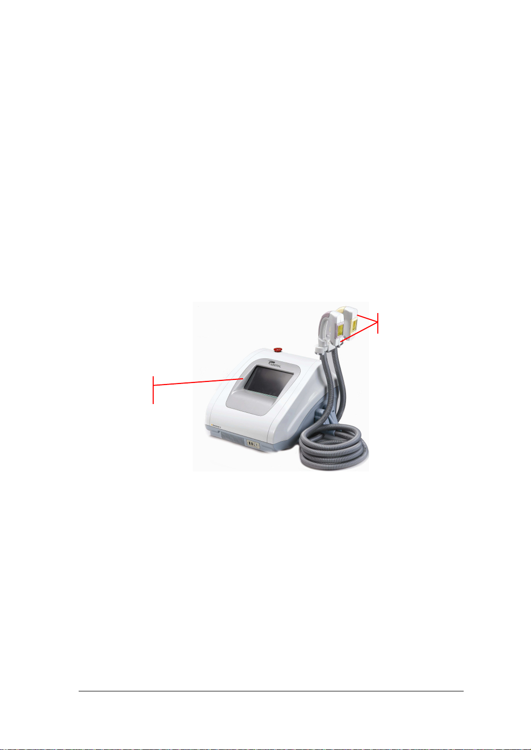
Figure 1: Mistral Main System......................................................................2
Figure 2: Front Panel ...................................................................................3
Figure 3: Back Panel....................................................................................3
Figure 4: Right Side Panel ...........................................................................4
Figure 5: Handpiece.....................................................................................4
Table 1: Handpiece Color Identification........................................................5
Figure 6: Footswitch.....................................................................................5
Table 2: Technical Specifications.................................................................6
Table 3: International Standards Labels.......................................................9
Table 4: Additional Labels...........................................................11
Figure 7: Handpiece Connection................................................................16
Figure 8 - Pulse Counters ..........................................................................19
Figure 9: Password Entry...........................................................................20
Figure 10: Home Page...............................................................................21
Figure 11: Tutorial/Help Page ....................................................................21
Figure 12: Settings Page............................................................................22
Figure 13: Test Mode 1..............................................................................25
Figure 14: Test Mode 2..............................................................................25
Figure 15: Test Mode 3..............................................................................26
Figure 16: Test Mode 4..............................................................................26
Figure 17: DT Select Application................................................................27
Figure 18: DT Treatment Page...................................................................27
Figure 19: HR DT Treatment Page.............................................................29
Figure 20: DB Patient Search.....................................................................30
Figure 21: DB Patient Details.....................................................................30
Figure 22: DB Clinical History ....................................................................31
Figure 23: DB Treatment Log.....................................................................31
Figure 24: DB Edit Record .........................................................................32
Figure 25: DB Select Application................................................................33
Table 5: Data Base Application Selection...................................................33

v
Figure 26: DB Treatment Mode..................................................................34
Figure 27: DB Save Treatment Data..........................................................35
Table 6: Energy Level Setting - SR............................................................42
Table 7: Required Results for Appropriate Energy Setting .........................43
Table 8: Energy Level Setting - HR............................................................49
Table 9: Treatment Course Recommendations..........................................53
Table 10: Energy Level Setting - AC..........................................................57
Figure 28: Plaque Psoriasis .......................................................................61
Table 11: Energy Level Setting - PSOR.....................................................64
Table 12: Energy Level Setting - ST...........................................................67
Figure 29....................................................................................................71
Figure 30....................................................................................................72
Figure 31....................................................................................................72
Figure 32....................................................................................................72
Figure 33: Area Adaptor.............................................................................73
Figure 34: Fuse Location............................................................................74
List of Tables
Table 1: Handpiece Color Identification........................................................5
Table 2: Technical Specifications.................................................................6
Table 3: International Standards Labels.......................................................9
Table 4: Additional Labels...........................................................11
Table 5: Data Base Application Selection...................................................33
Table 6: Energy Level Setting - SR............................................................42
Table 7: Required Results for Appropriate Energy Setting .........................43
Table 8: Energy Level Setting - HR............................................................49
Table 9: Treatment Course Recommendations..........................................53
Table 10: Energy Level Setting - AC..........................................................57
Table 11: Energy Level Setting - PSOR.....................................................64
Table 12: Energy Level Setting - ST...........................................................67


1Mistral User Manual
1. INTRODUCTION TO THE SYSTEM
Mistral is a Light and Heat Energy (LHE
®
) based multi-application
device for the treatment of:
•Hair Removal (HR)
•Skin Photo Rejuvenation (SR) (skin texture, fine lines)
•Pigmented lesions (sun spots, age spots)
•Vascular lesions (telangiectasias, spider veins)
•Acne Clearance (AC)
•Psoriasis Care (PSOR)
•Skin Tightening (ST)
Mistral consists of a console, a Footswitch, and up to 8
interchangeable Handpieces. Each Handpiece contains a pulse
switch, a ready indicator light and an application specific lamp. The
Handpiece is held by the operator and placed directly upon the
treatment area. In this manual, the term operator applies to all qualified
personnel trained to operate the Mistral system.
Important Note – The Mistral user manual is meant as a starting point
for treatment, a reference guide of general recommendations. As you
gain more experience with the device, you may use your personal
expertise to better individualize treatment parameters.

2 Revision 07, August 2009
2. SYSTEM DESCRIPTION
This chapter provides a detailed description of the Mistral system; its
main components, controls, and technical specifications. Please
review this material to familiarize yourself with controls, ports and
connectors, as well as the consumable items used during treatment.
2.1. System Components and Controls:
The Mistral system consists of the following main components
(Figure 1):
•System console (main unit)
•Interchangeable handpieces
•Footswitch
Figure 1: Mistral Main System
Handpieces
Console

CHAPTER 2
3Mistral User Manual
2.1.1. Main Unit (System Console)
The main unit controls the operation of the entire system.
Front Panel:
The front panel includes:
•Computer Interface / LCD Touch Screen
•USB Ports
•On/Off Switch
•Emergency Stop Switch
Figure 2: Front Panel
Back Panel:
•Power inlet
•Main power switch
•Fuse drawer
•Handpiece cradle
•Footswith port
•System fan
•Air exhaust port
Figure 3: Back Panel
Handpiece Cradle
Air Exhaust Port
Power Switch
Fuse Drawer
Emergency Stop Button
LCD Touchscreen
USB Ports
Power Switch
System Fan
Power Inlet

SYSTEM DESCRIPTION
4 Revision 07, August 2009
Right Side Panel:
•The Handpiece power and air connections.
Figure 4: Right Side Panel
2.1.2. Handpieces
The Handpieces are connected to the main unit by a spiral cable
containing electrical wiring and an air suction hose. The Handpiece
consists of an application specific lamp, pulse switch and pulse
counter. When not in use, the Handpiece should be stored in its
cradle on the right side of the main unit. The main unit will
automatically detect the type of handpieces attached to the unit and
configure itself to conform to the attached handpiececes.
Figure 5: Hand iece
Pulse Switch
LHE Lamp
Handpiece Connections
Connected Handpiece
Green Ready
Indicator Lights
Warning:
Always make sure the handpiece is secure. Do not
drop. This may cause damage to the lamp and handpiece.
Pulse Switch

CHAPTER 2
5Mistral User Manual
Each handpiece is color coded for easy identifications. Please refer
to Table 1.
Table 1: Hand iece Color Identification
Handpiece Color
Hair Removal
Hair Removal V-VI
Hair Removal (XL Spot Size)
Hair Removal V-VI (XL Spot Size)
Skin Photo Rejuvenation
Acne Clearance
Psoriasis Care
Skin Tightening
When handpieces are not in use or attached to the device,
store them in their cases to prevent damage.
2.1.3. Footswitch
The footswitch arrives connected to the main unit. The system will
emit a pulse only if the footswitch and handpiece buttons are
pressed simultaneously.
Figure 6: Footswitch

SYSTEM DESCRIPTION
6 Revision 07, August 2009
2.1.4. Technical Information
Table 2: Technical S ecifications
Technical Specifications
Light Source Light & Heat Energy (LHE)
Wavelength Range
Hair Removal 400-1200 nm
Hair Removal V-VI (optional) 550-1200 nm
Skin Photo Rejuvenation 400-1200 nm
Acne Clearance (optional) 430-1100 nm
Psoriasis Care (optional) 350-1100 nm
Skin Tightening (optional) 780-1800 nm
Fluence 4-25 J/cm
2
Pulse Duration Up to 45 sec
Spot Size
Basic 25 x 50 mm
Adaptor Sizes 13 x 50 mm
13 x 35 mm
13 x 12 mm
XL HR (optional) 35 x 50 mm
Pulse Generation Method Capacitor bank electrical discharge switch
Physical Dimensions 40 x 47 x 32 cm (w/d/h)
15.8 x 18.5 x 12.6 in. (w/d/h)
Weight 16.8 kg./37 lbs.
Electrical Requirements Single phase 100-120 VAC ±10%, 10A, 50-60 Hz
Single phase 220-240 VAC ±10%, 8A, 50-60 Hz
Operation Conditions
Temperature 5º-30º C
Humidity 30%-80% RH
Transport & Storage
Temperature -20º- 80º C
Humidity 0%-95% RH; 0.1-1.5 atm.

CHAPTER 2
7Mistral User Manual
2.1.5. Safety Features
Many of the Mistral features were built-in to help insure the safety of
the user and patient. The following are a few examples:
•“Ready” indicator lights on the console and handpiece
advise the user when the system is charging or ready to
emit a pulse.
•Emergency Stop Button
•The Footswitch prevents accidental pulses.
•An internal and independent safety electronic circuit shuts
down pulse flashing ability in the event of a disabled blower.
2.2. Major Precautions & Warnings
2.2.1. Precautions
•Verify that Mistral's nominal voltage (see label at the bottom
of the system console) conforms to the electrical voltage of
your electrical outlet. Make sure that the electrical outlet has
proper grounding.
•Do not open Mistral’s outer case as dangerous voltages are
present inside the system. Only Radiancy certified personnel
are authorized to perform service within the protective
covers of Mistral.
•To perform routine maintenance always shut down the
system, disconnect power and wait a minimum of 5 minutes.
Performing maintenance procedures while the system is
connected, or less than 5 minutes from disconnection may
be hazardous to the operator and destructive to the system.
•Never use any flammable substance such as acetone or
alcohol on the skin prior to treatment.

SYSTEM DESCRIPTION
8 Revision 07, August 2009
•Never use flammable substances or harsh chemicals to
clean or disinfect any part of the Mistral system.
•Always make sure to completely lift the Handpiece off the
patient’s skin between pulses in order to avoid excessive
heating of the handpiece or skin.
•When the Handpiece is replaced, repeat testing procedures
for each patient during the first 500 pulses.
2.2.2. Warnings
•Verify that all safety measures are working properly to
ensure proper safety.
•Delivering excessive energy to the treatment site may cause
thermal damage to the skin, resulting in burns, crusting, or
abnormal pigmentation.
•As a safety precaution, always have a first aid kit equipped
to treat burns at your disposal.
•Operator should wear safety goggles when operating the
device.
•Although Mistral is considered an “eye-safe” device when
operated according to instructions, supplying patients with
protective eyewear during facial treatment will provide extra
protection against discomfort from light exposure.
•Never look directly at the light coming from the handpiece as
this may cause temporary eye discomfort.
•The ST application emits infrared light which is invisible to
the naked eye. Do not allow the lamp to emit a pulse into
free-space or look into it as it is emitting a pulse sequence.
•Looking away during the flash will further prevent discomfort.

CHAPTER 2
9Mistral User Manual
•Never allow the Handpiece to emit a pulse into ‘free space’.
Always make sure that the Handpiece is pointed at and in
full contact with the skin during treatment.
•Even when the Energy level on touch screen is set at “0”,
the system can still trigger a pulse. Therefore be aware of
the position of the Handpiece at all times to avoid accidental
flashing.
•Always remain in visual contact with the computer screen to
ensure that the established energy is the correct "working
energy" setting.
•Pigmented moles and beauty spots and any suspicious
(abnormal) pigmented lesion should be covered with a non-
flammable white sticker.
2.2.3. Labels
This section describes the labels affixed to Mistral. It is
recommended that users review the meaning of these labels for
everyday use and in case any details are needed for service.
The table below briefly reviews a number of the internationally
recognized symbols that are found on the Mistral main unit and its
external package.
Table 3: International Standards Labels
Symbol Meaning Comments
Attention, consult
accompanying documents
before use
Attention, consult
accompanying documents
before use

SYSTEM DESCRIPTION
10 Revision 07, August 2009
Manufacturer
Authorized representitive in the
European community
Degree of protection against
electric shock: Type BF applied
part
CE mark represents the
compliance to the European
Medical Device Directive
93/42/EEC, Class IIa device.
The number (0344) is of the
notifying body, KEMA Notified
Body.
Protect the environment by not
disposing of this product with
household waste (2002/96/E).
Check your local authority for
recycling advice and facilities
(Europe only).
Voltage sticker Appears on outer
package
The C-Tick mark represents
compliance to Australian EMC
Regulations.
Additional stickers found on the main unit and the handpieces include serial
numbers of system parts and usage warnings.

CHAPTER 2
11Mistral User Manual
Table 4: Additional Labels
Label Location and Comments
Located on the back of the system this
label includes manufacturer details, voltage
information, and the system’s serial
number.
Located on Mistral Handpieces
HR Handpieces:
Basic and optional XL
HR V-VI Handpiece (optional): Basic and
XL
SR Handpiece
AC Handpiece (optional)
PSOR Handpiece (optional)
ST Handpiece (optional)
On rear panel, above power inlet. On 100-
120V systems, and on 220-240V systems,
respectively.

SYSTEM DESCRIPTION
12 Revision 07, August 2009
Label Location and Comments
On rear panel.
This warning appears on all handpiecess,
next to opening.
Table of contents
Other Radiancy Personal Care Product manuals