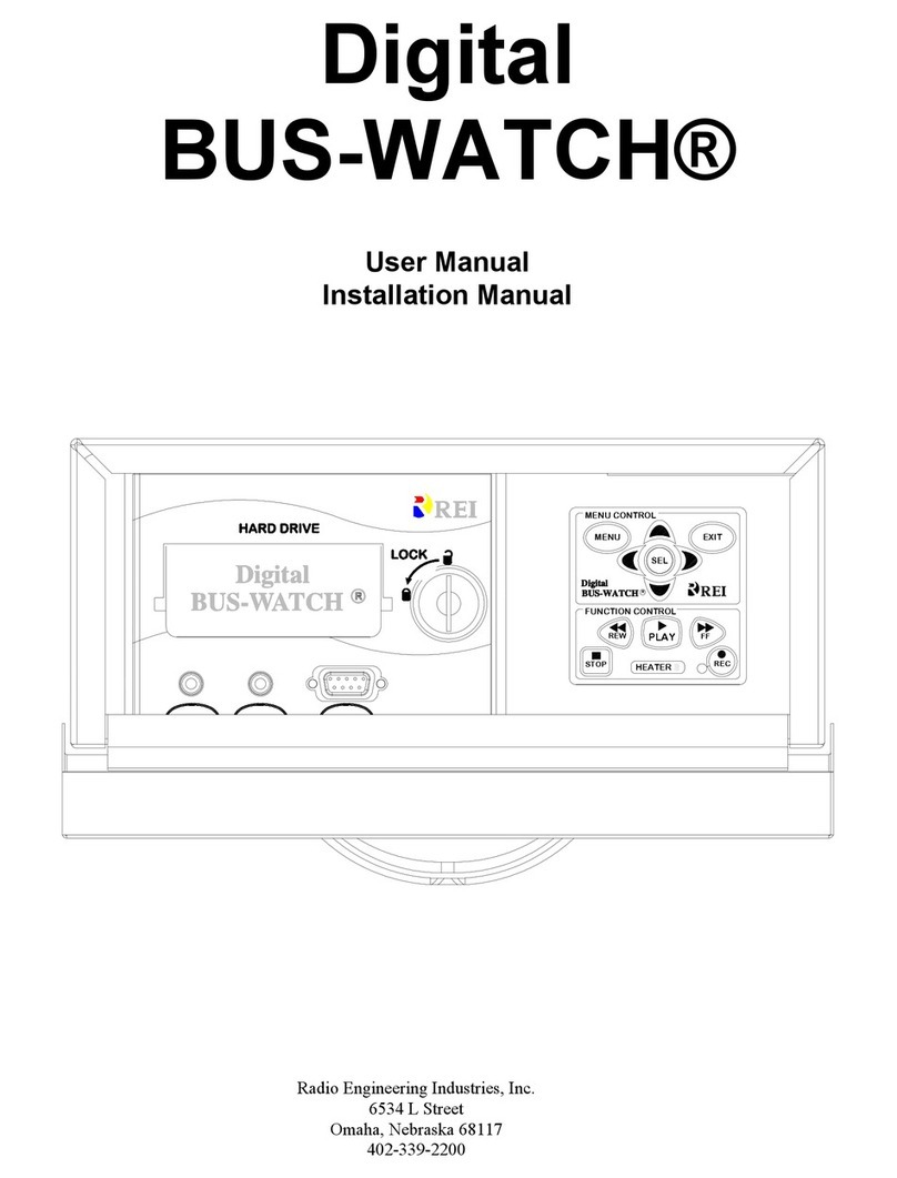
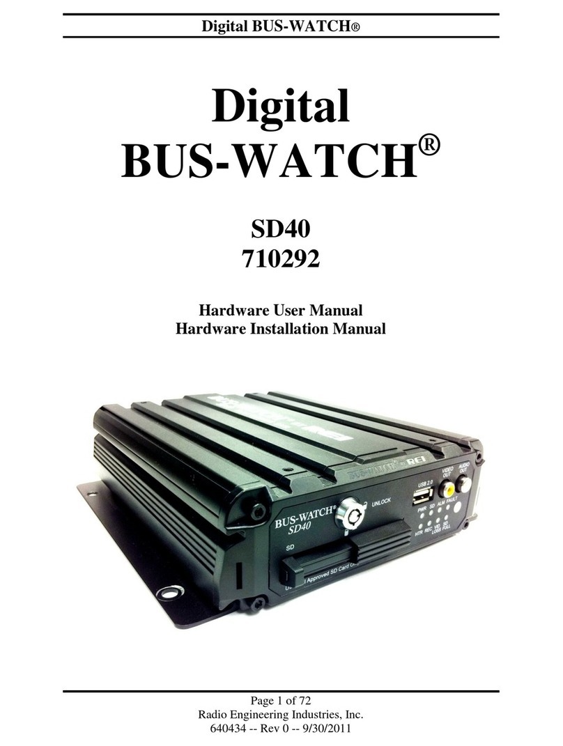
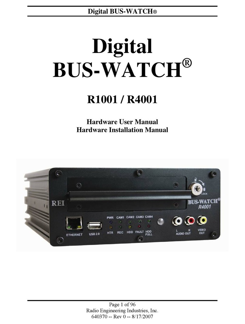
Radio Engineering Industries Digital BUS-WATCH User manual

Radio Engineering Industries, Inc.
6534 L Street
Omaha, Nebraska 68117
402-339-2200
Digital
BUS-WATCH®
User Manual
Installation Manual

Digital BUS-WATCH®
2
Radio Engineering Industries, Inc.
640333
Rev 0 -- 1/1/2006
Table of Contents
LIST OF FIGURES 4
INTRODUCTION 5
MAIN SYSTEM OVERVIEW 5
EXPANDED SYSTEMS OVERVIEW 6
REI DVR CAMERA SYSTEM OPTIONS 7
DVR FEATURES 8
System Components 8
Initial Set Up 8
Hard Drive Loading and Unloading 9
System Start-Up 9
Automatic Hard Drive Heater 9
Digital BUS-WATCH® IV Security Cabinet Mounting 10
Long Term Storage 10
SYSTEM INSTALLATION 11
System Wiring 11
Digital BUS-WATCH® IV External Record Indicator / Event Mark Button Harness 12
Digital BUS-WATCH® IV GPS Antenna Module Harness 13
Digital BUS-WATCH® IV Vehicle Sensor Options Harness DVR Connection Instructions 15
Speedometer Harness Wiring Instructions 15
Digital BUS-WATCH® IV Vehicle Sensor Options Harness Vehicle Connections 16
On-Screen Information with Vehicle Sensor Options Harness 16
Physical Mounting Requirements 17
Digital BUS-WATCH® IV Hanging Mount 17
Mount Conversion 19
Digital BUS-WATCH® IV Floor Mount Installation 19
Camera Placement 21
DIGITAL BUS-WATCH® IV BASIC OPERATION 22
Hard Disk Drive Modules 22
Front Panel 24

Digital BUS-WATCH®
3
Radio Engineering Industries, Inc.
640333
Rev 0 -- 1/1/2006
MENU SYSTEM 25
Main Menu Screen 26
System Information Screen 27
Set Time/Date Screen 28
Audio Control Menus 30
Audio Channel Selection Menu 31
Playback Volume Menu 31
Set Vehicle ID Screen 32
Calibration Screen 32
Speedometer Calibration Screen 33
Speedometer Signal Levels Screen 34
Screen Adjustment Screen 34
Center On-Screen Display 35
Adjust Width 36
Capture Image Screen 36
On Screen Display Options 40
Main Display Options 41
GPS Display Options 42
Vehicle Sensor Options 42
Sensor Display Options 43
Sensor Level Options 45
Playback Options 45
Recording Options 46
Overwrite Menu 48
Alarm Record Menu 49
Alarm Trigger Options 49
Alarm Record Options 50
Audible Alarm Options 51
Set Record Timers Screen 53
DIGITAL BUS-WATCH® IV CD-ROM 54
DIGITAL BUS-WATCH® IV SYSTEMS RELATED PART NUMBERS 55
TYPICAL CAMERA LENS VIEWING ANGLES 57
SPECIFICATIONS 58

Digital BUS-WATCH®
4
Radio Engineering Industries, Inc.
640333
Rev 0 -- 1/1/2006
LIST OF FIGURES
Figure 1 ……...………. BUS-WATCH® IV Components……...……...……...……...……...……...……....…. 5
Figure 2 ……...………. System Drawing ………………….……...……...……...……...……......…...……...… 6
Figure 3 ……...………. Camera System Options ...………….……...……...……...……...……...……...……. 7
Figure 4 ……...………. Initial Drive Warming Screen Shot …...……….……...……...……...…......……..... 10
Figure 5 ……...………. System Wiring ………………………...……...……...……...……...……......…...….. 12
Figure 6 ……...………. Event Harness Connection ..…..…………...……...……...……...……...……...….. 13
Figure 7 ……...………. GPS Antenna Harness Connection……….……...……...……...……...……...….... 13
Figure 8 ……...………. Vehicle Sensor Options Harness Mounting …………...……...……...……...…….. 14
Figure 9 ……...………. DVR Physical Mounting ……...……...……...……...……...……...……...…………. 17
Figure 10 …….....……. Under Seat Mounting ……….………...……...……...……...……...……...……....... 18
Figure 11 …….....……. DVR Cabinet Modification …………...……...……...……...……...……...……........ 19
Figure 12 …….....……. DVR Floor Mounting .…... ……...……...……...……...……...……...……...…........ 20
Figure 13 …….....……. Camera Connection and Placement .………………...……...……... ……...……... 21
Figure 14 ……...……… Potential Multiple Camera Placement Options .....…. ……...……...……...…...... 21
Figure 15 ……...……… Hard Drive Splash Page ..….……...……...……...……...……...……...…….....…. 23
Figure 16 ……...……… Front Panel Keypad ..…...………...……...……...……...……...……...……......….. 24
Figure 17 ……...……… Main Menu Screen Shot ..…….…………...……...……...……...……...……..…… 26
Figure 18 ……...……… System Information Page Screen Shot ……...……...……...……...…….....…….. 28
Figure 19 ……...……… Time/Date Menu Screen Shot ……...……...……...……...……...……...…........… 28
Figure 20 ……...……… 2006 DST Trigger Screen Shot ……...……...……...……...……...…….....…....... 29
Figure 21 ……...……... 2007 DST Trigger Screen Shot ..…….……...……...……...……...……......…....... 30
Figure 22 ……...……... Audio Control Menus Screen Shot ……...……...……...……...……...…....…........ 30
Figure 23 ……...……... Audio Channel Selection Menu Screen Shot ……...……...……...…….……....… 31
Figure 24 ……...……... Playback Volume Menu Screen Shot ……...……...……...……...……..……........ 31
Figure 25 ……...……... Set Vehicle ID Page Screen Shot ……...……...……...……...……......…...…….... 32
Figure 26 ……...……... Calibration Menu Screen Shot ……...……...……...……...……...……..……..…… 33
Figure 27 ……...……... Speedometer Calibration Page Screen Shot ……...……...…….....…...……...…. 33
Figure 28 ……...……... Speedometer Signal Levels Screen Shot ……...……...……...….....……....…..... 34
Figure 29 ……...……... Screen Adjustment Page Screen Shot ……...……...……...……..……...……...... 35
Figure 30 ……...……... Center OSD Page Screen Shot ……...……...……...……...……..……...……...… 35
Figure 31 ……...……... Adjust Screen Width Page Screen Shot ……...……...……......…...……...…….... 36
Figure 32 ……...……... Capture Image Page Screen Shot ……...……...……...……..……...……...……... 36
Figure 33 ……...……... PC Viewer Function Menu Screen Shot ……...……...…….……...…….....……... 37
Figure 34 ……...……... PC Remote Control Bar Screen Shot ……...……...……..……...……..…...…...… 38
Figure 35 ……...……... Remote Control Buttons Screen Shot ……..……………..…..……...……..……… 39
Figure 36 ……...……... On-Screen Display Options Screen Shot ……...……...…......……...……..……… 40
Figure 37 ……...……... Main Display Options Screen Shot ……...……...……...…….……...…..………… 41
Figure 38 ……...……... GPS Display Options Screen Shot ……...……...……...……..……...……...….…. 42
Figure 39 ……...……... Vehicle Sensor Options Screen Shot ……...……...……...…......……....…...……. 43
Figure 40 ……...……... Vehicle Sensor Display Options Screen Shot – School Bus Settings …....….…. 43
Figure 41 ……...……... Vehicle Sensor Display Options Screen Shot – Transit Settings …….....…….… 44
Figure 42 ……...……... Vehicle Sensor Display Options Screen Shot – Custom Settings …….......….… 44
Figure 43 ……...……... Vehicle Sensor Input Level Options Screen Shot ……..................……....…....… 45
Figure 44 ……...……... Playback Search Options Page Screen Shot ……...……...……...…….....…....… 46
Figure 45 ……...……... Recording Options Page Screen Shot ……...……...……...……...…….....…....… 46
Figure 46 ……...……... Hours of Recording Time with a 120 GB Hard Drive ……...……...……....…....… 47
Figure 47 ……...……... Overwrite Menu Screen Shot ……...……...……...……...……...……...…..…....… 48
Figure 48 ……...……... Alarm Recording Menu Screen Shot ……...……...……...……...……...……….… 49
Figure 49 ……...……... Alarm Trigger Options Screen Shot ……...……...……...……...…….........…....… 49
Figure 50 ……...……... Alarm Record Options Screen Shot ……...……...……...……...……...…..…….… 50
Figure 51 ……...……... Audible Alarm Options Screen Shot ……...……...……...……...…….........…....… 51
Figure 52 ……...……... Record Timers Page Screen Shot ……...……...……...……...……...…….…....… 53
Figure 53 ……...……... Typical Camera Lens Viewing Angles 4mm ..…...……...……...……........…….… 57
Figure 54 ……...……... Typical Camera Lens Viewing Angles 8mm ..…...……...……...……........…….… 57

Digital BUS-WATCH®
5
Radio Engineering Industries, Inc.
640333
Rev 0 -- 1/1/2006
INTRODUCTION
Thank you for purchasing the Digital BUS-WATCH® IV surveillance system by Radio
Engineering Industries, Inc. This manual is intended to provide the user with the
information required for proper installation, initial setup and explanation of the
individual programming options. If you have any questions, or need assistance,
please call:
SERVICE HOT LINE
USA & CANADA
1-877-726-4617 Toll Free
1-402-339-2200
MAIN SYSTEM OVERVIEW
The Digital BUS-WATCH® IV is a superior surveillance system specifically designed for
rugged school bus, mass transit, and all mobile applications. The system has smooth
audio playback on 2 separate channels at all frame rates, and is GPS enabled. The
system consists of an industrial grade Digital Video Recording system encased in a
tamperproof, lockable steel security cabinet and surveillance cameras of sturdy steel
housings. As an option, the Digital BUS-WATCH® IV can monitor and record vehicle
functions such as warning lamp operation, brake, vehicle speed, and two user defined
points. Figure 1 shows each component and a minimal hookup.
Figure 1

Digital BUS-WATCH®
6
Radio Engineering Industries, Inc.
640333
Rev 0 -- 1/1/2006
EXPANDED SYSTEMS OVERVIEW
Digital BUS-WATCH® IV surveillance systems are highly configurable. Figure 2 shows
a connection diagram for a fully equipped 4 camera system. To be able to switch
between different cameras based upon an external trigger (such as a door opening);
Camera Switch Devices (P/N 700462 or 710030) can be added to the system. Camera
Switch Devices and Quad Video Processors (Color P/N 700848) or (Black & White P/N
700483) can also be added to the system to be able to record and view 5 to 16 cameras
simultaneously.
Figure 2
VIDEOAUDIO
120-160GB VEHICLE SENSOR HARNESS (OPT)
CUSTOMER DETERMINES CONFIGURATION USED.
**THREE VIEWING CONNECTION OPTIONS SHOWN.
DESKTOP VIEWING STATION (OPT)
AV IN
**RCA CABLE - COMPOSITE A/V
VIDEO MONITOR (OPT)
LCD COLOR
690484
VARIOUS LENS SIZES
AVAILABLE
PENTIUM COMPUTER
**USB 2.0 CABLE
PORT
USB PORT
(OPT)
USB
**SERIAL COMMUNICATIONS CABLE (RS-232)
710005
PORT
COMM
EVENT RECORD MARK HARNESS (OPT)
SERIAL
511986
44 FT.
CAMERA CABLES
DIGITAL BUS-WATCH
FOUR OR MORE CAMERA SYSTEM
HARD DRIVE
WEDGE
OR
VARIOUS
AVAILABLE
SIZES
MODULE
DOME
OR
CAMERAS
STANDARD
POWER CABLE
512008 30 FT.
710000
DIGITAL BUS-WATCH
710010
GPS ANTENNA
*ADD CAMERA SWITCH
DEVICE(710030) OR QUAD
PROCESSOR (700848) FOR
ADDITIONAL CAMERAS

Digital BUS-WATCH®
7
Radio Engineering Industries, Inc.
640333
Rev 0 -- 1/1/2006
REI DVR Camera System Options
Table showing typical Digital BUS-WATCH® IV Systems for a variety of camera numbers
Figure 3
High Resolution: Full D1 (720x486)
Quarter Resolution: CIF (360x243)
Number of
Cameras
Digital BUS-WATCH®
System
Frames
Per
Second
Concurrent
Recorded Image
Resolutions
Typical Camera
Display Setup
4 Digital BUS-WATCH® IV 30 4 High
5 Digital BUS-WATCH® IV +
1 Camera Switch Device 30 4 High
6 Digital BUS-WATCH® IV +
2 Camera Switch Devices 30 4 High
7 Digital BUS-WATCH® IV +
1 Quad Video Processor 52.5 3 High +
4 Quarter
8
Digital BUS-WATCH® IV +
1 Quad Video Processor +
1 Camera Switch Device
52.5 3 High +
4 Quarter
9
Digital BUS-WATCH® IV +
1 Quad Video Processor +
2 Camera Switch Devices
52.5 3 High +
4 Quarter
10 Digital BUS-WATCH® IV +
2 Quad Video Processors 75 2 High +
8 Quarter
11
Digital BUS-WATCH® IV +
2 Quad Video Processors +
1 Camera Switch Device
75 2 High +
8 Quarter
12
Digital BUS-WATCH® IV +
2 Quad Video Processors +
2 Camera Switch Devices
75 2 High +
8 Quarter
13 Digital BUS-WATCH® IV +
3 Quad Video Processors 97.5 1 High +
12 Quarter
14
Digital BUS-WATCH® IV +
3 Quad Video Processors +
1 Camera Switch Device
97.5 1 High +
12 Quarter
15
Digital BUS-WATCH® IV +
2 Quad Video Processors +
2 Camera Switch Devices
97.5 2 High +
8 Quarter
16 Digital BUS-WATCH® IV +
4 Quad Video Processors 120 16 Quarter

Digital BUS-WATCH®
8
Radio Engineering Industries, Inc.
640333
Rev 0 -- 1/1/2006
DVR Features
•Search Video by Date, Hour, or External Event Triggers.
•On screen menu system for programming options.
•Hard drive heater to warm the hard drive to a safe operating temperature in
cold weather.
•Non-volatile ROM and battery backed-up memory.
•Ten 24-hr. programmable timers that are used to start and stop the recording
process without user (driver) intervention.
•Time and date are at the bottom of the picture so detail at the top of the picture
is not hidden.
•Electrically backward compatible with previous BUS-WATCH® models.
•Front panel keypad for easy programming of options and features.
•Audio and video jacks located on the front of Digital BUS-WATCH® IV for easy
access.
•Hot swappable Hard Drive Modules for easy video retrieval and less vehicle
down time.
System Components
•Industrial grade Digital Video Recorder.
•Hard Drive Module (120-160GB)
•Slide mount bracket (part of 710000 or 710000FM).
•Low light CCD cameras – Color, Black & White, or Decoy (4-16)
•Camera to Digital BUS-WATCH® IV cables – 510781 (or other length cables).
•Digital BUS-WATCH® IV cabinet power cable - 512002 (or other length cable).
•Vehicle Sensor Options Harness – 512008
•Event Record / External Record Indicator Harness – 511986 (or other length
cables).
•GPS Antenna - 710010
•Desktop Viewing Station - 710005
Initial Set Up
The Digital BUS-WATCH® IV system will operate without any user setup with the
default settings, however, it may not show the correct time and date (Factory Set
to Central Standard Time). To set the correct date and time and to program the
system operation to your requirements, please refer to the Menu section of this
manual.
When accessing the Menu, it is necessary to connect a video monitor to the Video
jack on the front of unit. REI recommends our battery-powered 5-inch Color LCD
monitor, P/N 690484.

Digital BUS-WATCH®
9
Radio Engineering Industries, Inc.
640333
Rev 0 -- 1/1/2006
Hard Drive Loading and Unloading
Inserting the Hard Drive: Turn the hard drive key to the unlocked and off
position. Gently insert the hard drive into the bay. Turn the hard drive key to the
locked and on position.
Removing the Hard Drive: Turn the hard drive key to the unlocked and on
position. Gently remove the hard drive from the bay.
Note: The Digital BUS-WATCH® IV will not function properly if the hard drive key is in
the unlocked or off positions. If there is no hard drive present in the bay but the key is in
the locked and on position, the Digital BUS-WATCH® IV will still power up normally, the
menus can be accessed, etc.; however, the unit will not be able to record any video and
the screen will read "DISK ERROR."
System Start-Up
To start the recording process, place the system switch in the ON position (this will
be done automatically if the system switch is connected to the ignition switch and
the ignition switch is in the ON position). Upon turning the system switch ON, the
Digital BUS-WATCH® IV will commence recording.
To stop the recording process, place the system switch in the OFF position. If the
OFF DELAY option is enabled, the Digital BUS-WATCH® IV will continue to
record for the prescribed number of minutes. When the off-delay expires, the
camera and Digital BUS-WATCH® IV shut off.
Automatic Hard Drive Heater
In order to prevent the possibility of hard-drive damage during cold periods, the
Digital BUS-WATCH® IV is equipped with a temperature sensor. The heater is
activated when the temperature is below 40° F and the Digital BUS-WATCH® IV
is turned on via system switch or timer. The red LED labeled HEATER on the front
panel indicates this. The colder the temperature, the longer the heater remains on,
with a maximum of ten minutes at the coldest temperatures. During this time all
Digital BUS-WATCH® IV functions are inhibited and the camera remains un-
powered. When the unit has completed its heating cycle, it will power up and
operate normally. As the temperature inside the unit drops during operation, the
heater will periodically come on to maintain a working operating temperature. The
unit can operate to temperatures below -80° F. A screen is displayed on the video
output jack on the front of the DVR displaying the temperature and the amount of
time left on the heater cycle, see figure 4. The DVR will use this time to attempt to
acquire GPS satellite signals if the GPS antenna is present in the system. A letter
‘H’ is present in the lower left hand corner of the screens whenever the hard drive
heater is on, unless that option is unselected in the Display Options Menu.

Digital BUS-WATCH®
10
Radio Engineering Industries, Inc.
640333
Rev 0 -- 1/1/2006
Initial Drive Warming Screen Shot
Figure 4
Digital BUS-WATCH® IV Security Cabinet Mounting
The Digital BUS-WATCH® IV security cabinet can be mounted in any orthogonal
orientation under a seat, in a parcel rack, on the floor, to a wall, etc. It should not
present a trip hazard or head impact hazard, nor should it interfere with the
seating, safety or comfort of the passengers. Horizontal orientation is suggested
when several installation options are available. Any other orientation besides
horizontal may slightly reduce the life of the hard drives, unless anti-shock and
vibration measures are taken during installation.
Long Term Storage
Although the Digital BUS-WATCH® IV system draws very little current in the
stand-by mode, if the system is installed but not used for an extended period of
time (longer than 2 weeks) it is recommended that the power be disconnected
from the DVR to avoid draining the vehicle battery. The DVR internal clock will
hold time and date for up to 10 years sitting on a shelf, and the daylight savings
time functions will kick in upon re-initialization when power is applied.

Digital BUS-WATCH®
11
Radio Engineering Industries, Inc.
640333
Rev 0 -- 1/1/2006
System Installation
System Wiring
Note: All cables should be hidden from view.
For the basic system (shown in Figure 5), there are five cables, one power (P/N 512002
– 16 Feet, or 512001 – 35 Feet) and 4 camera (P/N 510781 or any different length
cable). For external record indication, and alarm/event marking, the Record Indicator /
Event Mark Button Harness (P/N 511986) is available (shown in Figure 6). The GPS
Harness (P/N 710010) is used for satellite location and movement information (shown in
Figure 7). For additional vehicle monitoring, the BUS-WATCH® IV Vehicle Sensor
Options harness (P/N 512008) is available (shown in Figure 8)
Connect the camera(s) using cable P/N 510781, or equivalent. There is no specific
orientation for camera cables to be installed. If multiple types of cameras are installed
in a single system, be careful to note which cameras are located where. Use lenses
with more magnification (8mm) for to bring objects closer that are far away. Use lenses
with less magnification (4mm) for wide angle viewing.
Connect power using cable P/N 512002, or equivalent. The black wire connects to the
negative terminal of the battery. The green wire (labeled 12V Battery) connects directly
to the positive terminal of the battery. The green wire should be fused at 10 Amps if
using a 7 or more camera system with a Quad Video Processor (P/Ns 700483 or
700848). See Figure 5.
Connect any Quad Video Processors (P/Ns 700483 or 700848) or Camera Switching
Devices (P/N 700462 or 710030) as needed for multiple camera systems.
IF THE SYSTEM OPERATES IN THE MANUAL RECORD MODE, connect the red wire
(labeled 12V SW), to the switched side of the ignition switch. The red wire should be
fused at 1 A. The red wire is ignored if the system is in TIMER record mode.
WARNING
DISCONNECT VEHICLE BATTERY VOLTAGE BEFORE
INSTALLING SYSTEM WIRING
WARNING
DISCONNECT POWER TO THE DIGITAL BUS-WATCH® IV
BEFORE JUMP STARTING VEHICLE

Digital BUS-WATCH®
12
Radio Engineering Industries, Inc.
640333
Rev 0 -- 1/1/2006
System Wiring
Note: Green wire fused @ 7A; Red wire fused @ 1 A
Figure 5
INSTALLATION NOTE:
Exposed connectors may be placed inside of connector box on security cabinet.
Tampering could be further reduced by using metal conduit to route exposed wires into
vehicle body. All wires should be protected from the inside and outside areas of the
vehicle. Convoluted split loom should be used in all other areas to further protect the
wires. All wire connections should be splice soldered and insulated or lugged.
Digital Bus-Watch® IV External Record Indicator / Event Mark Button Harness
The Digital Bus-Watch® IV External Record Indicator / Event Mark Button
Harnesses come in 2 different types of switch, both in 2 different lengths. Reference
the Digital Bus-Watch® IV Systems Related Part Numbers – System Harnesses section
of this manual for specific part numbers. The 2 types of switches are OEM and
Aftermarket. The OEM switch is rectangular and fits into a standard size dashboard
knockout. The Aftermarket switch is round, for easier installation in vehicles without
spare switch knockouts. All four of these cables plug into the same port on the back of
the DVR. Reference Figure 6 for connection illustration.
*Connect GREEN wire DIRECTLY to the
positive terminal of the battery.
*Connect BLACK wire DIRECTLY to the
negative terminal of the battery.

Digital BUS-WATCH®
13
Radio Engineering Industries, Inc.
640333
Rev 0 -- 1/1/2006
External Record Indicator / Event Mark Button Harness Connection
Figure 6
Digital Bus-Watch® IV GPS Antenna Module Harness
The Digital Bus-Watch® IV GPS Antenna Module Harness plugs into the back of
the DVR as shown in Figure 7. Digital Bus-Watch® IV GPS Antenna Module will track
up to twelve satellites at a time while providing one-second navigation updates and low
power consumption. The GPS Antenna Module is housed in a black, water-resistant
case and designed to withstand rugged operating conditions. Information provided to
the DVR system include longitude, latitude, speed, heading, date, and time. Internal
memory backup allows the GPS Antenna Module to retain critical data such as satellite
orbital parameters, last position, date, and time to reduce valid data acquisition time.
GPS Antenna Harness Connection
Figure 7

Digital BUS-WATCH®
14
Radio Engineering Industries, Inc.
640333
Rev 0 -- 1/1/2006
PEDAL SWITCH
FROM BRAKE
FLASHER
FROM
FLASHER
FROM
FLASHER
FROM
FROM
FROM
FLASHER
FLASHER
Digital Bus-Watch® IV Vehicle Sensor Options Harness Vehicle Connection
Vehicle Sensor Options Harness Wiring
Figure 8
The BUS-WATCH® IV Vehicle Sensor Options Harness (shown in Figure 8)
connects to various locations in the vehicle to provide on-screen information
regarding vehicle performance. Many vehicles have different sets of signals that can
be monitored. Three levels of on-screen display are available to the installer: School
Bus, Transit, and Custom.
The default School Bus monitored points in the vehicle are:
•Vehicle speed
•Brake activation
•Amber warning lamp operation
•Red warning lamp operation
•Stop arm lamp operation
•Optional points with AUX 1 & AUX 2 (Aux 1 & Aux 2 are user-defined and
may be used to monitor points such as turn signals, rear and front doors, etc.)
The default Transit monitored points in the vehicle are:
•Vehicle speed
•Brake activation
•Warning lamp operation (De-acceleration Lights)
(Optional) Vehicle Sensor Options
Harness (Shown as School Bus)

Digital BUS-WATCH®
15
Radio Engineering Industries, Inc.
640333
Rev 0 -- 1/1/2006
•Turn signals
•Front door switch operation
•Back door switch operation
•Optional point with Auxiliary (Aux 1 is user-defined and may be used to
monitor points such as wheelchair lifts, inertia sensors, etc.)
The Custom vehicle sensor option allows for most other situations. The letters that
appear on the screen are settable through the menu system. The default settings are:
•Vehicle speed
•R - Red wires
•Y - Yellow wires
•L - Blue wire
•B - Brown wire
•W - White wire
•P - Purple wire
When using these options, the DEFAULT condition is that the Digital BUS-WATCH®
IV considers a low voltage (or ground) the OFF state. A high voltage (5-15 VDC) is
interpreted as the ON state. To switch the polarity of these signals, reference the
Vehicle Sensor Levels Options menu page as described in that section of the
manual.
BUS-WATCH® IV Vehicle Sensor Options Harness DVR Connection Instructions
Install the BUS-WATCH® IV Vehicle Sensor Option Harness (see Figure 8) into the
security cabinet.
1. Remove the 2 mounting screws connecting the conduit box to the DVR.
2. Insert the BUS-WATCH® IV Vehicle Sensor Options Harness by plugging it
into place.
3. Route the excess harness through the provided hole
4. Assemble the connector box back onto the DVR.
Speedometer Harness Wiring Instructions
The BUS-WATCH® IV speedometer input wires are designed to be spliced directly onto
the transmission speedometer transducer wires. In some installations, this may not be
possible (i.e. mechanical speedometer, transmission manufacturer warnings, etc.). The
BUS-WATCH® IV Vehicle Speed Sensor Kit (P/N 750086) may be required.
Refer to the vehicle service manual for speedometer type, exact wire
location, and transmission manufacturer warnin
g
s.

Digital BUS-WATCH®
16
Radio Engineering Industries, Inc.
640333
Rev 0 -- 1/1/2006
BUS-WATCH® IV Vehicle Sensor Options Harness Vehicle Connections
(Shown as School Bus)
WIRE COLOR WIRE DESCRIPTION
(2) YELLOW RIGHT & LEFT YELLOW WARNING LAMP BANK
(2) RED RIGHT & LEFT RED WARNING LAMP BANK
BLUE STOP ARM LAMP
BROWN BRAKE PEDAL LAMP
WHITE AUX SIGNAL 1
VIOLET AUX SIGNAL 2
Yellow Warning Lamps
Connect the YELLOW wires to each of the Warning Lamp Flashers’ Yellow lamp
outputs.
Red Warning Lamps
Connect the RED wires to each of the Warning Lamp Flashers’ Red lamp outputs.
Stop Arm Lamps
Connect the BLUE wire to the switched side of the top stop arm lamp.
Brake Lamp
Connect the BROWN wire to the switched side of one brake lamp.
On-Screen Information with BUS-WATCH® IV Vehicle Sensor Options Harness
The Digital BUS-WATCH® IV Surveillance system, when equipped with the BUS-
WATCH® IV Option Harness, will display information on-screen when the vehicle’s
monitored switches are activated and signals are applied to the monitored sensors.
ACTIVE SWITCH OR SIGNAL ON-SCREEN DISPLAY
BRAKE APPLIED B
STOP ARM DEPLOYED S
LEFT YELLOW WARNING LAMPS ON
(SEE NOTE 1)
* Y
RIGHT YELLOW WARNING LAMPS ON
(SEE NOTE 1)
Y *
LEFT RED WARNING LAMPS ON
(SEE NOTE 1)
* R
RIGHT RED WARNING LAMPS ON
(SEE NOTE 1)
R *
SPEEDOMETER
(SEE NOTE 2)
XX
MPH
NOTES:
1. The “*” symbols will alternately appear on each side of the “Y” or “R” in concert with the active lamp
bank.
2. The XXs represent the vehicle speed (i.e. 35).

Digital BUS-WATCH®
17
Radio Engineering Industries, Inc.
640333
Rev 0 -- 1/1/2006
Physical Mounting Requirements
There are two common ways to mount the Digital BUS-WATCH® IV. First is the
under-seat, or hanging, method. This method mounts the slide bracket to the
underside of a seat. Second is the floor-mount method. This method mounts the
Digital BUS-WATCH® IV to the floor of the bus. Figure 9 shows the minimum area
for the system installation.
DVR Physical Mounting
Figure 9
Digital BUS-WATCH® IV Hanging Mount
(See Figure 10)
1. Find a suitable location under the first seat behind the driver or under
the driver’s seat.
2. An area 15-1/2 inches should be unobstructed in front of the slide
bracket to allow sliding the security cabinet onto the slide bracket.
3. If necessary modify the positions of the tower, connector box, and slide
rails according to the instructions above.
4. Position the slide bracket on the frame of the seat in the desired
location. Drill 5/16th inch holes through the frame using the bracket as
a guide.
5. Attach slide bracket to seat frame using nuts and bolts.

Digital BUS-WATCH®
18
Radio Engineering Industries, Inc.
640333
Rev 0 -- 1/1/2006
Note:
Use clamps to attach slide bracket to the under-seat location if necessary.
Ensure stable mounting for proper DVR operation. DVR must be solid to vehicle frame.
Under Seat Mounting
Figure 10

Digital BUS-WATCH®
19
Radio Engineering Industries, Inc.
640333
Rev 0 -- 1/1/2006
Mount Conversion
Digital BUS-WATCH® IV Cabinet Modification
(See Figure 11)
Reverse the placement of the slide rails with screws and washers from top to
bottom of the Digital BUS-WATCH® IV.
DVR Cabinet Modification
Figure 11
Digital BUS-WATCH® IV Floor Mount Installation
Find a suitable location to mount the slide bracket on the floor. The Digital BUS-
WATCH® IV should not present a trip hazard or head impact hazard and should
not interfere with the seating, safety, or comfort of the passengers.
1. An area 15 and 1/2 inches should be unobstructed in front of the slide bracket
to allow sliding the Digital BUS-WATCH® IV onto the bracket.
2. Position the slide bracket on the floor and drill four 3/16th inch holes into the
floor using the mounting holes as a guide.
3. Set aside the slide bracket. Position four rubber shock mounts over the pilot
holes.
4. Place the slide bracket over the rubber shock mounts. Align the mounting holes
to the center of the shock mounts.
5. Secure slide bracket to the floor using four lag bolts.
6. Carefully slide the cabinet onto the slide bracket being sure to check alignment
of the connector. Lock to secure.

Digital BUS-WATCH®
20
Radio Engineering Industries, Inc.
640333
Rev 0 -- 1/1/2006
DVR Floor Mounting
Figure 12
Other manuals for Digital BUS-WATCH
1
This manual suits for next models
1
Table of contents
Other Radio Engineering Industries Security System manuals
Popular Security System manuals by other brands

Megalarm
Megalarm Mega 1100 Installation & operation instructions

Telguard
Telguard TG-7 Series Installation and operating guide

Defender
Defender DX-500 SOLAR quick start guide

Cisco
Cisco ISA 3000 Product documentation

Telco Sensors
Telco Sensors Space Guard Series user manual

Aprimatic
Aprimatic ET2-N 24 V LED quick start guide