Radio Engineering Industries Digital BUS-WATCH R1001 Instructions for use

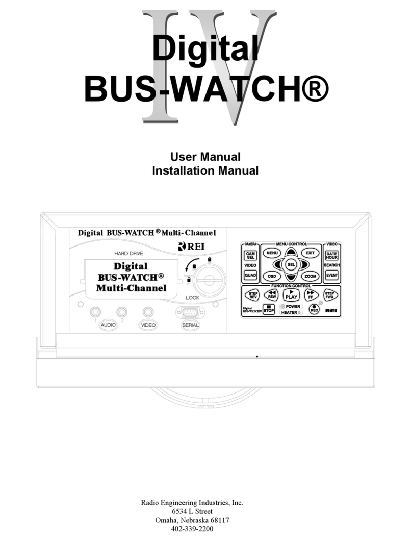
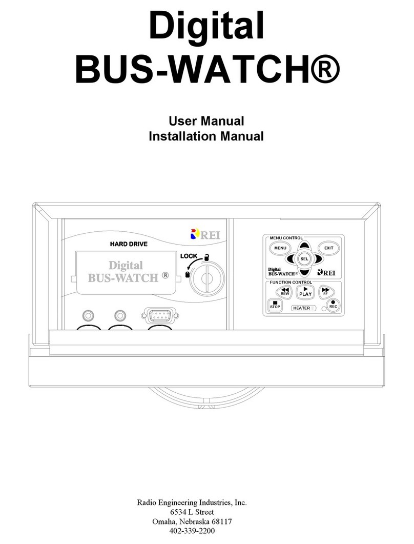
Digital BUS-WATCH®
Digital
BUS-WATCH®
R1001 / R4001
Hardware User Manual
Hardware Installation Manual
Page 1 of 96
Radio Engineering Industries, Inc.
640370 -- Rev 0 -- 8/17/2007

Digital BUS-WATCH®R1001 / R4001
Table of Contents
List of Figures.................................................................................................................... 4
Introduction....................................................................................................................... 6
Systems Overview .......................................................................................................... 8
Front and Back Panels .................................................................................................... 9
Remote Control............................................................................................................. 11
Initial Set Up................................................................................................................. 14
Removable Hard Drive Modules .................................................................................. 14
DVR Loading and Unloading............................................................................................... 14
Hard Drive Module Directory Structure............................................................................... 16
Hard Drive Record Times..................................................................................................... 17
USB Security Lockout.......................................................................................................... 18
Automatic Hard Drive Heater............................................................................................... 19
Long Term Storage ....................................................................................................... 19
Installation....................................................................................................................... 20
System Wiring – Power and Camera Cables ................................................................ 20
External Record Indicator / Event Mark Button Harness ............................................. 22
GPS Antenna Module Harness ..................................................................................... 23
Vehicle Sensor Options Harness................................................................................... 24
Speedometer Harness Wiring Instructions ........................................................................... 25
Vehicle Sensor Options Harness Vehicle Connections ........................................................ 25
Accelerometer Module Harness.................................................................................... 27
Physical Mounting Requirements................................................................................. 28
L Bracket Mounting.............................................................................................................. 28
Security Cabinet Mounting................................................................................................... 29
Camera Placement ........................................................................................................ 34
Typical Camera Lens Viewing Angles................................................................................. 37
Page 2 of 96
Radio Engineering Industries, Inc.
640370 -- Rev 0 -- 8/17/2007

Digital BUS-WATCH®R1001 / R4001
Table of Contents (continued)
Recording & Playback.................................................................................................... 39
System Start-Up............................................................................................................ 39
System Shut-Down ....................................................................................................... 39
Playback Options .......................................................................................................... 40
Menu Configuration....................................................................................................... 41
Installers Mode Page..................................................................................................... 41
Main Menu Page........................................................................................................... 42
System Setup ........................................................................................................................ 43
Time/Date Search ................................................................................................................. 80
Event Search ......................................................................................................................... 83
Advertising ........................................................................................................................... 84
Movies .................................................................................................................................. 85
Music .................................................................................................................................... 86
DVR Firmware Upgrading ............................................................................................ 87
Removable Hard Drive Module USB Firmware Upgrade............................................ 87
Front Panel USB Firmware Upgrade............................................................................ 88
Ethernet Firmware Upgrade.......................................................................................... 88
Systems Related Part Numbers ..................................................................................... 89
Troubleshooting Guide................................................................................................... 93
Specifications................................................................................................................... 96
Page 3 of 96
Radio Engineering Industries, Inc.
640370 -- Rev 0 -- 8/17/2007

Digital BUS-WATCH®R1001 / R4001
List of Figures
Figure 1: R1001/R4001 Expanded System Overview..................................................................... 8
Figure 2: Front Panel Layout........................................................................................................... 9
Figure 3: Front Panel Layout......................................................................................................... 10
Figure 4: DVR Remote Control .................................................................................................... 11
Figure 5: Remote Control Button Description .............................................................................. 12
Figure 6: Remote Control Navigation Arrows .............................................................................. 12
Figure 7: Remote Control Numeric Input Keys ............................................................................ 13
Figure 8: Removable Hard Drive Module Loading and Unloading.............................................. 15
Figure 9: Hard Drive Module Directory Structure ........................................................................ 16
Figure 10: Hard Disk Drive Module USB Security Lockout ........................................................ 18
Figure 11: System Wiring – Power and Camera Cables ............................................................... 21
Figure 12: External Record Indicator / Event Mark Button Harness Connection......................... 22
Figure 13: GPS Antenna Module Harness Connection ................................................................. 23
Figure 14: GPS Notification Icon.................................................................................................. 23
Figure 15: Vehicle Sensor Options Harness Connection .............................................................. 24
Figure 16: Accelerometer Module Harness Connection ............................................................... 27
Figure 17: 3 Axis Inertia Sensor Directions .................................................................................. 27
Figure 18: L Bracket Floor Mounting ........................................................................................... 28
Figure 19: REI’s Industrial Grade DVR Security Cabinet ............................................................ 29
Figure 20: Physical Mounting Clearance Requirements ............................................................... 30
Figure 21: Security Cabinet Under-Seat Mount............................................................................ 31
Figure 22: Security Cabinet Mount Conversion............................................................................ 32
Figure 23: Security Cabinet Floor Mounting ................................................................................ 33
Figure 24: Camera Connection and Placement ............................................................................. 34
Figure 25: Potential Single and Two Camera Placement Options ................................................ 35
Figure 26: Potential Multiple Camera Placement Options............................................................ 36
Figure 27: 4mm Lens Angles ........................................................................................................ 37
Figure 28: 8mm Lens Angles ........................................................................................................ 38
Figure 29: Connecting to the DVR with a Computer through the Ethernet Connection............... 40
Figure 30: Installers Mode Screen Shot ........................................................................................ 41
Figure 31: Main Menu Screen Shot............................................................................................... 42
Figure 32: System Setup Screen Shot ........................................................................................... 43
Figure 33: System – Date/Time Screen Shot................................................................................. 44
Figure 34: Custom DST Triggers.................................................................................................. 45
Figure 35: System – General Screen Shot..................................................................................... 46
Figure 36: System – Hard Disk Format – Start Screen Shot......................................................... 47
Figure 37: System – Hard Disk Format – Are You Sure? Screen Shot......................................... 48
Figure 38: System – Hard Disk Format – Formatting HDD Screen Shot ..................................... 48
Figure 39: System – Hard Disk Format – Formatting Successful Screen Shot............................. 48
Figure 40: System – Network Screen Shot.................................................................................... 49
Figure 41: System – Server Setup Screen Shot ............................................................................. 50
Figure 42: System – Security Screen Shot .................................................................................... 51
Figure 43: Security Password Setting Error Message ................................................................... 52
Figure 44: Security Password Screen Shot.................................................................................... 52
Page 4 of 96
Radio Engineering Industries, Inc.
640370 -- Rev 0 -- 8/17/2007

Digital BUS-WATCH®R1001 / R4001
List of Figures (continued)
Figure 45: Security DVR Unit ID Error Message ......................................................................... 52
Figure 46: Security DVR Password Error Message ...................................................................... 52
Figure 47: Security DVR Operator Password Correct Message ................................................... 52
Figure 48: Security DVR Administrator Password Correct Message ........................................... 52
Figure 49: System – USB Mode – Device Mode Screen Shot...................................................... 53
Figure 50: System – USB Mode – Host Mode Screen Shot.......................................................... 54
Figure 51: USB Host Mode – Upload Data Screen Shot .............................................................. 55
Figure 52: USB Host Mode – Flash Drive File List Screen Shot.................................................. 55
Figure 53: USB Host Mode – File Destination Screen Shot ......................................................... 56
Figure 54: USB Host Mode – Copying File Message ................................................................... 56
Figure 55: USB Host Mode – Copy Successful Message ............................................................. 56
Figure 56: USB Host Mode – Restart Messages ........................................................................... 56
Figure 57: System – Driver Information Screen Shot ................................................................... 57
Figure 58: Data Entry Keyboard Screen Shot ............................................................................... 58
Figure 59: System – Audible Alerts Screen Shot.......................................................................... 59
Figure 60: System – Default Setup – Warning Screen Shot.......................................................... 60
Figure 61: System – Default Setup – Restoring Screen Shot ........................................................ 61
Figure 62: System – Configuration Setup – Save Successful Screen Shot ................................... 62
Figure 63: Camera Menu Screen Shot........................................................................................... 63
Figure 64: Camera – 4 Camera Recording Parameters Screen Shot ............................................ 64
Figure 65: Record Parameter Group Resources ............................................................................ 65
Figure 66: Camera – 1 Camera Recording Parameters Screen Shot ............................................. 66
Figure 67: Camera – 2 Cameras Recording Parameters Screen Shot............................................ 66
Figure 68: Camera – Camera Name Screen Shot.......................................................................... 67
Figure 69: System Setup – Schedule Screen Shot......................................................................... 68
Figure 70: Event Setup – Sensor Screen Shot ............................................................................... 69
Figure 71: Event Setup – Sensor – IO Input – School Bus Screen Shot ....................................... 70
Figure 72: Event Setup – Sensor – IO Input – Transit Bus Screen Shot....................................... 71
Figure 73: Event Setup – Sensor – IO Input – Custom Screen Shot ............................................. 72
Figure 74: Event Setup – Sensor – Accelerometer Screen Shot.................................................... 73
Figure 75: Event Setup – Sensor – Speedometer Screen Shot ...................................................... 74
Figure 76: Event Setup – Event Record Mode Screen Shot.......................................................... 75
Figure 77: System Setup – System Information Screen Shot........................................................ 76
Figure 78: System Information – HDD Information Screen Shot................................................. 77
Figure 79: System Information – System Information Screen Shot.............................................. 78
Figure 80: System Information – Maximum Accelerometer Readings Screen Shot..................... 79
Figure 81: Time/Date Search – Date Selection Screen Shot ......................................................... 80
Figure 82: Time/Date Search – Available Video Calendar Screen Shot....................................... 81
Figure 83: Time/Date Search – File Selection Screen Shot .......................................................... 82
Figure 84: Event Search Screen Shot ............................................................................................ 83
Figure 85: Advertisement Screen Shot.......................................................................................... 84
Figure 86: Movie Playback Screenshot......................................................................................... 85
Figure 87: Music Playback File Selection Screen Shot................................................................. 86
Figure 88: Firmware Upgrading In Progress Screen Shot............................................................. 87
Figure 89: Firmware Upgrade Success Screen Shot ..................................................................... 88
Page 5 of 96
Radio Engineering Industries, Inc.
640370 -- Rev 0 -- 8/17/2007

Digital BUS-WATCH®R1001 / R4001
Introduction
All of us at REI would like to thank you for purchasing a Digital BUS-
WATCH® surveillance system by Radio Engineering Industries, Inc. This manual is
intended to provide the user with the information required for proper installation,
initial setup and explanation of the individual programming options. If you have any
questions, or need assistance, please call:
SERVICE HOT LINE
USA & CANADA
1-877-726-4617 Toll Free
1-402-339-2200
The R1001 and R4001 are a series of cost effective, fanless, embedded Mobile
DVR PC platform solutions supporting up to 4 camera inputs. These systems come with
a unique compact rugged design to meet the demands of harsh mobile environments.
These mobile DVR feature the latest technologies including Removable USB Hard Disk
Drive Modules, Ethernet, and GPS. The R1001/R4001 have the ability to perform DVR
functions for safety and security purposes, along with managing a Media Advertisement
System for education, entertainment, or to create extra value added services for all public
and commercial transportation in the current and future markets.
Features:
●Ultra compact extruded aluminum housing, low weight, high temperature
and vibration resistance.
●Low-voltage, low-current architecture designed for harsh mobile environments.
●USB Removable hard drive modules with tamper resistant lock and secure
controls.
●All DVRs fully support NTSC and PAL, Fahrenheit and Celsius, KM/H and
MPH.
●Communications are supported through a TCP / IP network interface and a
USB connection to PCs.
●Each DVR comes with a hand-held IR remote control with On-Screen Display
(OSD) for configuration and control of the DVR.
●The DVR features a 2.5" Removable Mobile HDD Module with internal anti-
vibration and shock resistance.
●4 channels for video input, full-motion (30fps/camera) continuous video
recording and display 4 channels for high-fidelity, digitally recorded, 4
independent synchronized audio channels matched to 4 independent video
channels.
Page 6 of 96
Radio Engineering Industries, Inc.
640370 -- Rev 0 -- 8/17/2007

Digital BUS-WATCH®R1001 / R4001
●Secure, constant recording while system is powered with event bookmarks for
easy event searching.
●The DVR utilizes MPEG-4 video compression for high video quality, low
storage requirements, and long record times.
●User-selectable settings for quality and audio record enable / disable for each
video channel
●Multi-level password protection for settings, playback, remote access, and more.
●Integrated and filtered power supply for cameras, sensors, relays and other
accessories.
●Selectable idle frame rate with event-triggered burst recording speeds up to
30fps / camera.
●Multiple alarm inputs with selectable pre-alarm and post-alarm recording.
●Full event logging of every operation controlled by the DVR.
●TV output channel for recorded, live, and advertising video.
Video Viewing
●Streaming video output for advertising, entertainment, and information
●DVD-quality steaming audio / video channel with independent NTSC or PAL
television output
●Convenient HDD, USB, or TCP / IP media updating and status file
downloading
●Simultaneous and independent operation of DVR and streaming advertising.
Video Retrieval and Archiving:
●The DVR has Ethernet and USB ports on the front panel for easy video retrieval
on the vehicle with a notebook computer.
●The DVR has two sets of RCA Video and Stereo Audio outputs for monitor
viewing on the vehicle.
●The DVR and Removable Hard Drives both have USB 2.0 connections for fast
file transfer utilizing PC-based file formats.
●Easy to use PC-Based software application for playback, file transfer, archiving
management, and video file format conversion.
●Vehicle management PC software interprets audio, video, and vehicle data for
driver and vehicle use assessment.
●Video event search software allows intelligent searching of video based on
event information.
Supplemental Data and Driver Management Modules:
●External GPS antenna module for embedded digital information of GPS
location, speed, heading, and time.
●External 3-axis inertia sensor for embedded digital information or trigger of
video-matched motion events for accident reconstruction.
Page 7 of 96
Radio Engineering Industries, Inc.
640370 -- Rev 0 -- 8/17/2007

Digital BUS-WATCH®R1001 / R4001
Systems Overview
SIZES
AVAILABLE
AUDIO
VIDEO
ACCELEROMETER MODULE
20 FT.
ALARM/PANIC CABLE
VEHICLE SENSOR HARNESS (OPT)
AVAILABLE
VARIOUS LENS SIZES
710144
20 FT.
**RCA CABLE - COMPOSITE A/V
COMPUTER
(OPT)
USB
PORT
AV IN
512196
USB
2.0
(OPT)
ETHERNET CABLE
GPS RECEIVER
511617
530068
710143
511986
3 FT.
(OPT)
USB 2.0 CABLE
(COMES W/MONITOR)
VIDEO MONITOR (OPT)
690484
LCD COLOR
FLASH
USB
(OPT)
DRIVE
REMOTE
80-160 GB
**ADD CAMERA SWITCH DEVICE
(710030) FOR MORE THAN 4 CAMERAS
R1001/R4001 MOBILE DVR SYSTEMS
*CAMERA CABLES
(VARIOUS LENGTHS AVAILABLE)
DIGITAL BUS-WATCH
OR
DOME
SLIM-LINE
OR
OR
WEDGE
STANDARD
CAMERAS
CAMERAS 2, 3, & 4
ARE NOT
APPLICABLE WITH
R1001 DVR SYSTEM.
LOCK BOX
*710134
4 CH DIGITAL BUS-WATCH
(VARIOUS LENGTHS AVAILABLE) CAMCAMCAMCAM
ACC
POWER
TRIGGER
VIEW
TRIGGER
REAR
SENSORS
AUDIOOUT
GPS SENSORS CAM1 CAM2 CAM3 CA M4ACC
GPS
POWER
OUT
RVIDEO
FC
C
ICP
L
1234
POWER CABLE
HDDHDD FAULTRECHTR
ETHERNET USB 2.0 FULL
CAM1
PWR CAM4CAM2 CAM3
VIEW
RVIDEOLOUT
AUDIOOUT
FRONT
VARIOUS
MODULE
HARD DRIVE
(OPT)
NOTE:
R
710133
Figure 1: R1001/R4001 Expanded System Overview
Page 8 of 96
Radio Engineering Industries, Inc.
640370 -- Rev 0 -- 8/17/2007

Digital BUS-WATCH®R1001 / R4001
Front and Back Panels
VIDEO OUTPUT CONNECTION
AUDIO OUTPUT CONNECTIONS, R AND L
LED STATUS INDICATORS
USB 2.0 CABLE CONNECTION
ETHERNET CABLE CONNECTION
HARD DRIVE BAY
5
6
4
3
2
1
1
46
5
3
2
USB 2.0ETHERNET HDDHTR REC FULL
FAULT HDD
CAM2PWR CAM1 CAM4CAM3
AUDIO OUT
RL OUT
VIDEO
7
FRONT PANEL LAYOUT
7HARD DRIVE LOCK
Figure 2: Front Panel Layout
Page 9 of 96
Radio Engineering Industries, Inc.
640370 -- Rev 0 -- 8/17/2007

Digital BUS-WATCH®R1001 / R4001
OUTAUDIO OUT
RVIDEO
REAR PANEL LAYOUT
POWER LICP
C
VIDEO OUTPUT CONNECTION
CAMERA INPUTS (CAM1 ON R1001 MODEL; CAM 1-4 ON R4001 MODEL)
SENSORS (VEHICLE SENSOR CABLE CONNECTION)
GPS (GPS RECEIVER CONNECTION)
ACC (ACCELEROMETER MODULE CONNECTION)
TRIGGER (ALARM/PANIC CABLE CONNECTION)
POWER CABLE CONNECTION
AUDIO OUTPUT CONNECTIONS, R AND L
10
14
15
12
13
11
9
8
8FC
13
CAM3
1211109
GPSTRIGGER ACC SENSORS CAM1 CAM2
1514
Figure 3: Front Panel Layout
Page 10 of 96
Radio Engineering Industries, Inc.
640370 -- Rev 0 -- 8/17/2007

Digital BUS-WATCH®R1001 / R4001
1POWER Turn DVR On/Off
LABEL FUNCTIONI.D.
2"1" through "4" Select Camera
3NEXT Volume UP
4REW Playback Function, X2, X4
5PREV Volume DOWN
6
LOGIN/LOCK Access Menu
7
"0" Quad Screen
8
ENTER Installers Mode
9
FWD Playback Function, X2, X4
10
SETUP Menu
11
EXIT Exit
Numeric
12
Playback Functions
Figure 5: Remote Control Button Description
Use the ARROW keys to
move between selections,
input fields and icons. Press
ENTER to select and EXIT to
return. NEXT and PREV is
also used to increase or
decrease volume.
NAVAGATION ARROWS
Figure 6: Remote Control Navigation Arrows
Page 12 of 96
Radio Engineering Industries, Inc.
640370 -- Rev 0 -- 8/17/2007

Digital BUS-WATCH®R1001 / R4001
NUMERIC INPUT KEYS
Use the numbers to input
values in the system setup
screen or switch through the
channels in live and playback
modes.
Figure 7: Remote Control Numeric Input Keys
Page 13 of 96
Radio Engineering Industries, Inc.
640370 -- Rev 0 -- 8/17/2007

Digital BUS-WATCH®R1001 / R4001
Initial Set Up
The Digital BUS-WATCH® system will operate without any user setup
with the default settings, however, it may not show the correct time and date
(Factory Set to Central Standard Time). To set the correct date and time and to
program the system operation to your requirements, please refer to the Menu
Configuration section of this manual.
When accessing the Menu, it is necessary to connect a video monitor to
the Video jack on the front or back of the unit. REI recommends our battery-
powered 5-inch Color LCD monitor, P/N 690484.
Removable Hard Drive Modules
DVR Loading and Unloading
Inserting the Hard Drive: Turn the hard drive key to the unlocked and
off position. Insert the hard drive into the bay. Turn the hard drive key to
the locked and on position, as shown in Figure 8 on Page 15.
Removing the Hard Drive: Turn the hard drive key to the unlocked and
off position. Gently remove the hard drive from the bay.
Note: The Digital BUS-WATCH® R1001 & R4001 will not function
properly if the hard drive key is in the unlocked or off positions. If there is
no hard drive present in the bay but the key is in the locked and on
position, the Digital BUS-WATCH® will still power up normally, the
menus can be accessed, etc.; however, the unit will not be able to record
any video.
Page 14 of 96
Radio Engineering Industries, Inc.
640370 -- Rev 0 -- 8/17/2007

Digital BUS-WATCH®R1001 / R4001
Figure 8: Removable Hard Drive Module Loading and Unloading
Page 15 of 96
Radio Engineering Industries, Inc.
640370 -- Rev 0 -- 8/17/2007

Digital BUS-WATCH®R1001 / R4001
Hard Drive Module Directory Structure
Figure 9: Hard Drive Module Directory Structure
The Directory structure of the Removable Hard Drive Module is shown in Figure 9 above.
Listed below are the general purposes of the files and folders.
ads: The folder for advertising files.
ads_log: The folder for the advertising logs.
alarm1: The folder with the recorded video associated with alarms.
bak: For internal DVR use only.
movie: The folder for movie files.
music: The folder for music files.
record: The folder with the recorded video.
Recycled: Windows file.
ReportStation: Future use.
Stationblank: Future use
tmp: For internal DVR use only.
dvdplayermsg: For internal DVR use only.
RecordInfo.log: For internal DVR use only.
time.bin: For internal DVR use only.
Page 16 of 96
Radio Engineering Industries, Inc.
640370 -- Rev 0 -- 8/17/2007

Digital BUS-WATCH®R1001 / R4001
Hard Drive Record Times
1 Camera with a 160GB Hard Drive (in Hours)
D1
FPS
Quality 30 15 8 4 2 1
1 92 184 372 748 1496 2992
2 104 208 416 836 1672 3344
3 116 236 472 944 1892 3788
4 136 272 544 1092 2184 4372
5 160 320 644 1292 2584 5168
6 196 392 788 1576 3156 6316
7 252 504 1012 2028 4060 8120
8 352 708 1420 2840 5684 11368
HD1
FPS
Quality 30 15 8 4 2 1
1 184 372 748 1496 2992 5984
2 208 416 836 1672 3344 6688
3 236 472 944 1892 3788 7580
4 272 544 1092 2184 4372 8744
5 320 644 1292 2584 5168 10336
6 392 788 1576 3156 6316 12632
7 504 1012 2028 4060 8120 16244
8 708 1420 2840 5684 11368 22740
CIF
FPS
Quality 30 15 8 4 2 1
1 252 504 1012 2028 4060 8120
2 296 592 1184 2368 4736 9472
3 352 708 1420 2840 5684 11368
4 444 888 1776 3552 7104 14212
5 592 1184 2368 4736 9472 18952
6 708 1420 2840 5684 11368 22740
7 888 1776 3552 7104 14212 28424
8 1012 2028 4060 8120 16244 32492
32492 hours = 3 years, 8 months, & 18 days of constant 24 hour recording.
Page 17 of 96
Radio Engineering Industries, Inc.
640370 -- Rev 0 -- 8/17/2007
Digital BUS-WATCH®R1001 / R4001
USB Security Lockout
USB A-B CABLE
PENTIUM COMPUTER
USB
PORT
HDD
REAR VIEW
USB
2.0 PORT
(B)
(A)
GREEN
DOT
NOTE LOCK
POSITION
Figure 10: Hard Disk Drive Module USB Security Lockout
The REI Removable Hard Drive Modules come with an enhanced
security feature that allows the property to lock out the USB port on the
back of the module, as shown in Figure 10 above. This feature allows
another level of protection, in addition to chain of custody, to ensure that
the information stored on the drive will not be tampered with or erased.
When the keylock on the back of the DVR is switched into the green dot
position, the USB port functions normally and the hard drive will be
recognized by a PC as an external USB hard drive. When the keylock is
switched into the red dot position, the USB port is disabled and a
computer will not be able to access the files stored on the drive.
Regardless of the position of the keylock switch, the DVR is always able
to access the drive, so the switch can be left in the red dot (USB off)
position during normal DVR operation with no adverse effects. In this
situation, the hard drive USB keys can be safely kept with the proper
personnel for added assuredness of video evidence integrity.
Page 18 of 96
Radio Engineering Industries, Inc.
640370 -- Rev 0 -- 8/17/2007
Digital BUS-WATCH®R1001 / R4001
Automatic Hard Drive Heater
In order to prevent the possibility of hard-drive damage during
cold periods, the Digital BUS-WATCH® is equipped with a
temperature sensor. The heater is activated when the temperature is
below 40° F and the Digital BUS-WATCH® is turned on via system
switch or timer. The red LED labeled HTR on the front panel indicates
this. The colder the temperature, the longer the heater remains on, with
a maximum of fifteen minutes at the coldest temperatures. When the
unit has completed its heating cycle, it will restart and operate
normally. As the temperature inside the unit drops during operation,
the heater will periodically come on to maintain a working operating
temperature. The unit can operate to temperatures below -40° F. The
menus and the Installers Mode are still operational during the Initial
Drive Warming Period.
Long Term Storage
Although the Digital BUS-WATCH® systems draw very little current
in the stand-by mode, if the systems are installed but not used for an extended
period of time (longer than 2 weeks) it is recommended that the power be
disconnected from the DVR to avoid draining the vehicle battery. The DVR
internal clock will hold time and date for up to 10 years sitting on a shelf, and
the daylight saving time functions will kick in upon re-initialization when
power is applied.
Page 19 of 96
Radio Engineering Industries, Inc.
640370 -- Rev 0 -- 8/17/2007

Digital BUS-WATCH®R1001 / R4001
Installation
WARNING
DISCONNECT VEHICLE BATTERY VOLTAGE BEFORE INSTALLING
SYSTEM WIRING
WARNING
DISCONNECT POWER TO THE DIGITAL BUS-WATCH® BEFORE
JUMP STARTING VEHICLE
WARNING
INSTALL DVR HORIZONTALLY. USE EXTERNAL SHOCK AND
VIBRATION DAMPENING IF NEEDED.
System Wiring – Power and Camera Cables
Note: All cables should be hidden from view.
For the basic system (shown in Figure 11 on Page 21), there are five
cables, one power (P/N 512002 – 16 Feet, or 512001 – 35 Feet) and 4 camera
(P/N 510993 or any different length cable). For external record indication and
alarm/event marking, the Record Indicator / Event Mark Button Harness (P/N
511986) is available (shown in Figure 12 on Page 22). The GPS Harness (P/N
710144) is used for satellite location and movement information (shown in Figure
13 on Page 23). For additional vehicle monitoring, the BUS-WATCH® Vehicle
Sensor Options harness (P/N 512008) is available (shown in Figure 15 on Page
24).
Connect the camera(s) using cable P/N 510781, or equivalent. There is no
specific orientation for camera cables to be installed. If multiple types of cameras
are installed in a single system, be careful to note which cameras are located
where. Use lenses with more magnification (8mm) for to bring objects closer that
are far away. Use lenses with less magnification (4mm) for wide angle viewing.
Connect power using cable P/N 512002, or equivalent. The black wire
connects to the negative terminal of the battery. The white wire (labeled 12V
Battery) connects directly to the positive terminal of the battery. The red wire
Page 20 of 96
Radio Engineering Industries, Inc.
640370 -- Rev 0 -- 8/17/2007
This manual suits for next models
1
Table of contents
Other Radio Engineering Industries Security System manuals
Popular Security System manuals by other brands

LY-TECH
LY-TECH LY-GSM300KIT user manual

Assa Abloy
Assa Abloy Premium Plus HSA6410 Installation, Programming, Operating Manual

Infotel
Infotel M60 operating instructions

SkyLink
SkyLink Monitoring Station MS-200 owner's manual

HENGBO
HENGBO HB-2020 Series user manual

Enuresis Solutions
Enuresis Solutions DryBuddy 2 quick start guide