Technical Specifications and FCC Regulations
10
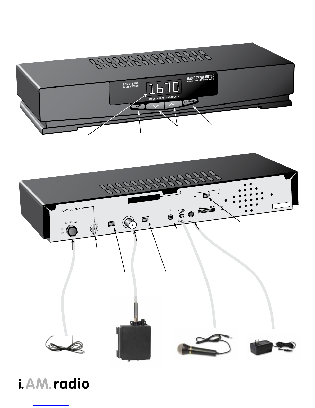
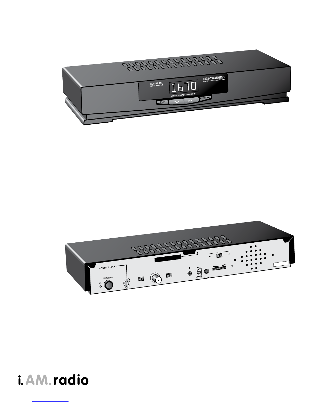
Model 5.0 i.AM. - AM Radio Transmitter
• Frequency Agile with front-panel selectability - frequency range: 520 to 1700 kHz
• Automatic Tuning – internal automatic servo-operated tuning circuit for range maximization
(U.S. Patent No. 6,295,443)
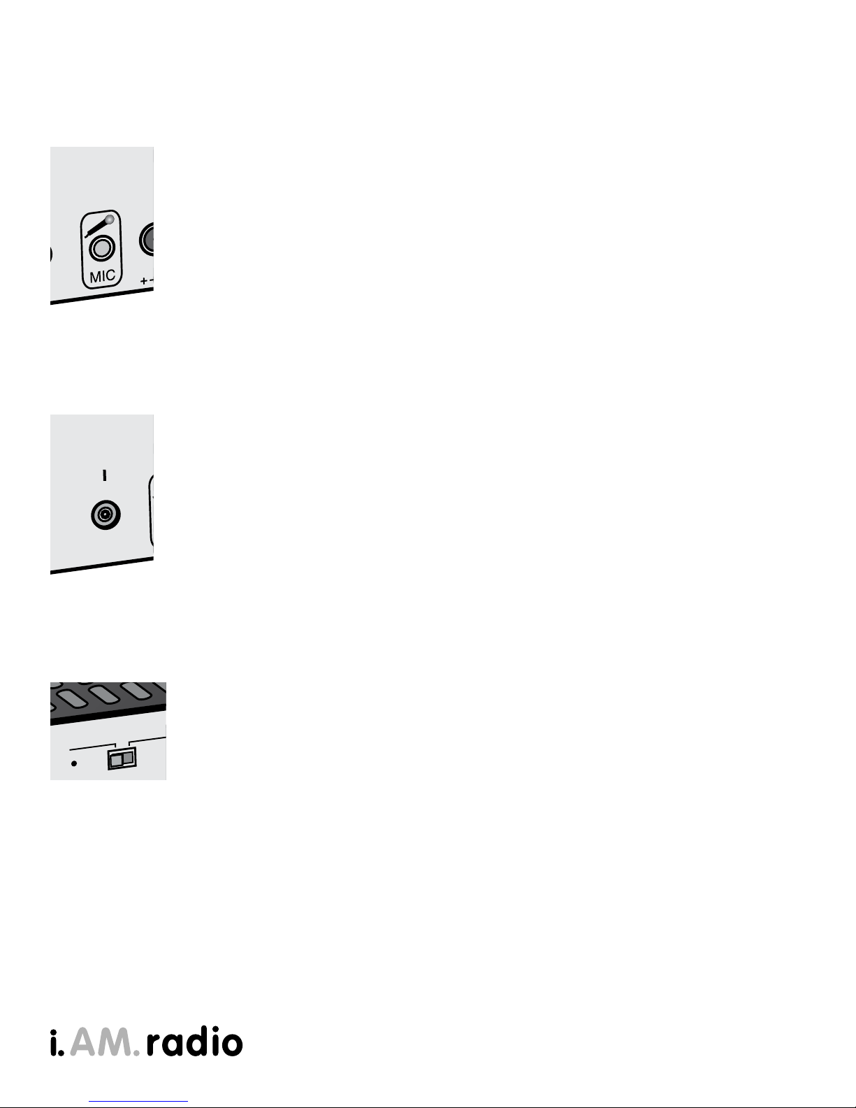
• Audio Inputs – internal microphone plus externa mic (mono) and line level (stereo) inputs
(on 1/8” “mini phone” connector-line level sensitivity .1 to .5 volts
• Audio Processing: built in automatic audio limitor / compressor
• Message Storage: digital voice record/playback solid state memory chip, 5 minutes max.
• Message Length: variable depending upon model of transmitter (see sticker on unit back panel)
• Microphone: built-in or hand-held
• Size: 8” x 14” x 2.5” (shipping size boxed - 12” x 20” x 6”)
• Weight: 4 lbs. (shipping weight - 7 lbs)
• Indoor Antenna: black, rubberized wire, approximately 8’ in length
• Power: 110/120VAC via included 18VDC 100mA external transformer / grounded AC plug adapter
• RF output power: 100 mW average
• Frequency Control: Crystal controlled phase locked loop tuner
• Frequency Stability: - +/- 30 Hz
• Range: typically 300-3000 feet (dependent on conditions and use of outdoor range extender
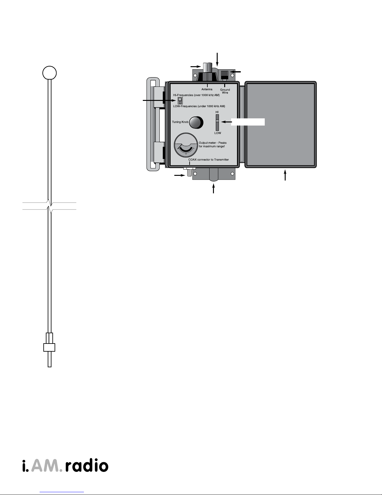
Model ATU – Outdoor tuning Unit / Range Extender
• Input Power: .01 mW to 1 watt
• Frequency Range: 520 to 1700 kHz
• Connectors: “F” type input, 3/8”-24 threaded antenna coupling, grounding post with knurled knob
• Radiator: 9’ fiberglass whip antenna (included)
• Internal controls: frequency range switch, tuning knob
• Internal indicator: signal strength meter
• Size: 5” x 7” x 3” (shipping size boxed - 6” x 8.5” x 4”)
• Weight: 1.5 lbs. (shipping weight - 2 lbs)
• Mounting: mounts to any metal pipe from 1/2” to 1 3/4” diameter (mounting brackets included,
pipe not included
• US Patent Number US 7, 437,130 B2
Applicable FCC and Licence Regulations - FCCID: DLB5LTT98
This device complies with Part 15 of the FCC rules. Operation is subject to the following two conditions:
1.) This device may not cause harmful interference, and 2.) this device must accept any interference
received, including interference that may cause undesired operation.
The model ATU Outdoor Manual Antenna Tuning unit is FCC accepted within this certification as serving as
the final output stage.
FCC part 15 rules, Section 15.219 Operation in the band 510–1705 kHz.
(a) The total input power to the final radio frequency stage (exclusive of filament or heater power) shall not
exceed 100 milliwatts.
(b) The total length of the transmission line, antenna and ground lead (if used) shall not exceed 3 meters.
(c) All emissions below 510 kHz or above 1705 kHz shall be attenuated at least 20 dB below the level of
the unmodulated carrier. Determination of compliance with the 20 dB attenuation specification may be
based on measurements at the intentional radiator’s antenna output terminal unless the intentional
radiator uses a permanently attached antenna, in which case compliance shall be demonstrated by
measuring the radiated emissions.