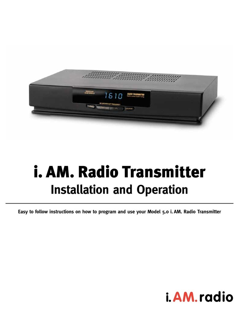
Radio Systems TR-6000 User manual

Radio Systems
TR-6000 10 WATT
AM Broadcast Transmitter
Operating Instructions
601 Heron Drive • Logan Township, NJ 08085
Phone: 856-467-8000 • Fax: 856-467-3044
www.radiosystems.com

Radio Systems TR-6000 AM BROADCAST TRANSMITTER
Radio Systems TR-6000 AM BROADCAST TRANSMITTER Page 2
Radio Systems TR-6000 AM Broadcast Transmitter
Operation Manual
Radio Systems TR-6000 AM Broadcast Trasnmitter — Part # MAN-TR6000
Manual Revision 04-04-2012
To reflect new packaging with thin front panel controls and 1 r.u. (1 3/4”) rack mount capability.
For serial numbers 102099 and higher
Copyright 2012 by Radio Systems Design, Inc. All rights reserved. Radio Systems Design, Inc. reserves specication
privileges. Information in this manual is subject to change without notice.
Technical support: +1-856-467-8000 or [email protected]

Radio Systems, Inc. TR-6000 Manual
P a g e 3
Table Of Contents
Specications ...................................................................................................................... 4
Operating Instructions ........................................................................................................ 5
Overview.........................................................................................................................................5
Available Options ..........................................................................................................................5
Front Panel Controls .....................................................................................................................5
Connections ...................................................................................................................................5
TR-6000 Jumper Settings ................................................................................................... 6
Remote Control Wiring ....................................................................................................... 8
TR-6000 Frequency Change Procedure ............................................................................ 9
TR-6000 Test Procedure .................................................................................................... 10
Test Point and Calibration Location Illustrations ........................................................... 13
Frequency Programming Chart........................................................................................ 15
Bill of Materials .................................................................................................................. 19
Warranty ............................................................................................................................. 20
Repair Policy ...................................................................................................................... 20
Return Instructions ........................................................................................................... 20

Radio Systems, Inc. TR-6000 Manual
P a g e 4
Specications
R.F. Power Output Adjustable to 10 watts
Type of Emission Amplitude Modulation (A3)
Frequency Range 500 kHz to 1.71 MHz
(500 to 1710 kHz in the AM Broadcast Band)
Frequency Stability ± 20 Hz (-20° to +50° C)
Carrier Shift 2% maximum
Harmonic Attenuation 35 dB or better
Noise -55 dB below 100% modulation
Audio Input (for 100% modulation) -50 dBm minimum
Frequency Response 20 Hz to 15 kHz ±1.0 dB maximum
Audio Distortion Less than 2% @90% modulation
Modulation Monitoring LED Power Meter, Built-in envelope detector
Modulation Limiting Built-in 100% peak modulation limiter, 40 dB gain reduction
Power Consumption 48 watts at 24 vdc
Size w-17” h-1.75” d-9”
Weight 5 lbs.
Warranty 1 year - parts and labor
FCC ID# B7MTR-6000TIS-WB

Radio Systems, Inc. TR-6000 Manual
Page 5
TR-6000 AM Broadcast Transmitter
Operating Instructions
Overview
The TR-6000 is a solid-state, class D AM transmitter specially designed for traveler’s information, carrier
current, roadside radio, and other low-power broadcast band AM applications.
The unit features a frequency synthesized oscillator, full remote control, LED power and audio meters,
0 to 10 watt output power, short circuit protections, balanced audio inputs, and monitor and headphone
outputs. The TR-6000 is shipped factory set for 10-watt operation. 10-watt units are provided with a 24-
volt external power supply. The TR-6000 can be powered by storage batteries (not supplied).
The TR-6000 is FCC certified for TIS operation anywhere within the AM broadcast band.
Available Options
• brackets for wall or 19’ EIA rack mounting
Front Panel Controls
Power switch - supplies DC to the unit
Do not power up without a 50 ohm output load.
Meter switch - illuminates power and VU LED meters.
Leave off to increase efficiency for battery or solar operation.
Power Adjust - sets RF output level
Set (with no modulation required) to desired carrier level on 10 watt scale
Mod(ulation) adjust - set for 100% modulation on VU meter
For TIS operation the internal audio filter must be engaged. Consult the internal parts layout diagram for
location.
Connections
CAUTION: Make all connectors prior to applying DC voltage via the supplied transformer or any
external DC source.
RF out - Connect to 50 ohm load
Audio input - Apply line-level balanced audio source
DC in - Apply 24 volts to 24 volt terminals via DC transformer connect or DC input
screw terminals (do not apply both inputs simultaneously, however DC may be derived from the
DC terminals for low-current applications when the transformer is utilized).
Relay contacts - (Depending on internal strap programming) This relay can control or be controlled by
the transmitter for external device remote control.
Switched monitor audio control - controls the audio output feed to a remote location for remote
monitoring.
Switched monitor audio out - balanced/switched (see above) monitor feed.
Monitor audio out - balanced/non-switched audio feed.

Radio Systems, Inc. TR-6000 Manual
P a g e 6
TR-6000 Jumper Settings
J3 Power Control Relay Conguration
- Relay power supplied by main + input (not fused)
- Relay power supplied by N.C. contact
- Relay power supplied by N.O. contact
- Relay power supplied by common contact
- Relay power supplied by main + input (fused)
J5 TIS audio lter enable
TIS lter disabled
TIS lter enabled
J6 VU meter display mode
Install jumper for bar mode bar mode
Leave open for dot mode dot mode
J7 Power LED to follow metering switch
Power LED independent of metering
Power LED follows metering
J9 Standard oscillator disable
Jump to disable the standard oscillator
Enable the standard oscillator
J12 Power meter display mode
Jump for bar mode
Open for dot mode
J15 Relay Supply Voltage
24V Supply Note: Jumper representations on this page are orientated
to match circuit board silk screens.
48V Supply
*
*
*
*
*
*
*
Note: * Indicates Factory Setting
*

Radio Systems, Inc. TR-6000 Manual
P a g e 7
J8 Clock Source J10 Reference I/O J11
Standard Oscillator No I/O
TCXO No I/O
Standard Oscillator Standard Oscillator Out
TCXO TCXO Out
External Reference In External Reference In
Note: * Indicates Factory Setting
** *

Radio Systems, Inc. TR-6000 Manual
P a g e 8
1
2
3
4
5
+ DC (not fused) to relay coil
+ DC to n.c. relay contact
+ DC to n.o. relay contact
+ DC to common relay contact
+ DC (fused) to relay coil
Note: Factory jumper defaults (jumpers 1 & 3) energize relay common contact
with DC and parallel this common contact to the + side of the relay coil.
Energized with
+DC (fused)
when pin 1 inserted
Header J3
located with
top removed
Connect to energize relay #2 (audio)
and switch monitor audio output terminals
Connect to energize
relay #1 (control)
DC
Power
Connector
Energized with
+DC (not fused)
when pin 5 inserted
}
}
Connect to remotely
turn transmitter ON
DC
Power
Connector
DO NOT INSERT
FOR THIS
APPLICATION
HARD WIRE
24 VOLT DC
EXTERNAL SUPPLY
FOR THIS
APPLICATION
J3
External DC
Power Supply
+
-
TR-6000 Transmitter Remote Control Standard Configuration
TR-6000 Transmitter Remote Control Remote ON/Off Control Configuration
Remote Control Wiring

Radio Systems, Inc. TR-6000 Manual
P a g e 9
TR-6000 Frequency Change Procedure
1. Set dip switches S1, S2 and S3 for the desired output frequency.
2. Set the output lter jumpers for low or high band.
3. Adjust the power control VR1 to its minimum position.
4. Turn VR10 and VR11 fully counter clockwise.
5. Apply power to the unit.
6. Measure the oscillator frequency at U11 pin 13.
7. Adjust C57 for an oscillator frequency of 10 MHz.
8. Check for the carrier frequency (Test Point A).
9. Adjust VR8 for a 45% duty cycle square wave at U17 pin 5 (Test Point D).
10. Adjust VR9 for a 45% duty cycle square wave at U18 pin 5 (Test Point B).
11. Adjust VR1 for 10 volts on the drain of Q6.
12. Adjust VR7 for 5 volts on the center tap of T3.
13. Adjust C123 for maximum power output.
14. Increase VR10 and VR11 until the bottom half the gates signals of Q8 and Q9 are just below
zero volts (Test Point C & E).
15. Increase VR1 to its maximum position and adjust VR2 for the desired maximum power (Not to
exceed 10 watts).
16. Calibrate the RF power meter with VR13.
17. Apply a -50 dBm, 1 KHz audio signal to J4 +/-.
18. Adjust VR3 fully clockwise.
19. Adjust VR4 for maximum modulation.
20. Turn VR3 counter clockwise to reduce the modulation percentage and re-adjust VR4 for
maximum modulation.
21. Increase the audio generator level to 0 dBm and adjust VR3 to the point just below clipping of
the RF envelope.
22. Adjust VR6 for 90% to 95% modulation.
23. Check the audio frequency response, carrier frequency and RF spectral purity of the unit.
24. Decrease the audio generator level in 10 dB steps and check for at least approximately 80%
modulation down to a -35 dBm level.
25. Calibrate the VU meter to 0 with VR5.
26. Check the carrier frequency and RF spectral purity of the unit.
27. Seal all potentiometers except VR1, VR3 and VR12.
28. Install the top cover.
29. Turn the unit on and re-adjust C123 for maximum power output.

Radio Systems, Inc. TR-6000 Manual
P a g e 1 0
TR-6000 Test Procedure
1. Check the circuit board for solder shorts and bad solder joints.
2. Check the alignment of the terminal strips, headphone jack and potentiometers.
3. Check for proper installation of diodes, transistors and IC’s.
4. Set all potentiometers except VR10 and VR11 to their center position.
5. Set potentiometers VR10 and VR11 fully counter clockwise.
6. Install a jumper on J7 for “power LED independent of metering.”
7. Install a jumper on J5 for “TIS lter disabled.”
8. Install a power jumper on J13.
9. Remove U12.
10. Set dip switches S1, S2 and S3 for the desired output frequency.
11. Apply power to the unit and check for the power LED to illuminate.
12. Check the output of the variable regulator, twenty volt regulator, twelve volt regulator and the ve
volt regulator.
13. Install jumpers J8, J10, and J11 for “standard oscillator” and “no I/O.”
14. Measure the oscillator frequency at U11 pin 13.
15. Adjust C57 for an oscillator frequency of 10 MHz.
16. Turn off the power and install U12.
17. Connect an RF load to the RF output.
18. Power up the unit and check Test Point A for the carrier frequency (riding on a 5 volt DC level).
19. Adjust VR8 for a 45% duty cycle square wave at Test Point D.
20. Adjust VR9 for a 45% duty cycle square wave at Test Point B.
21. Adjust VR1 for 10 volts on the drain of Q6.
22. Adjust VR7 for 5 volts on the center tap of T3. (Should be 1/2 of Q6 VDD. A lower reading
improves unit distortion; a higher reading increases power output for a given Q6 VDD.)
23. Adjust C123 for maximum power output.
24. Increase VR10 and VR11 until the bottom half the gate signals of Q8 and Q9 are just below 0
volts (Test Points C & E).
25. Increase VR1 to its maximum position and adjust VR2 for the desired maximum power (not to
exceed 30 watts).
26. Install a power jumper on J14 and calibrate the RF power meter with VR13.
27. Apply a -50 dBm, 1 KHz audio signal to J4 +/-.
28. Adjust VR3 fully clockwise.
29. Adjust VR4 for maximum modulation.
30. Turn VR3 counter clockwise to reduce modulation percentage and readjust VR4 for maximum
modulation.

Radio Systems, Inc. TR-6000 Manual
P a g e 1 1
31. Increase the audio generator level to 0 dBm and adjust VR3 to the point just below clipping of
the RF envelope.
32. Adjust VR6 for 90% to 95% modulation.
33. Decrease the audio generator level in 10 dB steps and check for at least approximately 80%
modulation down to a -35% dBm level.
34. Calibrate the VU meter to 0 with VR5.
35. Check the monitor audio output and switched monitor audio output.
36. Check the power control relay.
37. Check the headphone jack.
38. Check the audio frequency response to 10 KHz.
39. Enable the TIS lter by moving the J5 jumper.
40. Re-adjust VR6 for 90 % modulation with 1 KHz, 0 dBm audio input.
41. Check the audio frequency to 10 KHz ( <= 2% modulation at 10 KHz).
42. Check the carrier frequency and RF spectral purity of the unit.
43. Seal all potentiometers except VR1, VR3 and VR12.
44. Install the circuit board in the chassis and install the top cover.
45. Turn the unit on and re-adjust C123 for maximum power output.
46. Write the date, output frequency, TIS or Non TIS and output on a “TESTED” sticker and place it
over the C123 adjustment hole on the bottom of the unit.

Radio Systems, Inc. TR-6000 Manual
P a g e 1 2

Radio Systems, Inc. TR-6000 Manual
P a g e 1 3

Radio Systems, Inc. TR-6000 Manual
P a g e 1 4

Radio Systems, Inc. TR-6000 Manual
P a g e 1 5
B

Radio Systems, Inc. TR-6000 Manual
P a g e 1 6

Radio Systems, Inc. TR-6000 Manual
P a g e 1 7

Radio Systems, Inc. TR-6000 Manual
P a g e 1 8

Radio Systems, Inc. TR-6000 Manual
P a g e 1 9
Bill of Materials
Level
1
2
2
2
2
2
2
2
2
2
2
2
2
2
2
2
1
1
1
1
1
1
1
1
1
1
1
1
1
1
1
1
1
Seq.
10
10
20
30
40
50
60
70
80
90
100
110
120
130
140
150
20
30
40
50
60
70
80
90
100
110
120
130
140
150
160
170
180
Component - Item
11719
11194
11199
11200
11201
11213
11214
11215
11216
11217
11712
11713
11790
2840
3931
13011
11230
11231
11232
11233
11258
11720
2936
1093
8047
11049
11293
1155
11276
11235
11337
3126
9399
Component Description
TR-6000 BD ASSY VERSION 2V
TRIMMER CAP 250-800PF
IC TC4423CPA
IC TC4424CPA
IC SA577
COIL 24 TURN
COIL 17 TURN
COIL 23 TURN
COIL 29/31 TURN CT
COIL 6/4 TURN CT
COIL 35T MULTI-TAP
COIL 36T MULTI-TAP
TR-6000 BOARD SUB ASSY
CHOKE 8 TURN
POT 10K VERTICAL SINGLE
HEAT SINK 8 PIN DIP
TR-6000 CHASSIS
TR-6000 COVER
CONNECTOR BNC PANEL MOUNT
CONNECTOR UHF PANEL MOUNT
ROCKER SWITCH ASSEMBLY
BOX TR-6000 REV A
WASHER #6 FLAT
WASHER LOCK #6
SCREW 6-32 X 5/8 PH PHIL
SCREW 6-32 X 1/4 BH BLACK
BNC SOLDER LUG
LUG #6 SOLDER
KNOB TR-6000 ADJUST .25 SHAFT
TR-6000 24V POWER SUPPLY
TR-6000 MANUAL
FEET BUMP-ON
BUMPON TAPERED SQUARE
UOM
EA
EA
EA
EA
EA
EA
EA
EA
EA
EA
EA
EA
EA
EA
EA
EA
EA
EA
EA
EA
EA
EA
EA
EA
EA
EA
EA
EA
EA
EA
EA
EA
EA
Qty.
1.0
1.0
1.0
1.0
1.0
4.0
1.0
1.0
1.0
1.0
2.0
1.0
1.0
1.0
2.0
2.0
1.0
1.0
1.0
1.0
2.0
1.0
7.0
7.0
7.0
16.0
1.0
2.0
2.0
1.0
1.0
1.0
1.0

Radio Systems, Inc. TR-6000 Manual
P a g e 2 0
Warranty
Radio Systems, Inc. warrants this equipment to be free from defects in materials and workmanship for a
period of one (1) year.
This warranty extends to rst users of the product and future owners who purchase this product within the
warranty period.
The terms of this warranty are null and void if this product is stored or operated in an enviroment not con-
ducive to electronic equipment, or shows signs of misuse or modications, which affect the proper func-
tioning of the product. This warranty does not apply to damage caused by re, smoke, ood, lightning,or
acts of nature and physical abuse.
Radio Systems, Inc., and its associated companies, authorized distributors, and personnel are not liable
for loss of revenues or other damages, or effects to the broadcast signal quality or coverage which may
result from the improper functioning of this product.
Repair Policy
Technical assistance is available at any time, at no charge, by phone or correspondence.
During the warranty period, there will be no charge for parts or service made to units which show no sign
of misuse by customer or lightning caused damage. The customer is responsible for the cost of shipping
their unit back to Radio Systems for repair.
During the warranty period, shipment of small parts and assemblies may also be made at a charge to the
user. Emergency shipments of replacement parts and circuits will be made at the user’s request for an
extra shipping and service charge. Chargeable services will be made COD or on Net-30 day terms to us-
ers with established accounts.
During the warranty period, full credit or return of COD charges (less any service and expedited shipping
charges) will be made to users who return the defective parts or circuits within 30 days, if the damage is
covered under the terms of the warranty.
Return Instructions
Contact Radio Systems (856-467-8000) for a return authorization number.
Pack all items carefully and ship prepaid, via UPS insured, to:
Radio Systems, Inc.
Attn: R.A. # ____________
601 Heron Drive
Logan Township, NJ 08085
Enclose a note that includes your name, company, phone number, the serial number, return address (no
box numbers), and a complete description of the problem.
Table of contents
Other Radio Systems Transmitter manuals
Popular Transmitter manuals by other brands

Labom
Labom PASCAL CV4 operating instructions

Technalogix
Technalogix TXF-50 operating manual

Emerson
Emerson Rosemount 644 quick start guide

Sentera Controls
Sentera Controls DSTHG-2 Mounting and operating instructions

Marti Electronics
Marti Electronics STL-10 instruction manual

Air Monitor
Air Monitor VELTRON DPT 2500 Installation, operation and maintenance manual