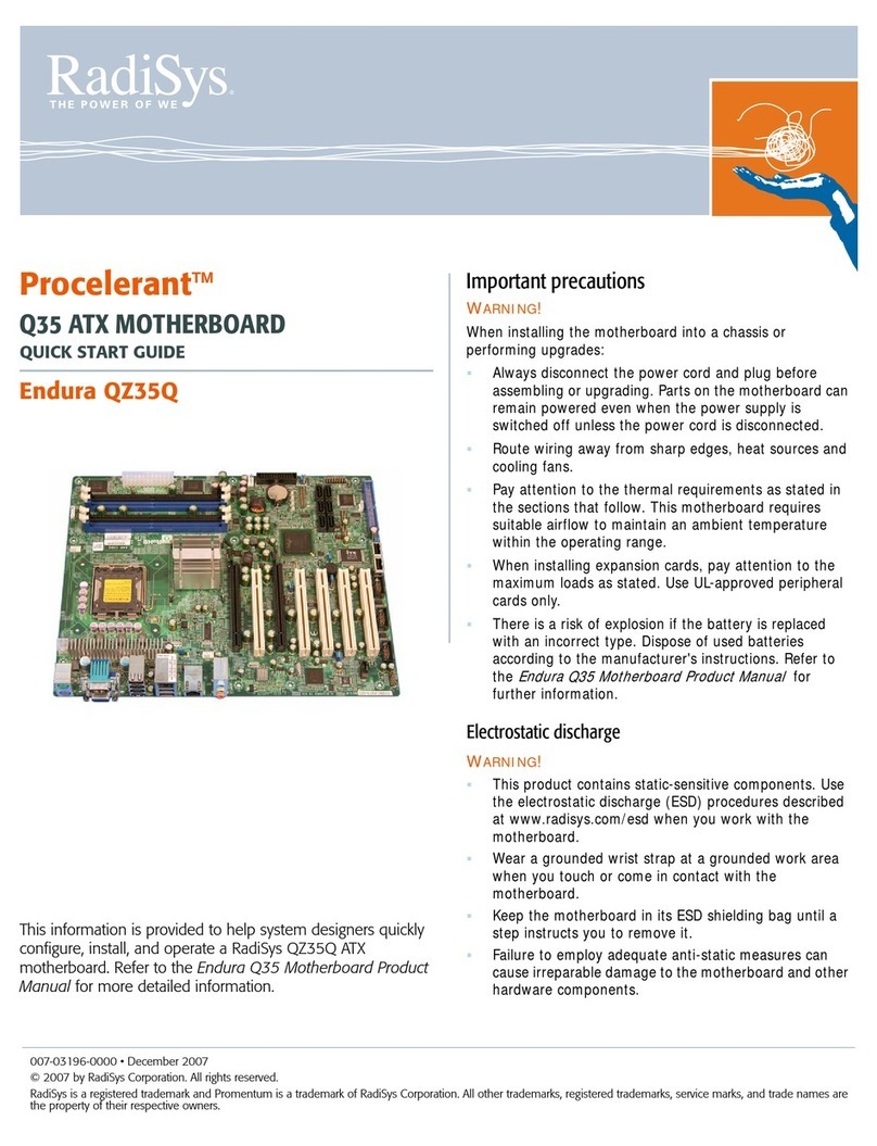
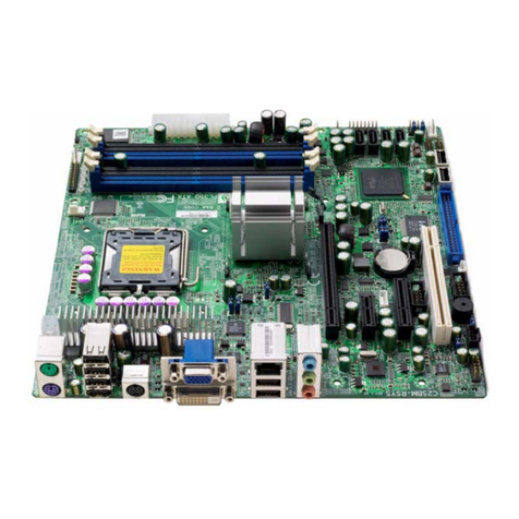
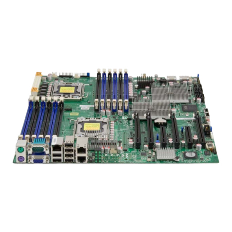
RadiSys Endura GL815E User manual

Endura
GL815E
Product Manual
www.radisys.com
World Headquarters
5445 NE Dawson Creek Drive !Hillsboro, OR 97"24 USA
Phone: 503-6"5-""00 !Fax: 503-6"5-""2"
Toll-Free: 800-950-0044
International Headquarters
Gebouw Flevopoort !Televisieweg "A
NL-"322 AC !Almere, The Netherlands
Phone: 3"36 5365595 !Fax: 3"36 5365620
97-78"2-0"
November 200"

GL815E Endura Motherboard Product Manual
Page 2 of 51
Revision History
Revision Revision History Date
".0 First Release December 2000
"."Added support for 850 MHz Celeron and ".0 GHz Pentium III
Added support for build-dependant on-board speaker
Added section on power supply selection
Added MTBF and fan drive current specifications
Updated approvals information
Added thermal specification section
Removed support for Microsoft Windows 95
Format and textual corrections
November 200"
Notational Conventions
This manual uses the following conventions:
•Screen text and syntax strings appear in this font.
•All numbers are decimal unless otherwise stated (‘h’ indicates a hexadecimal number).
•Bit 0 is the least-significant bit. If a bit is set to ", the associated description is true unless
otherwise stated.
Warnings indicate situations that may
result in physical harm to you or the
hardware.
Notes indicate important information
about the product.
Cautions indicate situations that may
result in damage to data or the
hardware.
The globe indicates a World Wide Web
address.
RadiSys is a registered trademark of RadiSys Corporation
All other trademarks, registered trademarks, service marks and trade names are the property of their
respective owners.
November 2001
Copyright © RadiSys Technology (Ireland) Ltd
All rights reserved

GL815E Endura Motherboard Product Manual
Page 3 of 51
Safety & Approvals Notices
Battery
This product contains a lithium cell.
When removing or replacing the lithium cell, do not use a conductive instrument as a short-
circuit may cause the cell to explode. Always replace the cell with one of the same type.
This product uses a CR2032 cell. Dispose of a spent cell promptly – do not recharge,
disassemble or incinerate. Keep cells away from children.
CAUTION! Danger of explosion if battery is incorrectly replaced. Replace only with the
same or equivalent type recommended by the manufacturer. Dispose of batteries according
to the manufacturer's instructions.
LAN (Local Area Network) Connector
This product may include an RJ45 LAN connector (see installation guide). Do not connect
to anything other than an Ethernet LAN.
Thermal Interface Material
This product may contain thermal interface material between devices and heatsinks. This
can cause irritation and can stain clothing. Avoid prolonged or repeated contact with the
skin and wash thoroughly with soap and water after handling. Avoid contact with eyes and
inhalation of fumes. Do not ingest.
Anti-static Precautions
This product contains static-sensitive components and should be handled with care. It is
recommended that the product be handled in a Special Handling Area (SHA) as defined in
EN"000"5-":"992. Such an area has working surfaces, floor coverings and chairs
connected to a common earth reference point. An earthed wrist strap should be worn whilst
handling. Other examples of static-sensitive devices are the memory modules and the
processor. Failure to employ adequate anti-static measures can cause irreparable damage
to components on the motherboard.
Safety
This product complies with the American Safety Standard UL"950 when installed in a suitable
chassis.
Electromagnetic Compatibility
This product complies with the following EMC standards.
FCC Class B (Title 47 of Code of Federal Regulations, parts 2 & "5, subpart B)
EN55022:"998 Class B
EN55024:"998

GL815E Endura Motherboard Product Manual
Page 4 of 51
FCC Compliance Statement
This equipment has been tested and found to comply with the limits for a Class B digital device,
pursuant to part "5 of the FCC Rules. These limits are designed to provide reasonable protection
against harmful interference in a residential installation. This equipment generates, uses and can
radiate radio frequency energy and, if not installed and used in accordance with the instructions
may cause harmful interference to radio communications. However, there is no guarantee that
interference will not occur in a particular installation. If this equipment does cause harmful
interference to radio or television reception, which can be determined by turning the equipment off
and on, the user is encouraged to try to correct the interference by one or more of the following
measures.
•Reorient or relocate the receiving antenna
•Increase the separation between the equipment and the receiver
•Connect the equipment into an outlet on a different circuit to that of the receiver
•Consult the dealer or an experienced radio/TV technician for help.
Any change or modification to this product not expressly approved by RadiSys could void the
approvals held by this product.
Legal Directives
This product complies with the relevant clauses of the following European Directives.
Low Voltage Directive 73/23/EEC
EMC Directive 89/336/EEC

GL815E Endura Motherboard Product Manual
Page 5 of 51
Contents
"Overview................................................................................................................. 7
"."Motherboard Layout...................................................................................................................8
".2 Block Diagram.........................................................................................................................."0
".3 Product Options .......................................................................................................................""
".4 Configuration............................................................................................................................"2
".4."Operation Mode Selection............................................................................................"2
".4.2 Front Panel Connections.............................................................................................."3
2 Motherboard Description ...................................................................................... "4
2."Processor ................................................................................................................................."4
2.2 System Memory ......................................................................................................................."4
2.3 Chipset ....................................................................................................................................."5
2.4 Video ........................................................................................................................................"5
2.4."System Memory Allocation..........................................................................................."5
2.4.2 Video Modes ................................................................................................................"6
2.5 Audio ........................................................................................................................................"6
2.6 Network .................................................................................................................................... "7
2.7 IDE Drives................................................................................................................................"7
2.8 Diskette Drives........................................................................................................................."7
2.9 Standard PC I/O......................................................................................................................."7
2.9."Serial Ports..................................................................................................................."8
2.9.2 Parallel Port.................................................................................................................."8
2.9.3 Infra-red Support .........................................................................................................."8
2.9.4 Keyboard and Mouse Ports.........................................................................................."8
2."0 USB Ports ................................................................................................................................"8
2."" General Purpose I/O Lines ......................................................................................................"9
2."2 CMOS RAM & RTC ................................................................................................................."9
2."3 Expansion Cards......................................................................................................................"9
2."4 System management ...............................................................................................................20
2."4."Voltage Monitoring .......................................................................................................20
2."4.2 Temperature Monitoring...............................................................................................2"
2."4.3 Fan Monitoring .............................................................................................................2"
2."4.4 Fan Control...................................................................................................................2"
2."4.5 Tamper Detection.........................................................................................................2"
2."5 Power management.................................................................................................................22
2."5."ACPI Power States ......................................................................................................22
2."5.2 ACPI Wake-up Support................................................................................................ 22
2."6 Indicators..................................................................................................................................23
2."7 BIOS.........................................................................................................................................23
2."8 Operating Systems Support.....................................................................................................23
3 Specifications........................................................................................................ 24
3."Regulatory EMC Compliance...................................................................................................24
3.2 Regulatory Safety Compliance ................................................................................................24
3.3 Environmental ..........................................................................................................................24
3.4 Thermal....................................................................................................................................25
3.5 Industry Compliance ................................................................................................................25
3.6 Miscellaneous ..........................................................................................................................25
3.7 Mechanical...............................................................................................................................26
3.7."Motherboard.................................................................................................................26
3.7.2 I/O Shield......................................................................................................................27
3.7.3 Fansink.........................................................................................................................27
3.8 Electrical...................................................................................................................................28
GL815E Endura Motherboard Product Manual
Page 6 of 51
3.8."Motherboard Power Consumption ...............................................................................28
3.8.2 Power Supply Selection ............................................................................................... 29
3.8.3 General Purpose I/O Lines...........................................................................................29
4 Motherboard BIOS................................................................................................ 30
4."Configuration............................................................................................................................30
4.2 Update and Recovery ..............................................................................................................3"
4.2."Creating a BIOS Update Diskette ................................................................................3"
4.2.2 Updating the System BIOS ..........................................................................................3"
4.2.3 Creating a BIOS Recovery Diskette............................................................................. 32
4.2.4 Recovering the System BIOS ......................................................................................32
4.2.5 Updating the Flash Bootblock ......................................................................................32
4.3 Customization ..........................................................................................................................33
4.4 BIOS Error Indications .............................................................................................................34
5 Customer Support................................................................................................. 37
Appendix A Technical Reference................................................................................... 38
A.". I/O Map ....................................................................................................................................38
A.2. PCI Interrupt Allocation ............................................................................................................39
A.3. PCI Device Assignments .........................................................................................................40
A.4. SMBus Resource Allocation ....................................................................................................40
A.5. ISA Interrupt Allocation ............................................................................................................4"
A.6. ISA DMA Channel Allocation ...................................................................................................4"
A.7. BIOS Organization ...................................................................................................................42
Appendix B Connector Descriptions .............................................................................. 43
B.". Connector Part Numbers .........................................................................................................43
B.2. AGP Expansion Slot ................................................................................................................44
B.3. PCI Expansion Slot ..................................................................................................................45
B.4. ISA Expansion Slot ..................................................................................................................46
B.5. ATX Power Supply...................................................................................................................47
B.6. Front Panel Header..................................................................................................................47
B.7. Parallel Port..............................................................................................................................47
B.8. Serial Port "............................................................................................................................. 47
B.9. Serial Port 2 .............................................................................................................................48
B."0. VGA Monitor.............................................................................................................................48
B."". Rear I/O USB Ports..................................................................................................................48
B."2. USB Channel 2 Header ...........................................................................................................48
B."3. PS/2 Keyboard .........................................................................................................................48
B."4. PS/2 Mouse..............................................................................................................................48
B."5. Keyboard Header .....................................................................................................................49
B."6. Mouse Header .........................................................................................................................49
B."7. General Purpose I/O ................................................................................................................49
B."8. IDE Drive Headers ...................................................................................................................49
B."9. Diskette Drive Header..............................................................................................................50
B.20. ATAPI CD-ROM.......................................................................................................................50
B.2". ATAPI Telephony.....................................................................................................................50
B.22. RJ45 Ethernet ..........................................................................................................................50
B.23. Processor Fan..........................................................................................................................50
B.24. System Fan..............................................................................................................................5"
B.25. LINE In and Out Jacks .............................................................................................................5"
B.26. MIC Jack ..................................................................................................................................5"
B.27. External Audio CODEC............................................................................................................5"
B.28. Flat Panel Header ....................................................................................................................5"

GL815E Endura Motherboard Product Manual
Page 7 of 51
1Overview
The GL8"5E is an ATX form factor motherboard based around an Intel Celeron or Pentium III
processor and an Intel 8"5E family chipset. It integrates video, audio, system monitoring and
Ethernet on a "2.0 x 7.5-inch board and is targeted at the embedded PC technology market.
Form Factor ATX 2.03 compliant, "2.0 x 7.5 inches
Processor 370 pin PGA socket for Intel Celeron and Pentium III processors
66, "00 or "33 MHz bus speed
Chipset Intel 8"5E with National Semiconductor PCI/ISA Bridge
Memory Two DIMM sockets for PC"00 & PC"33 SDRAM modules without ECC
or parity
Min. "6MB, max. 5"2MB memory
Video 3D graphics controller integrated within chipset
On-board PanelLink flat panel controller option
Support for DDWG DVI & VESA DFP
Audio AC97 v2."CODEC
Digital audio controller integrated within chipset
Line-in, Line-out and MIC jacks on rear panel
ATAPI CD input and telephony connectors on motherboard
Optional on-board mini-speaker
Power Management APM, ACPI, PCI PME
System Management Voltage, temperature and fan monitoring for 2 fans
Fan speed control for 2 fans
BIOS Based on PhoenixBIOS™ 4.0 release 6.0
4Mbit device
Includes POST, Setup, ACPI, APM, PnP, video BIOS
Customizable startup logo
I/O Dual rear USB "."
Third USB channel on header, fourth channel on AGP connector
Two serial ports (one on header) with IrDA in lieu of second port
Bi-directional/EPP/ECP parallel port
PS/2 keyboard and mouse (duplicated on internal headers)
General Purpose I/O Lines (8)
Network Integrated within chipset plus Intel 82562ET "0/"00Mbps Ethernet
transceiver
Disks Dual UltraDMA/"00 interfaces with ATAPI CD, LS"20 and ZIP drive
support
3-mode floppy interface with on-board connector
Expansion "AGP 4X slot
5 PCI 2.2 slots (one shared with an ISA slot)
2 ISA slots (one shared with an PCI slot)

GL815E Endura Motherboard Product Manual
Page 8 of 51
1.1 Motherboard Layout
The figure below shows the layout of the GL8"5E motherboard with the major components
identified.
17
36 37
38 39 40 41 42 43 44 45 46
31 2 45678910 12
11 13 14 15 16
18 19 20 21 22 23 24 25 26 27 2928 30 31 32 33 34 35

GL815E Endura Motherboard Product Manual
Page 9 of 51
Motherboard Component Identification
1 Clock generator 24 ATAPI telephony audio header
2 PC"00/PC"33 DIMM sockets 25 GPIO header
3 PGA370 socket for processor 26 External audio CODEC support
4 Diskette header 27 Slot 2 – PCI 2.2
5 Graphics & memory controller (GMCH) 28 Serial port 2 header
6 Secondary IDE connector 29 Firmware hub (FWH)
7 Optional Supercap 30 Slot 3 – PCI 2.2
8 3V Lithium cell – use CR2032 31 Slot 4 – PCI 2.2
9 Slot "– AGP 4X 32 Slot 5 – PCI 2.2
10 Primary IDE connector 33 Slot 6 – PCI 2.2 (shared slot)
11 Optional on-board mini-speaker 34 Slot 6 – ISA (shared slot)
12 Operating mode jumper 35 Slot 7 – ISA
13 I/O controller hub (ICH2) 36 PS/2 mouse
14 Front panel connector 37 "0/"00 Ethernet RJ45
15 System fan connector 38 PS/2 keyboard
16 ISA Bridge (NS87200) 39 USB "."channel "
17 Keyboard header 40 USB "."channel 0
18 USB "."channel 2 header 41 Serial port "
19 Mouse header 42 Parallel port
20 Power supply connector 43 VGA monitor
21 Processor fan power connector 44 Stereo audio line output jack
22 Digital flat panel header 45 Stereo audio line input jack
23 ATAPI CD-ROM audio header 46 Mono microphone input jack

GL815E Endura Motherboard Product Manual
Page 10 of 51
1.2 Block Diagram
The figure below shows a block diagram of the GL8"5E motherboard.
Intel Celeron or
Pentium III Processor
PGA370
Graphics & Memory
Controller
(GMCH)
I/O Controller Hub
(ICH2)
ISA Bridge
(NS87200)
Super I/O
(PC87366 LPC)
DIMM 0
Slot 1, AGP 1/2/4X
Slots 2 to 6, PCI 2.2
Slots 6 to 7, ISA
DIMM 1
Clocks
PanelLink
Controller
Firmware Hub
(FWH)
Flat Panel
Header
VGA
Connector
VRM
AC97
Audio CODEC
USB0 Connector
Lithium cell or
optional SuperCap
Intel 82562ET
LAN PHY
RJ45
Serial Port 1
Connector
Primary IDE
Connector
Secondary IDE
Connector
Diskette Drive
Connector
Serial Port 2
Header
Parallel Port
Connector
PS/2 Keyboard
Connector
Header
Header
PS/2 Mouse
Connector
Internal Digital I/O
Header
Line-in Jack
Line-out Jack
Microphone JackCD-ROM Line-in
Telephony
External CODEC
Mini-speaker
Amp
USB1 Connector
USB2 Header
Hub Link USB Channel 3
1/2/4X AGP Bus
SDRAM Bus
(100/133 MHz)
PCI Bus
(33 MHz)
LPC Bus
(33 MHz)
Fan Control
Voltage Monitoring
Fan Monitoring

GL815E Endura Motherboard Product Manual
Page 11 of 51
1.3 Product Options
The table below lists the product options available.
Functions GL815E-V GL815E-L GL815E-FPL
Audio Yes Yes Yes
Flat panel interface No No Yes
Flat panel rear
connector"No No No
LAN No Yes Yes
On-board speaker No No No
SuperCap No No No
Each of the products is available with a choice of CPU speed. Consult the latest price list for the
available options. Other product options are available to special order for high volume customers.
1The flat panel rear connector assembly is available as an accessory.

GL815E Endura Motherboard Product Manual
Page 12 of 51
Operating mode
Normal
Configure
Recover
1.4 Configuration
The majority of the configuration of the motherboard is done
through the Setup utility built into the BIOS – discussed later
in this document. There is, however, one jumper that controls
the operation of the motherboard as described below.
1.4.1 Operation Mode Selection
This jumper selects one of three operating modes for the motherboard – Normal, Configure and
Recovery modes. The factory default position for this jumper selects ‘Normal’ mode.
Normal Mode
This is the position the jumper should be in for normal operation of the motherboard. If the
motherboard detects corruption in the BIOS ROM, then recovery mode will be entered regardless of
the state of the jumper.
Recovery Mode
If the jumper is in the recovery mode position or if the motherboard detects a corrupted BIOS ROM
then recovery mode is entered. The motherboard will not boot and will wait until a valid recovery
diskette is detected and will then copy a new BIOS into the ROM. The motherboard must be
powered down and then re-powered with the jumper in the normal position before normal operation
can resume.
Configure Mode
With the jumper in this position the motherboard will automatically run the BIOS Setup utility
regardless of the state of the Setup disable flag that can be set in the BIOS defaults. Additional
BIOS settings are also available within Setup in this mode.

GL815E Endura Motherboard Product Manual
Page 13 of 51
1.4.2 Front Panel Connections
The primary controls and indicators for the motherboard are connected via the front panel connector
using either a single ribbon cable to a 'front panel' assembly, or using a number of small PC-
standard connectors. The functions are described below. See appendix B for the connector pin-out
information.
Power LED
This can be used to connect either a single-color LED (usually green) or a two-terminal bi-color LED
(usually green/yellow) to indicate the powered status of the motherboard. In both cases, the 'green'
anode should be attached to pin 2 of the front panel connector. See the Indicators section later in
this document for further information.
Power Switch
A momentary switch should be connected between pins 6 and 8 of the power connector if the
motherboard is used with a soft-switch power supply. If the switch is closed for greater than
approximately 4 seconds, the motherboard will power off immediately, regardless of the state of the
operating system, losing any system context information. This switch is redundant when using a
hard-switch power supply.
Reset Switch
If used, a momentary switch connected between pins 5 and 7 will cause the motherboard to restart
when closed.
Hard Disk LED
A single color LED should be connected between pins "(anode) and 3 to indicate hard disk activity
on either of the two ATA channels.
Speaker
Connect an external speaker between pins "0 and "" or "0 and "6. This is used only for the PC
'beep' functions - it cannot be used as an output of the audio CODEC. The speaker should typically
be 8#.
Tamper Switch
Connect a momentary switch between pins "8 and 20 to make use of the tamper detection logic of
the motherboard. The switch should be open when the chassis is closed.
Infra-red port
Pins 9, "", "3 and "5 provide an interface to an infra-red receiver/transmitter module. Pins 9 and "3
provide the +5V module power and signal ground return.

GL815E Endura Motherboard Product Manual
Page 14 of 51
2Motherboard Description
2.1 Processor
The GL8"5E motherboard supports Intel Celeron and Pentium III processors in a PGA370 package
(FC-PGA). The table below lists the supported processors. An on-board voltage regulator generates
the voltage for the CPU. Both the processor voltage and the operating frequency are automatically
adjusted by the motherboard to suit the installed processor.
Processor Type Processor Speed CPU bus speed Cache size Package
Intel Celeron 566 MHz 66 MHz "28kB FC-PGA
Intel Celeron 733 MHz 66 MHz "28kB FC-PGA
Intel Celeron 850 MHz "00 MHz "28kB FC-PGA
Intel Pentium III 600 MHz "00 MHz 256kB FC-PGA
Intel Pentium III 700 MHz "00 MHz 256kB FC-PGA
Intel Pentium III 733 MHz "33 MHz 256kB FC-PGA
Intel Pentium III 850 MHz "00 MHz 256kB FC-PGA
Intel Pentium III 866 MHz "33 MHz 256kB FC-PGA
Intel Pentium III ".0 GHz "33 MHz 256kB FC-PGA
2.2 System Memory
The GL8"5E motherboard has two DIMM sockets to accept PC"00 or PC"33 modules. The product
does not accept PC66 modules. The sockets may be populated in any order and each can accept
either single or double-sided modules. The minimum total memory size is "6MB and the maximum
is 5"2MB. The BIOS automatically configures the motherboard for the correct size, speed and type.
For best performance, use PC"33 modules with a "33MHz bus processor. When using a "00MHz
bus processor, the module will always operate at "00MHz regardless of type. See the Manuals,
Drivers & BIOS section on the RadiSys web site at www.radisys.com for a list of memory modules
that have been tested with this product.
When using the on-board video controller, the frame buffer is held within system memory
and thus less memory is available to the operating system.
Each memory module should meet the following requirements
•Compliance with the Intel PC"00 or PC"33 specification
•Inclusion of a serial presence detect (SPD) ROM
•The module type is 3.3V "68-pin unbuffered synchronous DRAM (SDRAM)
•Based on "6Mb, 64Mb, "28Mb or 256Mb devices
•Capacity of between "6MB and 5"2MB
•64 bits wide. ECC or parity is not supported

GL815E Endura Motherboard Product Manual
Page 15 of 51
2.3 Chipset
The GL8"5E motherboard is based around an Intel 8"5E chipset comprising two parts -
•Graphics and memory controller hub (GMCH). This includes the processor interface, a high-
performance 3D graphics controller and the system memory controller.
•I/O controller hub (ICH2). This provides all the PCAT-compatible devices and the PCI bus
interface. In addition, it integrates Ethernet, USB and SMBus controllers, a dual UltraATA/"00
disk controller, an AC97 digital audio controller and power management functions.
In addition, a National Semiconductor NS87200 ISA bridge is used to support ISA devices and a
firmware hub flash ROM contains the system BIOS, setup utility and video BIOS.
2.4 Video
The video controller is integrated within the 8"5E chipset GMCH and provides the features listed
below.
•2D graphics with full 2D acceleration
•3D graphics with extensive rendering capabilities
•Hardware motion compensation for software MPEG2 decode
•System memory is used as frame buffer storage
•"5-way D-type for analog RGB output with VESA DDC2B capability
•Optional on-board Silicon Image SII"64 PanelLink flat panel video controller
•Optional Vesa DFP or DDWG DVI connector on rear panel
The motherboard has two output connectors – a standard analog VGA connector and a header for
the optional digital flat panel controller. A Vesa DFP or a DDWG DVI connector on the rear panel is
available as an option. Whilst it is possible to connect a monitor to both the VGA and flat panel
connectors at the same time, the displays will be identical since there is only one video controller.
The BIOS supports multiple independent displays via PCI (or ISA) video cards.
2.4.1 System Memory Allocation
The video controller does not have dedicated frame buffer memory but instead makes use of
system memory for all its needs. This must be taken into account when the amount of system
memory is chosen. When the on-board video controller is not used, it should be disabled completely
via BIOS Setup to prevent system memory being allocated to the controller.
The motherboard BIOS allocates "MB of system memory to the video controller to support legacy
VGA graphics. The amount of system memory reported by the BIOS will reflect this reduction when
the on-board video controller is enabled. Once the operating system loads, the video drivers
allocate further system memory dependant on availability as described in the table below for Intel
PV 4.x video drivers. Systems using Windows NT 4.0, Windows 2000 or those that require "6M
colors at a resolution greater than "024 x 768 must have at least 64MB of system memory.
Total Allocation of System Memory for On-board Video (including 1MB legacy support)
Total System Memory Size
Operating System 32MB 64MB 128MB or greater
Windows 98 7MB ""MB ""MB
Windows NT 4.0 Not valid "0MB "0MB
Windows 2000 Not valid "0MB ""MB

GL815E Endura Motherboard Product Manual
Page 16 of 51
2.4.2 Video Modes
The Intel 8"5E chipset supports a wide variety of video modes. The drivers for specific operating
systems support a subset of these modes. The table below lists the video modes supported by the
Windows and Linux drivers.
Resolution Color Depth
(bpp) **
Windows 2D
Refresh Rates
(Hz)
Windows 3D
Refresh Rates
(Hz)
Linux 2D
Refresh
Rates (Hz)
Flat Panel
Refresh
Rates (Hz)
4 60, 70, 72, 75, 85
8, 24 60, 70, 72, 75, 85 60, 75, 85 60 *
640 x 480
"6 60, 70, 72, 75, 85 60, 70, 72, 75, 85 60, 75, 85 60 *
8, 24 75, 85 60 *720 x 480
"6 75, 85 75, 85 60 *
8, 24 60, 75, 85 60 *720 x 576
"6 60, 75, 85 75, 85 60 *
8, 24 60, 70, 72, 75, 85 60, 75, 85 60 *800 x 600
"6 60, 70, 72, 75, 85 60, 70, 72, 75, 85 60, 75, 85 60 *
8, 24 60, 70, 72, 75, 85 60, 75, 85 60"024 x 768
"6 60, 70, 72, 75, 85 60, 70, 75, 85 60, 75, 85 60
""52 x 864 8, "6, 24 60, 70, 72, 75, 85 60, 75, 85
"280 x 960 8, "6 60, 75, 85
8, "6 60, 70, 72, 75, 85 60, 75, 85"280 x "024
24 60, 70, 75, 85 60, 75, 85
8 60, 70, 72, 75, 85 60, 75, 85"600 x "200
"6 60, 75, 85
* These resolutions are supported via centering.
** Bits per pixel. 4bpp="6 colors, 8bpp=256 colors, "6bpp=64k colors, 24bpp="6M colors.
2.5 Audio
The chipset ICH2 contains a digital audio controller that is supported on the motherboard by an
Analog Devices AD"885 audio CODEC. The motherboard has an on-board ATAPI CD-ROM stereo
audio line-input connector and a mono ATAPI telephony connector. The rear panel has three
3.5mm audio jacks for stereo Line output (driven by an amplifier and suitable for driving
headphones), stereo Line input and a monaural microphone input with phantom power suitable for
electret microphones.
An optional mini-speaker can be fitted to provide PC speaker functions (error 'beep' etc.).

GL815E Endura Motherboard Product Manual
Page 17 of 51
2.6 Network
The GL8"5E supports an optional "0/"00 Ethernet controller based around the controller integrated
within the chipset and an Intel GD82562ET transceiver. An RJ45 connector located on the rear
panel integrates two LED indicators to provide link status information. The list below describes the
features provided.
•IEEE 802.3 "0Base-T and "00Base-TX compatible
•32-bit bus-mastering PCI device
•Jumper-less configuration
•RJ45 with two integral LEDs showing line activity, link integrity and line speed
The operation of the two indicators is described in the table below.
LED color LED state Indicates
Off "0Mbps link speedGreen
On "00Mbps link speed
Off No link is established
Steady on Link is established but there is no communication activity
Yellow
Blinking Link is established and communication activity is detected
2.7 IDE Drives
Two independent bus-mastering IDE interfaces are provided, each supporting ATA modes up to
UltraATA/"00. The following drive types are supported.
•ATA hard disks up to UltraATA/"00 speeds
•ATAPI devices such as CD-ROMs
•LS"20 drives
The BIOS supports logical block addressing (LBA) and extended CHS translation modes for hard
disks. When booting from LS"20 drives, the correct mode (floppy or hard disk) must be chosen in
Setup. The BIOS supports both automatic and manual determination of ATA cable type (80 - or 40-
pin) to support UltraATA/66 or ATA/"00 drives.
2.8 Diskette Drives
The diskette drive interface supports a maximum of two drives. The drives should be 2- or 3-mode
3.5-inch devices supporting 720kB, ".2MB or ".44MB formats. The controller is located at I/O
addresses 3F0-3F7h and uses IRQ6.
2.9 Standard PC I/O
The standard PC I/O functions serial ports, parallel ports, keyboard and mouse ports and diskette
drive controller are provided via a National Semiconductor PC87366 Super I/O (SIO) device
attached to the low pin count (LPC) bus from the chipset ICH2. In addition, this device provides
system monitoring and fan control functions and general-purpose I/O lines.

GL815E Endura Motherboard Product Manual
Page 18 of 51
2.9.1 Serial Ports
The GL8"5E motherboard supports two "6C550-compatible serial ports that can operate at speeds
of up to ""5.2kbps. Serial port "is located on the rear panel whilst serial port 2 is via a header.
Each port can be assigned as COM"through COM4 via the BIOS Setup utility:-
•I/O address 3F8-3FFh, IRQ4
•I/O address 2F8-2FFh, IRQ3
•I/O address 3E8-3EFh, IRQ4
•I/O address 2E8-2EFh, IRQ3
2.9.2 Parallel Port
The GL8"5E has a 25 way female D-sub parallel port connector located on the rear panel. It
supports the following operating modes, configured via the BIOS Setup utility.
•Standard PC-compatible parallel port
•Bi-directional parallel port
•EPP mode
•ECP mode
The I/O locations can be assigned as follows.
•I/O address 378-37Fh & 778-77Fh, IRQ5 or IRQ7
•I/O address 278-27Fh & 678-67Fh, IRQ5 or IRQ7
2.9.3 Infra-red Support
The GL8"5E motherboard supports an IrDA compliant infra-red interface via the front panel header.
An IR transceiver must be added such as the Hewlett Packard HSDL-320"or the HSDL-36"0
device. The IR port shares the serial port 2 channel and thus the two ports cannot be used
simultaneously. A transfer rate of up to ""5kbps is supported.
2.9.4 Keyboard and Mouse Ports
Two PS/2 style keyboard and mouse ports are provided on the rear panel. The two ports are
interchangeable with the motherboard automatically detecting which peripheral is attached to which
port. Both ports provide a resettable fuse protected +5V supply to the peripheral. In addition, both
the keyboard and mouse ports are accessible internally via 4-way headers.
The keyboard controller is functionally equivalent to the 8042 standard and is located at I/O
addresses 60-64h and uses IRQ". The mouse shares the same controller and uses IRQ"2. The
keyboard controller code is Phoenix version 42i.
2.10 USB Ports
GL8"5E supports four independent USB "."compliant ports via the 2 USB controllers (each with 2
channels) contained within the chipset ICH2. Two channels are provided on the rear panel, a third is
available internally on a 5-way ATAPI-style header and a fourth via the AGP connector. The first
three ports all provide a resettable fuse protected +5V supply to the peripheral. The AGP USB
channel power is provided via the AGP connector and it is the responsibility of the AGP adapter to
protect this supply if required. The table below summarizes the USB channel allocation.

GL815E Endura Motherboard Product Manual
Page 19 of 51
USB channel Connector location Controller
Channel 0 Rear I/O (bottom) Controller "
Channel "Rear I/O (top) Controller "
Channel 2 Header Controller 2
Channel 3 AGP slot Controller 2
The BIOS supports the use of a USB keyboard and/or mouse in lieu of a PS/2 device via the BIOS
customization tools (the feature is disabled by default). This USB legacy support provides emulation
of standard keyboards and/or mice and since it causes performance degradation should be enabled
only when the operating system being used also supports USB (the emulation is automatically
disabled once the operating system is running).
2.11 General Purpose I/O Lines
In order to support products that require a small number of internal input or output lines (such as
switches or LED indicators), the GL8"5E provides access to 8 general-purpose lines via a "2-pin
header. Each line can be programmed independently as an input or an output. The signals are
provided by the National Semiconductor PC87366 Super I/O device GPIO port 2. It is the
responsibility of the customer to provide suitable software to control these lines.
2.12 CMOS RAM & RTC
The chipset integrates a Motorola MC"468"8A compatible real-time clock (RTC) and 256 bytes of
CMOS RAM that is used by the BIOS to store configuration information. A replaceable primary
lithium coin cell or, optionally, a Super Cap backs up both the RTC and the CMOS RAM. The
former provides for approximately 5 years of unpowered backup. The SuperCap provides for at
least "-hour life and eliminates cell replacement as a reason for scheduled maintenance.
The lithium coin cell is a CR2032 device.
The RTC includes a century byte and is supported by the BIOS to provide year 2000 compliance.
When the +5V standby power is applied to the motherboard, the RTC and the CMOS RAM are
powered from that rather than the lithium cell or the optional SuperCap.
2.13 Expansion Cards
The motherboard provides 7 expansion card slots, one of which supports either an ISA or a PCI
adapter.
AGP Slot
The motherboard provides a single universal AGP slot, supporting "X, 2X and 4X adapter cards
and automatically switches the interface appropriate to the adapter. Since there is no physical
keying on the universal AGP connector, always ensure that the adapter is fitted correctly before
applying power. The AGP card retention mechanism is supported. An independent USB "."
compliant port is provided on the AGP interface.
PCI Slots
The motherboard provides 5 bus-master PCI 2.2 compliant slots, one of which is shared with an ISA
slot. The motherboard generates the 3.3Vaux supply to these slots using the 5V standby input from
the power supply. Always ensure that the 5V standby rail can support the required current when
using a PCI card that makes use of the 3.3Vaux supply.

GL815E Endura Motherboard Product Manual
Page 20 of 51
ISA Slots
The motherboard provides 2 ISA slots, one of which is shared with a PCI slot. The National
Semiconductor NS87200 provides the PCI to ISA bridge. In order to fully support the ISA bus power
rails, the ATX power supply should provide –5V. Since the motherboard makes no use of this rail, it
need not be provided if the ISA adapters do not require it.
Support for ISA card option ROMs is possible only if certain BIOS features are disabled –
see the BIOS section for details.
2.14 System management
The GL8"5E motherboard includes hardware system management functions integrated into the
National Semiconductor PC87366 Super I/O (SIO) device. They monitor system voltages,
motherboard and CPU temperatures, fan speed and control system fans. The following sections
describe this in more detail. The BIOS Setup utility can be used to display the status of the system
monitors.
2.14.1 Voltage Monitoring
The table below details the motherboard voltage rails monitored and their usage.
Voltage Rail Usage on Motherboard
+"2V Serial ports, processor voltage generation, audio quiet supply, fans.
+5.0V Processor voltage generation, internal logic, keyboard, mouse, USB and
video ports.
+3.3V Chipset ICH2, firmware hub, ISA bridge, audio CODEC, SIO, clock
generator, flat panel controller.
+2.5V Clock generator.
+".8V Chipset GMCH, chipset ICH2.
+".5V Processor bus termination, processor signaling.
-"2V Serial ports.
VCPU Processor core voltage.
+3.3V Standby Primary standby voltage to systems that control motherboard wake-up,
System memory DIMMs, Ethernet controller.
VBAT* This rail is used to power the RTC and the CMOS RAM.
* The VBAT supply is generated from the +3.3V standby supply when available in order to preserve
the life of the lithium cell. This means, however, that the voltage read via the monitor is that of the
standby rail and not of the lithium cell itself.
A regulator on the motherboard generates the processor operating voltage with each processor
selecting the correct voltage automatically. The table below indicates the correct operating voltage
for the different processors.
Table of contents
Other RadiSys Motherboard manuals

RadiSys
RadiSys BG845G User manual

RadiSys
RadiSys EPC-3208 Series User manual

RadiSys
RadiSys ENDURA TP945GM User manual

RadiSys
RadiSys P3000BX2 Series Reference guide

RadiSys
RadiSys Endura QZ35Q User manual

RadiSys
RadiSys PROCELERANT SB5520DT1-SATA User manual

RadiSys
RadiSys PL35Q User manual

RadiSys
RadiSys KP915GV User manual
Popular Motherboard manuals by other brands

Intel
Intel 815EG Design guide

Texas Instruments
Texas Instruments TPS92520-Q1 user guide

Texas Instruments
Texas Instruments MSP-EXP430FR5739 user guide

P&E Microcomputer Systems
P&E Microcomputer Systems XPC560S EVB user manual

EPOX
EPOX 3WXM4 instructions

Autek
Autek Ikey 820 Instruction for Update and Activate