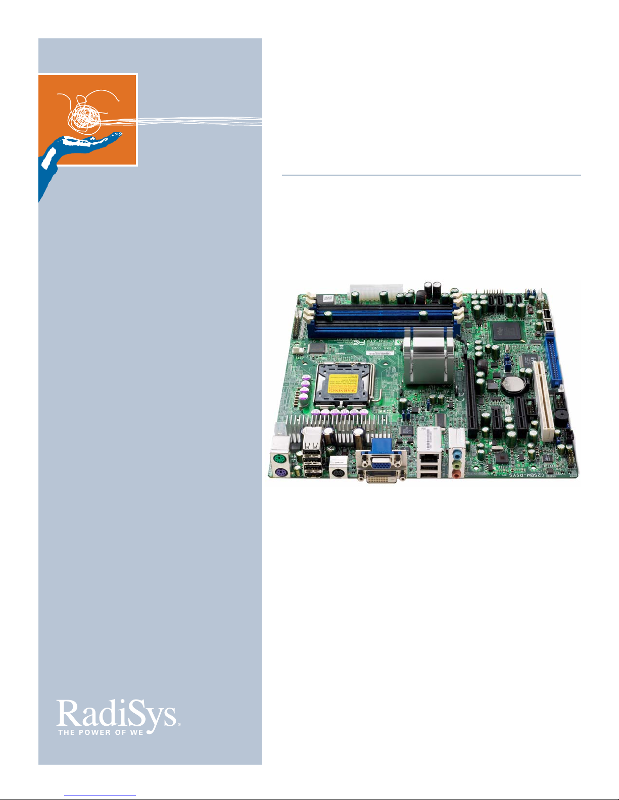
RadiSys PL35Q User manual

www.radisys.com
PROCELERANT™
ENDURA Q35 MOTHERBOARD
PRODUCT MANUAL
007-03198-0000 • December 2007
PL35Q

Release history
Release Date Description
-0000 December 2007 First release.
Copyright © 2007 by RadiSys Corporation. All rights reserved.
Portions of this manual are copyrighted by the PCI Industrial Computer Manufacturers Group, and are reprinted with permission.
RadiSys is a registered trademark and Procelerant is a trademark of RadiSys Corporation. Intel and Celeron are registered trademarks and
Intel Core is a trademark of Intel Corporation. Microsoft, Windows, and Windows XP are registered trademarks of Microsoft Corporation.
Red Hat and Red Hat Linux are registered trademarks of Red Hat, Inc. Linux is a registered trademark of Linus Torvalds. Phoenix is a
registered trademark and TrustedCore is a trademark of Phoenix Technologies.
All other trademarks, registered trademarks, service marks, and trade names are the property of their respective owners.

3
About this manual .......................................................................................................................................... 7
Safety notices................................................................................................................................................... 7
Electrostatic discharge ........................................................................................................................................... 7
Lithium cell battery................................................................................................................................................. 7
Where to get more product information................................................................................................... 7
Chapter 1: Product Overview............................................................................... 9
Product codes.................................................................................................................................................. 9
Board layout..................................................................................................................................................... 9
Chapter 2: Product Specification ......................................................................... 11
Mechanical specifications.............................................................................................................................. 11
Motherboard ........................................................................................................................................................... 11
I/O shield.................................................................................................................................................................. 12
Thermal specifications ................................................................................................................................... 12
Electrical specifications................................................................................................................................... 12
Motherboard power consumption..................................................................................................................... 12
Power delivery to expansion slots ...................................................................................................................... 16
Power budget.......................................................................................................................................................... 17
Environmental specifications........................................................................................................................ 17
Compliance ...................................................................................................................................................... 18
EMC compliance..................................................................................................................................................... 18
Safety compliance .................................................................................................................................................. 18
Environmental compliance .................................................................................................................................. 18
Industry compliance .............................................................................................................................................. 18
MTBF reliability predictions .......................................................................................................................... 19
Chapter 3: Hardware Reference .......................................................................... 21
General specifications.................................................................................................................................... 21
Block diagram.................................................................................................................................................. 23
Power supply ................................................................................................................................................... 24
Voltage requirements............................................................................................................................................ 24
Processor........................................................................................................................................................... 25
Voltage requirements............................................................................................................................................ 25
Thermal requirements........................................................................................................................................... 25
Memory............................................................................................................................................................. 26
TABLE OF CONTENTS

4
Chipset............................................................................................................................................................... 26
Graphics and Memory Controller Hub.............................................................................................................. 26
I/O Controller Hub ................................................................................................................................................. 27
Video.................................................................................................................................................................. 28
System memory allocation................................................................................................................................... 28
PCI Express graphics .............................................................................................................................................. 28
VGA............................................................................................................................................................................ 29
Dual DVI MEC ......................................................................................................................................................... 29
DVI-D......................................................................................................................................................................... 29
S-Video...................................................................................................................................................................... 29
Audio ................................................................................................................................................................. 30
Network............................................................................................................................................................. 30
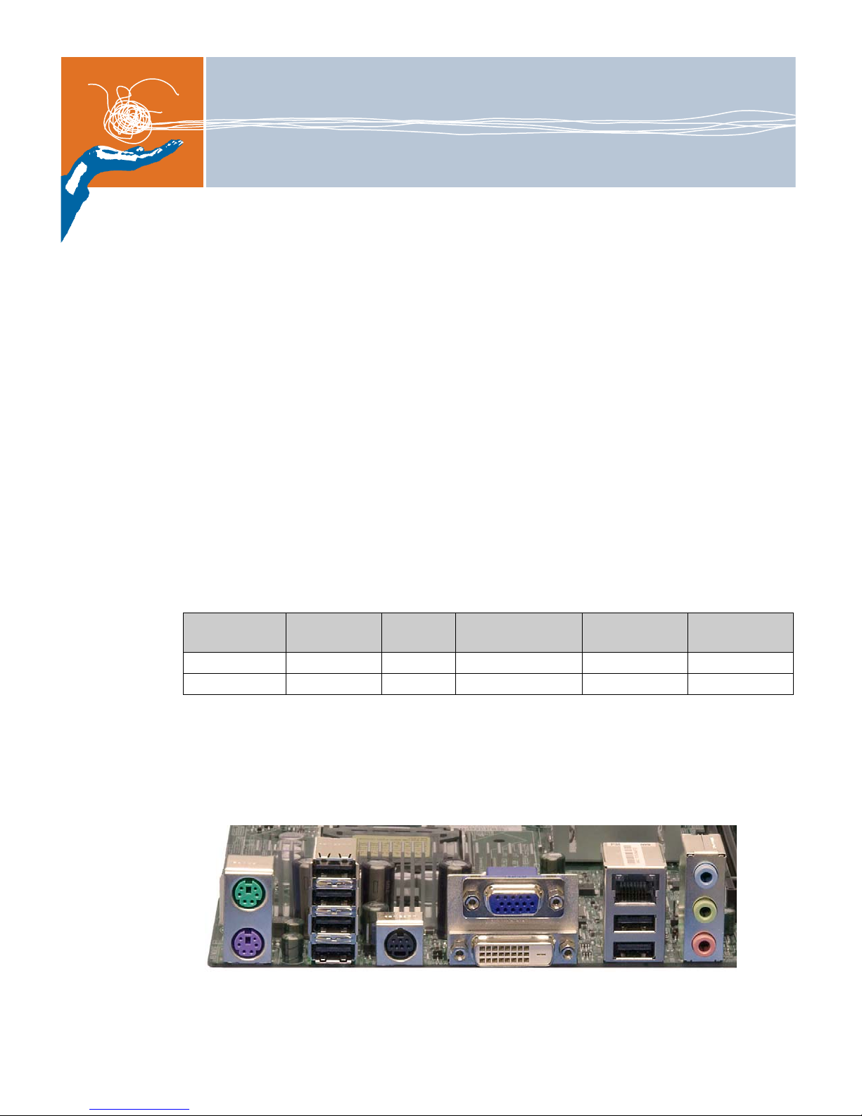
I/O ...................................................................................................................................................................... 31
SATA .......................................................................................................................................................................... 31
UART.......................................................................................................................................................................... 31
USB............................................................................................................................................................................ 31
PS/2 mouse and keyboard................................................................................................................................... 32
Super I/O.................................................................................................................................................................. 32
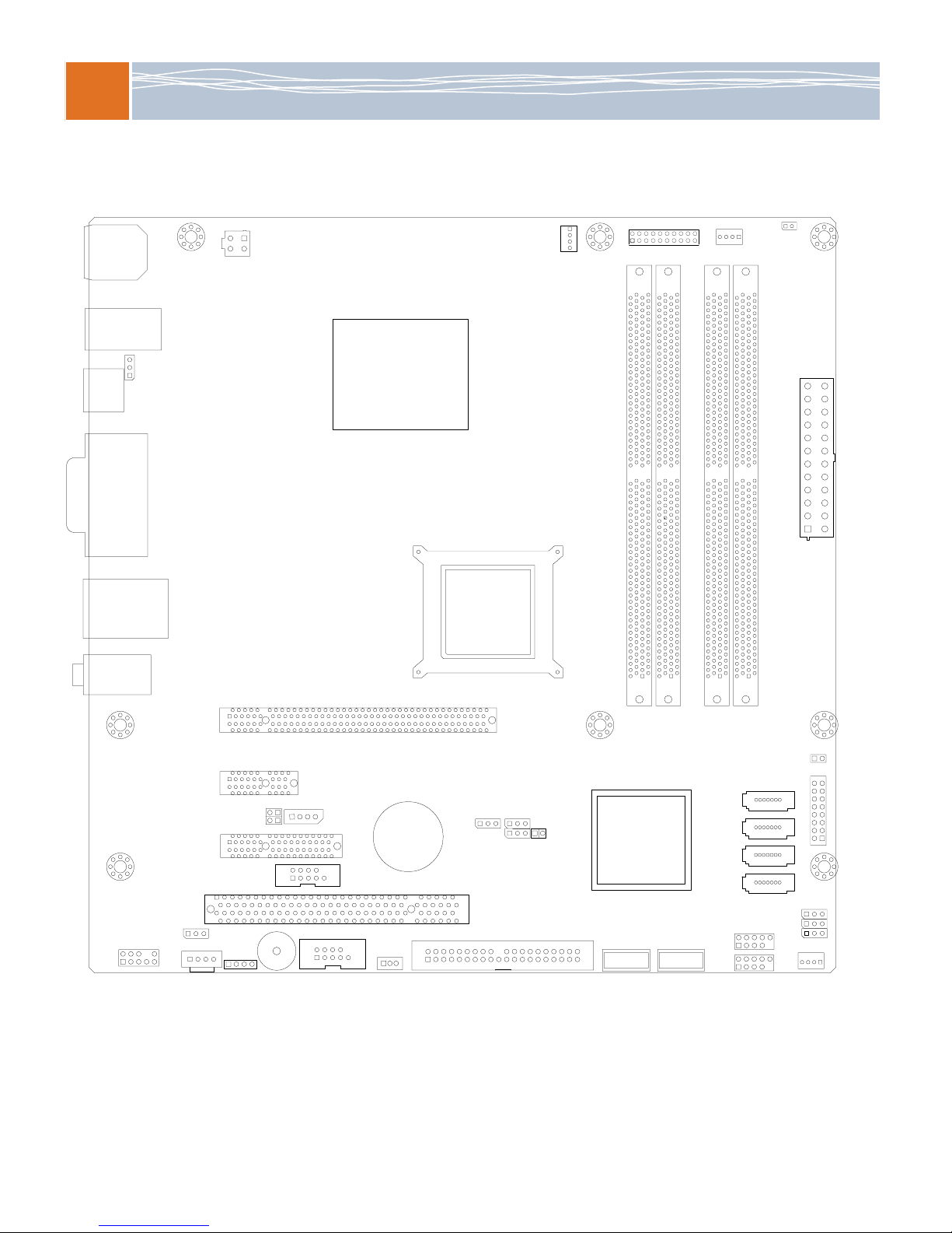
Expansion interfaces....................................................................................................................................... 32
IDE ............................................................................................................................................................................. 32
PCI.............................................................................................................................................................................. 32
PCI Express............................................................................................................................................................... 32
CMOS RAM and RTC ..................................................................................................................................... 33
Firmware hub (FWH)..................................................................................................................................... 33
Power management....................................................................................................................................... 34
ACPI power states................................................................................................................................................... 34
ACPI wake-up .......................................................................................................................................................... 34
System management ..................................................................................................................................... 35
Voltage monitoring ................................................................................................................................................ 35
Temperature monitoring ...................................................................................................................................... 35
Fan control............................................................................................................................................................... 36
Front panel connections and indicators..................................................................................................... 36
Power switch............................................................................................................................................................ 36
Reset switch ............................................................................................................................................................. 36
Power LED................................................................................................................................................................ 36
Hard disk LED.......................................................................................................................................................... 37
Overheat/fan failure LED...................................................................................................................................... 37
LAN activity LED...................................................................................................................................................... 37
Chapter 4: BIOS Configuration and OS Support .............................................. 39
BIOS overview ................................................................................................................................................. 39
POST and boot process................................................................................................................................. 39
BIOS setup........................................................................................................................................................ 40
Update and recovery...................................................................................................................................... 40
BIOS customization........................................................................................................................................ 40
Operating system support ............................................................................................................................ 40
Drivers and utilities......................................................................................................................................... 40

5
Appendix A: Connector Description................................................................... 41
Onboard connector part numbers.............................................................................................................. 41
Jumper settings ............................................................................................................................................... 42
Speaker (J9)............................................................................................................................................................. 42
CMOS clear (JRTC1) .............................................................................................................................................. 42
PCI slots to system management bus speeds (JI2C1)................................................................................... 42
PCI Express slots to system management bus speeds (JI2C2).................................................................... 43
Watch dog (JWD)................................................................................................................................................... 43
Audio (JP5) .............................................................................................................................................................. 44
Gigabit LAN (JPL1, JPL2) ...................................................................................................................................... 44
ITE IDE (JP2)............................................................................................................................................................ 44
Internal device connectors............................................................................................................................ 45
ATX power connector (24-pin, 12V)) ............................................................................................................... 45
ATX power connector (4-pin, 12V)..................................................................................................................... 45
CD-ROM header..................................................................................................................................................... 45
Clear CMOS jumper............................................................................................................................................... 46
Fan header............................................................................................................................................................... 46
Front panel I/O header ......................................................................................................................................... 46
IDE connector.......................................................................................................................................................... 47
PCI Express x1 slot.................................................................................................................................................. 48
PCI Express x4 slot.................................................................................................................................................. 49
PCI Express x16 slot ............................................................................................................................................... 50
PCI slot...................................................................................................................................................................... 53
SATA header.......................................................... 55
SMBus header......................................................................................................................................................... 55
UART port (internal) .............................................................................................................................................. 55
USB header (internal) ........................................................................................................................................... 55
External Device Connectors.......................................................................................................................... 56
Audio jacks (triple, build option) ........................................................................................................................ 56
PS/2 mouse and keyboard................................................................................................................................... 56
.................................................................................................................................................................................... 56
RJ45 Gigabit Ethernet port ................................................................................................................................... 56
USB ports (rear I/O) .............................................................................................................................................. 56
VGA connector........................................................................................................................................................ 57
Appendix B: System resources............................................................................ 59
I/O map............................................................................................................................................................. 59
PCI bus topology............................................................................................................................................. 60
SMBus resource allocation ........................................................................................................................... 61
ISA interrupt allocation .................................................................................................................................. 61
ISA DMA channel allocation......................................................................................................................... 62
POST checkpoint codes................................................................................................................................. 63
POST 80 codes........................................................................................................................................................ 63
Error message codes ............................................................................................................................................. 69
Appendix C: Industry Standard References....................................................... 71

6

7
PREFACE
About this manual
This manual is written for engineers and technicians who will integrate the Procelerant™ Endura
Q35 motherboards into their own products. For instructions on setting up an Endura Q35
motherboard, refer to the Procelerant Endura Q35 Motherboard Quick Start Guide available on
the RadiSys® Web site, www.radisys.com.
Safety notices
Electrostatic discharge
WARNING! This product contains static-sensitive components and should be handled with care.
Failure to employ adequate anti-static measures can cause irreparable damage to components.
To avoid electrostatic discharge (ESD) damage, the following precautions are strongly
recommended.
Keep each module/PCB in its ESD shielding bag until you are ready to install it.
Before touching a module, attach an ESD wrist strap to your wrist and connect its other end
to a known ground.
Handle the module only in an area that has its working surfaces, floor coverings, and chairs
connected to a known ground.
Hold modules only by their edges and mounting hardware. Avoid touching PCB
components and connector pins.
For further information on ESD, visit www.esda.org.
Lithium cell battery
WARNING!
When replacing the battery on the motherboard, use only lithium cell battery type CR2032.
Using any other battery may damage the board.
Do not use a conductive instrument to remove the battery.
Dispose of the spent battery promptly. Do not recharge, disassemble, or incinerate the battery.
Keep the battery away from children.
Where to get more product information
For additional product information, visit the motherboard product pages on the RadiSys Web site
at www.radisys.com for access to datasheets, product documentation, BIOS releases, and
drivers.

8

9
1
PRODUCT OVERVIEW
The Procelerant Endura Q35 ATX and microATX motherboards are designed for use in a variety
of commercial products, such as medical imaging, gaming, test and measurement, industrial
automation, and transaction terminals. All Endura Q35 motherboard models are RoHS
compliant and Energy Star compliant.
Major features of the Q35 microATX motherboard include:
Integrated Intel Graphics Memory Accelerator (GMA) 3100 graphics controller
PCI Express x16 graphics slot that can support PCI Express graphics acceleration cards
Integrated DVI-D for flat panel displays
Integrated S-Video port
PCI Express x4 slot for high-bandwidth data-capture devices
Single Gigabit Ethernet for high-bandwidth data communications
Media expansion card support (model PLV03-0-0 only)
Product codes
Note: Processors and memory modules are not included with product codes ending in -0-0.
Board layout
Figure 1. PL35Q board layout: rear I/O panel
Table 1. Endura Q35 product codes
Product code ICH chipset Gigabit
Ethernet Onboard video GPIO and
watchdog timer I/O shield
PLV03-0-0 ICH9 1 VGA No IOSHLD-PL
PLVDS03-0-0 ICH9 1 VGA, S-Video, DVI No IOSHLD-PL
PS/2 S-Video
Mouse
Line Out
Line In
Keyboard Microphone
In
VGA
DVI
4 USB LAN
2 USB
Audio

1
Product Overview
10
Figure 2. PL35Q board layout: top view
CPU
VGA
S-VIDEO
(OPT)
JL1
FAN1:
CPU
RT4
FAN2GPIO CTRL
DIMM1A
DIMM2A
DIMM1B
DIMM2B
24-PIN ATX
POWER
I-SATA0
I-SATA1
I-SATA2
I-SATA3
JLED
JWD
JPUSB2
FAN3
FP USB 8/9
FP USB 6/7
FRONT
PANEL
CTRL
FRONT AUDIO
JPUSB1
BATTERY
SM BUS
COM2
JP5
CD-IN SPEAKER
SLOT 7 PCI-E x16
SLOT 6 PCI-E x1
SLOT 5
PCI-E x4
SLOT 4
PCI-33MHz
JI2C1
JI2C2
4-PIN
POWER
AUDIO
USB
2, 3, 4, 5
USB 0, 1
LAN
KEYBOARD/
MOUSE
INTEL®
Q35 EXPRESS
CHIPSET
INTEL®
ICH9
USB10 USB11
JRTC1 JPL1
JP2
IDECOM1
JWOR
JWOL

11
2
PRODUCT SPECIFICATION
Mechanical specifications
Motherboard
Figure 3. PL35Q board dimensions
1.800
[45.72]
0.00
0.00
3.15
[80.01]
3.15
[80.01]
5.200
[132.08]
6.50
[165.10]
6.450
[163.83]
3.00
[76.20]
2.850
[72.39]
6.100
[154.94]
6.200
[157.48]

2
Product Specification
12
I/O shield
Figure 4. I/O shield for the PL35Q motherboard
Thermal specifications
When designing a custom thermal solution, it is helpful to know the Q35 motherboard thermal
requirements, such as the thermal design power (TDP) of the processor (see Processor on
page 25).
It is recommended that you perform thermal tests under the maximum ambient temperature,
55ºC. Suitable airflow is required to maintain an ambient temperature that does not exceed the
maximum thermal performance for each processor and its thermal solution.
WARNING! Always test the final system configuration to ensure the ambient temperature does
not exceed the maximum. Failure to do so can lead to unstable operation, motherboard or
processor damage, and shortened life.
Electrical specifications
Motherboard power consumption
The Q35 motherboards support soft-switched and hard-switched ATX power supplies via a
standard 24-pin ATX power connector for main power supplies, and an extra 4-pin 12V ATX
power connector for CPU use. For information about power supply selections, see General
specifications on page 21.
Power consumption is highly dependent on the processor, memory, devices attached, running
software, and the power state that the motherboard is in. Based on measurements of a real
system, the following examples show the power requirements to expect under select
conditions. They should not be interpreted as maximum requirements.
6.50
45.72
0.00
0.00
17.50
28.50
3.81
12.32
23.32
5.00
20.88
6.50
21.74
4.13
12.63
21.13
29.63
6.59
61.91
83.43
153.67
198.17
173.35
119.90
MB ZERO-POINT MOUNTING HOLE
MB MOUNTING HOLES MB

2
Electrical specifications
13
Test configuration
Component Description
CPU Code name: E6400
Part #: HH80557PH0462M
Speed: 2.13 GHz
FSB: 1066 MHz
Quantity: 1
Memory Manufacturer: ATP
Part #: AJ28K72G8BHE7S
Type: ECC
Speed: DDR2-800
Quantity: 1
Size: 1GB
Power supply Manufacturer: Ablecom
Model: SP423-1S, Rev 3.1
Max Power: 420 W
Max Current:
+3.3V: 20A
+5V: 30A
+12V: 15A
-12V: 1A
+5V Standby: 2A
Max allowable DC voltage drop: 2%
Max allowable leakage: 0.3V
Stress software: Intel/AMD CPU Maxpower, Memtest for Windows
Operating System Microsoft® Windows® XP

2
Product Specification
14
PL35Q motherboard power consumption
These tests were run on a revision 1.01 PL35Q motherboard.
Table 2. PL35Q power consumption — DOS (stable)
AC
Input
4-pin 8-pin 20/24-pin main power connector Peripheral (HDD) Consumption (W)
+12V +12V +12V -12V +5V +3.3V +5VSTBY +5V +12V 46
Voltage (V) 118.90 12.22 12.22 11.93 5.12 3.36 5.08 5.12 12.22
Current (A) 0.62 2.01 0.25 0.02 0.98 2.04 0.02 0.41 0.31 Efficiency (%)
Power (W) 73.72 24.56 0.00 3.06 0.24 5.02 6.85 0.10 2.10 3.79 62
Vdrop Result — PASS PASS PASS PASS PASS PASS PASS PASS
Table 3. PL35Q power consumption — BIOS (stable)
AC
Input
4-pin 8-pin 20/24-pin main power connector Peripheral (HDD) Consumption (W)
+12V +12V +12V -12V +5V +3.3V +5VSTBY +5V +12V 46
Voltage (V) 118.90 12.22 12.22 11.93 5.12 3.35 5.08 5.12 12.22
Current (A) 0.64 1.96 0.31 0.01 0.96 2.02 0.02 0.43 0.33 Efficiency (%)
Power (W) 76.10 23.95 0.00 3.79 0.12 4.92 6.77 0.10 2.20 4.03 60
Vdrop Result — PASS PASS PASS PASS PASS PASS PASS PASS
Table 4. PL35Q power consumption — Windows desktop idle (stable)
AC
Input
4-pin 8-pin 20/24-pin main power connector Peripheral (HDD) Consumption (W)
+12V +12V +12V -12V +5V +3.3V +5VSTBY +5V +12V 44
Voltage (V) 119.70 12.22 12.22 11.94 5.12 3.36 5.08 5.12 12.22
Current (A) 0.62 1.85 0.29 0.03 1.03 2.09 0.02 0.43 0.25 Efficiency (%)
Power (W) 74.21 22.61 0.00 3.54 0.36 5.27 7.02 0.10 2.20 3.06 60
Vdrop Result — PASS PASS PASS PASS PASS PASS PASS PASS
Table 5. PL35Q power consumption — CPU stress (max)
AC
Input
4-pin 8-pin 20/24-pin main power connector Peripheral (HDD) Consumption (W)
+12V +12V +12V -12V +5V +3.3V +5VSTBY +5V +12V 66
Voltage (V) 119.40 12.20 12.20 11.93 5.12 3.35 5.08 5.12 12.20
Current (A) 0.82 3.63 0.27 0.01 1.01 2.08 0.01 0.43 0.34 Efficiency (%)
Power (W) 97.91 44.29 0.00 3.29 0.12 5.17 6.97 0.05 2.20 4.15 68
Vdrop Result — PASS PASS PASS PASS PASS PASS PASS PASS
Table 6. PL35Q power consumption — Windows stress (max)
AC
Input
4-pin 8-pin 20/24-pin main power connector Peripheral (HDD) Consumption (W)
+12V +12V +12V -12V +5V +3.3V +5VSTBY +5V +12V 49
Voltage (V) 119.20 12.21 12.22 11.93 5.12 3.36 5.08 5.12 12.22
Current (A) 0.67 2.04 0.28 0.05 1.15 2.27 0.01 0.47 0.33 Efficiency (%)
Power (W) 79.86 24.91 0.00 3.42 0.60 5.89 7.63 0.05 2.41 4.03 61
Vdrop Result — PASS PASS PASS PASS PASS PASS PASS PASS

2
Electrical specifications
15
PL35Q motherboard power leakage
These tests were run on a revision 1.01 PL35Q motherboard.
Table 7. PL35Q power leakage — Suspend (S3) with LAN connected
AC
Input
4-pin 8-pin 20/24-pin main power connector Peripheral (HDD) Consumption (W)
+12V +12V +12V -12V +5V +3.3V +5VSTBY +5V +12V 2
Voltage (V) 119.70 0.00 0.00 0.00 0.10 0.01 5.08 0.10 0.00
Current (A) 0.07 0.01 0.02 0.02 0.01 0.00 0.36 0.04 0.02 Efficiency (%)
Power (W) 8.38 0.00 0.00 0.00 0.00 0.00 0.00 1.83 0.00 0.00 —
Vdrop Result — PASS PASS PASS PASS PASS — PASS PASS
Table 8. PL35Q power leakage — Suspend (S3) without LAN connected
AC
Input
4-pin 8-pin 20/24-pin main power connector Peripheral (HDD) Consumption (W)
+12V +12V +12V -12V +5V +3.3V +5VSTBY +5V +12V 2
Voltage (V) 119.60 0.06 0.00 0.00 0.10 0.01 5.07 0.10 0.00
Current (A) 0.06 0.01 0.00 0.03 0.00 0.03 0.43 0.01 0.02 Efficiency (%)
Power (W) 7.18 0.00 0.00 0.00 0.00 0.00 0.00 2.18 0.00 0.00 —
Vdrop Result — PASS PASS PASS PASS PASS — PASS PASS
Table 9. PL35Q power leakage — Hibernate (S4) with LAN connected
AC
Input
4-pin 8-pin 20/24-pin main power connector Peripheral (HDD) Consumption (W)
+12V +12V +12V -12V +5V +3.3V +5VSTBY +5V +12V 1
Voltage (V) 119.40 0.00 0.00 0.00 0.00 0.00 5.08 0.00 0.00
Current (A) 0.05 0.00 0.02 0.00 0.01 0.00 0.14 0.01 0.01 Efficiency (%)
Power (W) 5.97 0.00 0.00 0.00 0.00 0.00 0.00 0.71 0.00 0.00 —
Vdrop Result — PASS PASS PASS PASS PASS — PASS PASS
Table 10. PL35Q power leakage — Hibernate (S4) without LAN connected
AC
Input
4-pin 8-pin 20/24-pin main power connector Peripheral (HDD) Consumption (W)
+12V +12V +12V -12V +5V +3.3V +5VSTBY +5V +12V 1
Voltage (V) 119.30 0.00 0.00 0.00 0.00 0.00 5.08 0.00 0.00
Current (A) 0.06 0.01 0.00 0.00 0.01 0.00 0.24 0.02 0.00 Efficiency (%)
Power (W) 7.16 0.00 0.00 0.00 0.00 0.00 0.00 1.22 0.00 0.00 —
Vdrop Result — PASS PASS PASS PASS PASS — PASS PASS
Table 11. PL35Q power leakage — Soft Off (S5) with LAN connected
AC
Input
4-pin 8-pin 20/24-pin main power connector Peripheral (HDD) Consumption (W)
+12V +12V +12V -12V +5V +3.3V +5VSTBY +5V +12V 1
Voltage (V) 119.30 0.00 0.00 0.00 0.00 0.00 5.08 0.00 0.00
Current (A) 0.05 0.00 0.01 0.01 0.00 0.02 0.14 0.01 0.00 Efficiency (%)
Power (W) 5.97 0.00 0.00 0.00 0.00 0.00 0.00 0.71 0.00 0.00 —
Vdrop Result — PASS PASS PASS PASS PASS — PASS PASS

2
Product Specification
16
Power delivery to expansion slots
The following table indicates the maximum current that should be drawn from each expansion
slot. PCI Express slots are limited to 75W in total on the main +12V and +3.3V supplies, all of
which can be drawn from either voltage rail. The total for the riser are for the total current/power
delivered to the riser through the motherboard. If more is required, the riser must draw power
from an additional source such as a separate power connector from the PSU.
WARNING! Do not exceed the limits for each slot or voltage rail shown in this table.
Table 12. PL35Q power leakage — Soft Off (S5) without LAN connected
AC
Input
4-pin 8-pin 20/24-pin main power connector Peripheral (HDD) Consumption (W)
+12V +12V +12V -12V +5V +3.3V +5VSTBY +5V +12V 1
Voltage (V) 119.20 0.00 0.00 0.00 0.00 0.00 5.08 0.00 0.00
Current (A) 0.06 0.01 0.01 0.00 0.01 0.00 0.22 0.02 0.00 Efficiency (%)
Power (W) 7.15 0.00 0.00 0.00 0.00 0.00 0.00 1.12 0.00 0.00 —
Vdrop Result — PASS PASS PASS PASS PASS — PASS PASS
Table 13. Maximum expansion slot currents on PL35Q
Expansion slot +3.3V (A) +5V (A) +12V (A) -12V (A) +5V standby (A)
PCI Express x16 graphics slot 3 — 5.5 — —
PCI Express x4 slot 3 — 2.1 — —
PCI Express x1 slot 3 — 0.5 — —
PCI slot 7.6 5 0.5 0.1 —

2
Environmental specifications
17
Power budget
Before choosing a power supply, it is recommended that you always create a power budget for
your system. A sample power budget for the Q35 motherboards populated with processor,
memory, expansion cards, etc. are shown below.
Note: These sample values may not apply to to your system.
Environmental specifications
All Q35 motherboards comply with the following environmental specifications.
Table 14. Power budget for PL35Q
Component Motherboard current Power consumption
+3.3V +5V +12V -12V +5V standby
Motherboard 2.6A 1.0A 3.7A 0.03A 0.1A 59W
12 USB ports — 6A — — — 30W
4 SATA ports — 1.6A 1.2A — — 22.4W
2 serial ports — 0.02A 0.02A — — 0.3W
1 IDE connector — 1.5A 1.5A — — 25.5W
Expansion slots (total) 16.6A 5A 8.6A 0.1A — 184.2W
Heatsink — — 0.4A — — 4.8W
Front panel I/O 0.1A — — — — 0.3W
Video DDC channel — 0.05A — — — 0.3W
Total 19.32A 15.27A 15.42A 0.13A 0.1A 327W
Table 15. Environmental specifications
Characteristic State Value
Temperature
(ambient)
Operating 0º to +55º C
Operation above +30º C reduces the maximum operational relative
humidity
Operating gradient ±5°C per minute
Non-operating -40º C to +85º C, 5º C per minute maximum excursion gradient
Relative humidity Operating 15% to 95% RH non-condensing
Non-operating 15% to 90% RH non-condensing at +40°C
Vibration Operating 0.25 G at 5 to 200 Hz. Approx. 15 min./axis.
Non-operating 0.5 G at 5 to 200 Hz. Approx. 15 min./axis.
Shock Non-operating 30g 11ms, half-sine, 3 axes
Packaged Drop test, 10-up bulk packaging, 30 inches free-fall, 152 inches/s velocity
change.
Altitude Operating To 15,000 ft. (4,500m)
Non-operating To 40,000 ft. (12,000m)
MTBF See MTBF reliability predictions on page 19.
Airflow Based on standard Intel guidelines
Fuses Self-resetting PTC fuse

2
Product Specification
18
Compliance
EMC compliance
When correctly installed in a suitable chassis, Q35 motherboards meet these EMC regulations.
Safety compliance
When correctly installed in a suitable chassis, Q35 motherboards are designed to meet these
safety regulations:
UL60950, CSA60950, EN60950 and IEC60950
CB report to IEC60950-1
Accessory listing from UL to UL60950-1
Environmental compliance
European RoHS
China RoHS
Designed for lead-free manufacturing processes
Industry compliance
Q35 motherboards are designed to the industry standards shown in Appendix C, ”Industry
Standard References” on page 71.
Table 16. EMC compliance
Characteristic1
1These are system-level tests. Because the Q35 motherboard is part of a larger system, radiated
emissions and immunity are agency tested, but not certified, to these specifications. Other aspects of
system performance will affect this motherboard’s ability to conform to these specifications.
State Value
ESD Operating IEC 1000-4-2/EN61000-4-2
4kV direct contact, performance criteria B
6kV direct contact, performance criteria C
4kV air discharge, performance criteria B
8kV air discharge, performance criteria C
Fast transient/burst Operating IEC 1000-4-4/EN61000-4-4, performance criteria B
Surge voltages Operating IEC 1000-4-5/EN61000-4-5, performance criteria B
Conducted Operating IEC 1000-4-6/EN61000-4-6, performance criteria B
Radiated emissions Operating CISPR 22 Class B
EN55022, EN55024
FCC Class B
Radiated immunity Operating EN61000-4-3, performance criteria A
Conducted immunity Operating EN61000-4-6, performance criteria A
AC power dips and interrupts Operating EN61000-4-11, performance criteria B and C

2
MTBF reliability predictions
19
MTBF reliability predictions
The predicted MTBF for Q35 motherboards at 35ºC and 55ºC are shown in Table 17. The
predictions are based on Telcordia SR-332 Issue 1, Method 1, Case 3 with the following
underlying assumptions:
50% default stress ratio for all modeled components
Application-specific stress ratios applied for electrolytic capacitors when available
Ground benign in a controlled environment
Level II quality grade on all components
Mechanical components are not modeled
No burn-in or pre-testing specified
MTTR specified to be 30 minutes
No component-specific thermal rises or other voltage/current stress applied
Relex 7.7 modeling software
Table 17. MTBF reliability predictions
Product code MTBF (hours) @ 35ºC MTBF (hours) @ 55ºC
PLV03-0-0 423,562 222,005
PLVDS03-0-0 382,598 200,534

2
Product Specification
20
Table of contents
Other RadiSys Motherboard manuals

RadiSys
RadiSys KP915GV User manual

RadiSys
RadiSys ENDURA TP945GM User manual

RadiSys
RadiSys PROCELERANT SB5520DT1-SATA User manual

RadiSys
RadiSys P3000BX2 Series Reference guide

RadiSys
RadiSys BG845G User manual

RadiSys
RadiSys EPC-3208 Series User manual

RadiSys
RadiSys Endura GL815E User manual

RadiSys
RadiSys Endura QZ35Q User manual