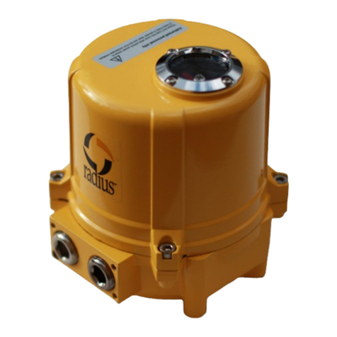
Radius A Series Guide

1
RADIUS LLC
4922 Technical Drive
Milford, Mi 48381
SERIES A
OPERATION AND
INSTRUCTION MANUAL
There are two series of RADIUS rack & pinion air actuators: those with aluminum bodies and those with
nodular iron bodies. For a better understanding please refer to the table below.
Double action Single action
Aluminum actuators series 003 through 500 series 003 through 500
Cast iron actuators series 750 only series 750 only
The technical features of the aluminum actuators are listed below. If further information on nodular cast
iron is required, please contact RADIUS.
DESCRIPTION
RADIUS actuators are quarter turn actuators; that is to say that the actuator shaft turns 90°, although some
models can be ordered with turning angles of up to 180°. The design of these actuators uses the system of a
double rack – single pinion. One of the most outstanding features of RADIUS actuators, available only
with the aluminum models, is its proprietary, revolutionary double travel stop system. This system allows a
complete regulation of the opening and closing of the aperture without having to remove the covers.
The standard units produce a torque between 132 and 52,660 lb. in. at 80 psi that, together with the shaft’s
output range and its modular design, allows the attachment of a wide variety of control accessories.
ATTACHMENT OF THE ACTUATOR
The RADIUS actuators can be installed directly or by using an adapter on the shaft of any valve. They
have a female coupling machined directly on the shaft that meets DIN-3337 and ISO-5211 standards.
RADIUS also offers a complete range of accessories to complement any coupling concept.
INSTALLATION OF THE ACTUATOR
The RADIUS actuators are normally installed so that their longitudinal axis is parallel to the direction of
the pipeline. The actuators can be installed on top, on the side or underneath the valve they are to attach to
without affecting their operation in anyway.
The actuator output shaft is completely machined and in the shape of an eight pointed star, following DIN-
3337 and ISO-5211 standards, which allows the actuator to be oriented in a way that can adapt to nearly
every installation.

2
RADIUS LLC
4922 Technical Drive
Milford, Mi 48381
SERIES A
OPERATION AND
INSTRUCTION MANUAL
The necessary steps for the proper installation of an actuator onto a valve are the following:
a. Determine the valve’s type of operation.
b. Determine the quadrant and the direction in which the actuator will be installed (i.e., perpendicular or
parallel to the fluid line.)
c. The connection of the assembly, support/actuator/valve, must be done in the following manner:
1. Rotate the actuator shaft to the desired position.
2. Install the valve support. At this time, the bolts must not be completely tightened.
3. Place the coupling on the valve shaft, making sure that it is correctly placed.
4. Set the actuator on the valve, making sure that the coupling is correctly inserted in the actuator
shaft.
5. Secure the support to the valve using the proper bolts and tighten all the bolts.
6. At this point, check that the actuator and the valve are in the desired position.
7. In the event that it is not correctly positioned, remove the actuator and repeat all the steps.
WARNING: NEVER REMOVE A PRESSURIZED ACTUATOR!
FEATURES AND OPERATING PRINCIPLES
1. Basic Actuator
The RADIUS actuator shaft rotates a full 90° (some models can be ordered with a 180° rotation angle).
The opening rotation is achieved, both in the double and single action models, by supplying air pressure
into the piston chambers. This thereby forces them to move in opposite directions and separating them one
from the other, resulting in a counterclockwise rotation of the shaft. At the end of the travel the actuator
will be in the open position.
In the double action actuators, the closing movement is obtained by supplying air pressure to the chambers
in both covers, forcing the pistons to move in opposite directions. This causes the pistons to draw nearer to
each other. Consequently, the shaft rotates clockwise obtaining the closed position at the end of the travel.

3
RADIUS LLC
4922 Technical Drive
Milford, Mi 48381
SERIES A
OPERATION AND
INSTRUCTION MANUAL
Closing of the single action actuators is obtained by the force the springs in the chambers of the covers
exercise on the pistons, forcing them to move in opposite directions drawing them together, achieving the
same result as in the double action actuators.
If a change in the direction of rotation is required, it is sufficient to rotate the pistons 180°.
2. Manual Operation
In the event of an air supply failure, the RADIUS actuators can be operated manually. This can be done
using an adjustable wrench on the upper part of the actuator shaft, turning it in the desired direction.
RADIUS also offers a varied range of declutchable gear operators for this operation. For more information
consult RADIUS.
WARNING: MAKE SURE THAT THE ACTUATOR IS NOT OPERATING
AUTOMATICALLY WHEN A MANUAL OPERATION IS BEING
PERFORMED.
NOTE: A PROPER RELEASE OF AIR IS REQUIRED FOR MANUAL
OPERATION. THIS REQUIRES THE DISCONNECTION OF THE AIR LINES
OR THE USE OF THREE WAY VALVES AT THE AIR PORTS.
STANDARD ACTUATION TIMES
The normal actuation times for RADIUS actuators are shown in the following table. The times are in
seconds and they represent an average of the times in a non-load condition at a pressure of 80 psi. The
times shown are for double and single action actuators. The closure times for the single action actuators
depend on the number of springs used.

4
RADIUS LLC
4922 Technical Drive
Milford, Mi 48381
SERIES A
OPERATION AND
INSTRUCTION MANUAL
The following is a table of times; the values are simply a guide and should be used as an indication of the
speed that may be obtained.
INTERNAL AIR VOLUME ( CU. IN.) ACTUATION TIME ( SEC.)
MODEL
DOUBLE
ACTION
SINGLE ACTION
OPENING CLOSING OPENING CLOSING
AD/AS-003 8.5 9.6 <1 <1 1
AD/AS-005 10.1 11.4 <1 <1 1
AD/AS-008 21.9 27.5 <1 <1 1
AD/AS-012 32.6 40.3 <1 <1 1 - 2
AD/AS-020 49.2 55.5 <1 <1 1 - 2
AD/AS-030 68.6 83.8 1 - 2 1 – 2 2 - 3
AD/AS-040 150.0 116.1 1 - 2 1 – 2 2 - 4
AD/AS-060 161.2 194.7 2 - 4 2 – 4 3 - 6
AD/AS-100 240.1 269.1 3 - 5 3 – 5 5 - 8
AD/AS-200 383.9 491.3 5 - 8 5 – 8 8 - 11
AD/AS-250 467.5 533.6 6 - 8 6 – 8 10 - 14
AD/AS-370 863.1 1067.2 7 - 9 11 – 14 17 - 20
AIR SUPPLY AND ELECTRICAL INSTALLATION
A) AIR SUPPLY
RADIUS actuators are correctly lubricated at the factory. All lubricants are silicone free. The use of dry,
clean, air or gas is recommended for optimal operation. Although lubrication of the media is not essential,
it is recommended.
B) AIR PRESSURE SUPPLY
The standard double action actuator version requires 15 to 125 psi air pressure. The single action actuators
require between 40 to 125 psi air pressure.
C) AIR SUPPLY CONNECTIONS
- Without an electrically-operated valve

5
RADIUS LLC
4922 Technical Drive
Milford, Mi 48381
SERIES A
OPERATION AND
INSTRUCTION MANUAL
1) Double Action (AD Models)
First, the dust cover plugs from the air intake ports must be removed. After the plugs are removed, the air
supply lines must be connected to the two inlet ports that are located on the side of the actuator body:
Standard units operate in the following manner:
Port A: Counterclockwise rotation / opening the actuator.
Port B: Clockwise rotation / closing the actuator.
1) Single action (AS Models)
As in the double action actuators, the dust cover plugs must be removed first; then, the air supply line must
be connected to Port A.
-With an electrically-operated valve.
The air supply line(s) must simply be connected to the valve’s pressure inlet ports.
MAINTENANCE
CAUTION: DISCONNECT ALL AIR SUPPLY LINES AND ELECTRICAL
POWER BEFORE STARTING ANY MAINTENANCE WORK.
All the actuators are supplied sufficiently lubricated for their normal life. The lubricants are silicone free.
In the event that the actuators should require lubrication, the use of OPTIMOL OLIT2 grease is
recommended. Grease for high and low temperatures are also available, but please consult RADIUS before
using it.
In the case of especially hard working conditions, a periodic check of gaskets, bearings, grease and springs
is recommended. The periodical replacement of the above mentioned parts it is also recommended. For
this purpose, RADIUS has complete replacement parts kits available. These kits can be easily purchased
by contacting RADIUS or any of its distributors. (See replacement parts paragraph)
PORT A PORT B

6
RADIUS LLC
4922 Technical Drive
Milford, Mi 48381
SERIES A
OPERATION AND
INSTRUCTION MANUAL
RECOMMENDED SPARE PARTS
All seals, slip shoes, bearings and all non-reusable parts are included in the replacement parts kit.
Each replacement parts kit includes:
Item Description Quantity
4 Slip shoe 2
9 Slip bearing 2
8 Cover O-Ring 2
10 Piston O-Ring 2
11 Shaft lower O-Ring 1
12 Shaft upper O-Ring 1
14 Double seal O-Ring 1
17 Air O-Ring 4
20 Stop O-Ring 2
6 Outside sealing washer 1
7 Retention ring 1
All the replacement parts kits are identical for the double and single action versions and for all aluminum
actuators. RADIUS also recommends a spring replacement kit for each model. These spring must be
replaced in complete sets. In each kit of springs, both springs and pre-tensors are supplied.
Model Quantity
AS-003 6
AS-005 12
AS-008/AS-012/AS-020 16
AS-030/AS-040 20
AS-060/AS-100 20
AS-200/AS-370 20
AS-140 24
AS-250
AS-500
40
42
STORAGE
When an actuator is not put in service immediately (or is used intermittently), it is recommended that the
actuator is operated at least three times a month using compressed air or nitrogen. When it is not possible
to operate them with air or nitrogen, and they can be operated manually (see PRINCIPLES OF MANUAL
OPERATION). It is recommended that they are stored indoors when space is available. Care must be
taken to plug up the openings to prevent the entry of foreign material and humidity. The actuators must not
be stored in places where the atmosphere is detrimental to the elastic seals.

7
RADIUS LLC
4922 Technical Drive
Milford, Mi 48381
SERIES A
OPERATION AND
INSTRUCTION MANUAL
DISASSEMBLY AND ASSEMBLY OF AN ACTUATOR
Although assembly and disassembly of an actuator is not recommended, in certain cases it might be
necessary to do so. For the disassembly and subsequent assembly of the actuator, follow the following
steps:
1. Remove all the control accessories or any type of accessory that is attached to the actuator.
2. Remove stop nuts (18) and the outside stops (19).
3. Remove the internal screw stops (16).
4. Unscrew and remove the cover bolts (15).
5. Carefully remove the covers (5).
6. The pistons (2) can be removed rotating the shaft (3) in counterclockwise direction.
7. Remove retention ring (7) and nylon washer (6).
8. Check that the shaft does not have any sharp edges that can damage the actuator’s body. If it does not
have sharp edges, remove the piston from its bore.
To reassemble the actuator it is necessary to perform the following steps:
1. When replacing the O-Rings, care must be taken to insure that all the parts are completely clean and
that all the seal seats are lightly greased.
2. The gears, the spring bores, and the springs themselves must be abundantly greased before assembling.
3. Replace the shaft (3) in its bore; subsequently insert the pistons (2). When mounting an actuator, the
side where the NAMUR valve is mounted should be facing you.
4. Do not engage the pistons until the groove on the upper side of the shaft (3) is correctly aligned. This
groove on the upper part of the shaft must form a 45° angle to the right, with each of the two axis of
the plane that forms the upper part of the actuator.
5. Simultaneously push the piston (2) into the body (1) to insure that the rack and pinion engage
correctly. The shaft will then rotate in a clockwise direction.

8
RADIUS LLC
4922 Technical Drive
Milford, Mi 48381
SERIES A
OPERATION AND
INSTRUCTION MANUAL
SINGLE ACTION ACTUATOR
When it is necessary to replace the springs of a single action actuator, make sure that the springs are
installed in the same position as before.
When less springs than usual are used, they must be installed as shown below.
AS005A / (AS003A)
6(3) Spring Set 8(4) Spring Set 10(5) Spring Set
AS008A / AS012A / AS020A
8 Spring Set 12 Spring Set
10 Spring Set 14 Spring Set

9
RADIUS LLC
4922 Technical Drive
Milford, Mi 48381
SERIES A
OPERATION AND
INSTRUCTION MANUAL
AS030A / AS060A / AS100A / AS200A / AS370A
10 Spring Set 12 Spring Set 14 Spring Set
16 Spring Set 18 Spring Set
Install the springs over the piston face within the seats that are on the piston.
Install the cover over the springs, aligning them with their appropriate seats in the cover.
Install the cover screws in the retention holes that are in the covers. If it is desired to convert a double
action unit into a single action unit, it is only necessary to install the springs.
Tighten the screws in the threaded bores in the actuator, forcing them slowly down into the cover. Tighten
each screw with small equal turns.

10
RADIUS LLC
4922 Technical Drive
Milford, Mi 48381
SERIES A
OPERATION AND
INSTRUCTION MANUAL
ADJUSTMENT OF THE ACTUATOR STOPS
Another outstanding feature of the Radius actuator is patented double travel stops that are provided
standard on all series A actuators. This system allows for the adjustment of the open and close position
without having to disassembly the actuator. Execute the following to conveniently regulate a Radius
actuator.
WARNING! Do not put your fingers close to any moving parts.
1. Install a pneumatic control valve or connect air lines to the A and C ports.
2. Loosen the stop nut (18).
3. Unscrew the stud bolt, O-ring and stop nut assembly (19), (20), and (18) so that they come out of the
housing in one piece.
4. Loosen or tighten the internal stop screw (16) according to whether more or less travel has to be given
to the actuator closing. It is very important that the two screws are adjusted equally.
5. Once the internal stop screw is adjusted, connect the air to port A to start the actuator’s opening
process and screw the assembly formed by the stud bolt, O-ring and stop nut (19), (20), and (18) until
it touches the head of the internal stop screw (10).
6. Tighten the stop nut (20) to prevent the stop stud (19) from loosening.
7. Care must be taken that the two internal stop screws (16) and the internal stop studs (10) are equally
tight. This is obtained by adjusting one of them to the desired position and then tightening the other
until an increase of stress is noticed.

Trouble Shooting Radius Actuators
The Radius rack and pinion pneumatic actuator is manufactured of high quality
materials and is designed to give long trouble free service life. It is not uncommon
for these actuators to produce over one million complete cycles before maintenance
or replacement is required. Below is a table of possible problems and fixes that may
occur during start-up or lifecycle. Please consult with your local representative or
the factory if this guide does not rectify any problem with the actuator.
Problem Possible Cause Fix
Actuator Doesn’t
Cycle
Air piping incorrect Check Air Piping/ see IOM
Air ports blocked Detach air lines and remove debris
Air supply is too low Increase air supply at regulator
Pilot valve malfunction Check proper operation of pilot valve
/ replace
Seals are worn Rebuild with new seal kit
Actuator undersized for application Replace with larger actuator
Actuator seized during winter / outside application/
water in compressed air
Thaw actuator/ remove water /Install
air dryer
Actuator is in a corrosive environment and corroded Clean and Repair/ install breather
block assembly.*
Actuator installed improperly on valve Check for proper installation/ correct
* The Radius actuator is corrosion resistant inside and out by design. There may be
instances of environmental chemicals that attack the actuator and can cause failure.
These instances are rare so please consult the factory before assuming the failure is
do to corrosion.
This manual suits for next models
24
Table of contents
Other Radius Controllers manuals