Rae MMU2-1600G Series User manual

This manual contains technical information for the
MMU2-1600G and MMU2-1600GE series Malfunction Management Unit
pn 889-3819-00 Revision: April 2020
MMU2-1600G series
Malfunction Management Unit
Firmware Version 02.00.05
Operations Manual
NEMA TS 2 Amendment 4-2012 Malfunction Management Unit
16 Configuration Types of Flashing Yellow Arrows


THE FOLLOWING PRODUCT WAS DESIGNED, INSPECTED, TESTED AND
MANUFACTURED IN THE USA BY EBERLE DESIGN, INC. IN PHOENIX, ARIZONA.
INFORMATION CONTAINED HEREIN IS PROPRIETARY TECHNICAL INFORMATION OF
EBERLE DESIGN, INC. PUBLICATION, REPRODUCTION OR USE IN WHOLE OR PART IS
NOT PERMITTED EXCEPT UNDER TERMS AGREED UPON IN WRITING. ALL
REGISTERED TRADEMARKS OF EBERLE DESIGN INC. ARE UNDER
© COPYRIGHT
MAINTENANCE NOTE
IT IS AN EBERLE DESIGN, INC. RECOMMENDATION THAT EACH UNIT BE TESTED
AT LEAST ANNUALLY TO ENSURE COMPLIANCE WITH FACTORY
SPECIFICATIONS AND MEETS PROPER OPERATIONAL STANDARDS. THE
RESULTS OF THIS TESTING WILL BE DOCUMENTED.


MMU2-1600GE Series Operations Manual
Table of Contents
Section 1 General Description............................................................................................1
Section 2 General Characteristics......................................................................................3
2.1 Inputs3
2.1.1 AC Line ............................................................................................................3
2.1.2 AC Neutral........................................................................................................3
2.1.3 Earth Ground....................................................................................................3
2.1.4 Field Terminals (Reds, Yellows, Greens, and Walks)......................................3
2.1.5 Red Enable ......................................................................................................3
2.1.6 Logic Ground....................................................................................................4
2.1.7 +24V Monitor I..................................................................................................4
2.1.8 +24V Monitor II.................................................................................................4
2.1.9 24V Monitor Inhibit ...........................................................................................4
2.1.10 Controller Voltage Monitor (CVM)..................................................................4
2.1.11 Type Select ....................................................................................................4
2.1.12 Local Flash Status..........................................................................................4
2.1.13 Port 1 Disable.................................................................................................5
2.1.14 Reset..............................................................................................................5
2.1.15 Cabinet Interlock ............................................................................................5
2.2 Outputs......................................................................................................................5
2.2.1 Output Relay ....................................................................................................5
2.2.2 Start Delay Relay .............................................................................................5
2.3 Programming Card ....................................................................................................5
2.3.1 Channel Compatibility......................................................................................6
2.3.2 Minimum Flash.................................................................................................6
2.3.3 Minimum Yellow Change Channel Disable......................................................6
2.3.4 Voltage Monitor Latch ......................................................................................6
2.3.5 Serial EEPROM ...............................................................................................6
2.4 FEATURES................................................................................................................6
2.4.1 Monitor Power Failure......................................................................................6
2.4.2 Minimum Flashing Indication............................................................................6
2.4.3 Reset................................................................................................................7
2.4.4 Type 16 Only Mode..........................................................................................7
2.4.5 COM Port .........................................................................................................7
2.4.6 Ethernet Port....................................................................................................7
2.4.7 Temperature Sensor ........................................................................................7
2.4.8 Real Time Clock...............................................................................................7
2.4.9 Up Time Accumulator.......................................................................................8
2.4.10 Configuration Monitoring (Beeping Monitor) ..................................................8
2.4.11 Factory Settings .............................................................................................8
2.4.12 User Unit Information .....................................................................................8
2.5 Fault Monitoring.........................................................................................................8
2.5.1 Conflict Monitoring ...........................................................................................8
2.5.2 Red Fail Monitoring..........................................................................................9
2.5.3 Dual Indication Monitoring..............................................................................10
2.5.4 GY-Dual Indication Monitoring.......................................................................11
2.5.5 Short Yellow Monitoring .................................................................................11
2.5.6 Short Clearance Monitoring ...........................................................................12
2.5.7 Field Check Monitoring ..................................................................................13
2.5.8 Port 1 Fail Monitoring.....................................................................................13
2.5.9 +24 Volt Monitor I...........................................................................................14
2.5.10 +24 Volt Monitor II........................................................................................14

2.5.11 Controller Voltage Monitor ...........................................................................14
2.5.12 Local Flash...................................................................................................15
2.5.13 External Watchdog Monitoring.....................................................................15
2.5.14 Programming Card Absent Monitoring.........................................................16
2.6 Testing Modifiers .....................................................................................................16
2.6.1 Flashing Don’t Walk Monitoring .....................................................................16
2.6.2 PPLT5 Monitoring ..........................................................................................16
2.6.3 Flashing Yellow Arrow Monitoring (FYA) .......................................................16
2.6.4 LED Thresholds .............................................................................................17
2.6.5 Per Channel Red Enable ...............................................................................18
2.6.6 Modified CVM Latch.......................................................................................18
2.6.7 12 Volt DC Monitoring....................................................................................18
2.6.8 Disable Local Flash........................................................................................19
2.6.9 Flashing Green (Canadian Fast Flash)..........................................................19
2.6.10 Channels with Pedestrain Displays..............................................................19
2.7 Event Logging..........................................................................................................19
2.7.1 Time Change Log...........................................................................................19
2.7.2 Monitor Reset Log..........................................................................................20
2.7.3 Configuration Event Log.................................................................................20
2.7.4 Prior Faults Log..............................................................................................20
2.7.5 AC Line Log ...................................................................................................20
2.7.6 Signal Sequence Log.....................................................................................20
2.7.7 Logging Options.............................................................................................20
2.7.7.1 Log Field Changes................................................................................20
2.7.7.2 Log Local Flash Events ........................................................................20
2.7.7.3 Log CVM Events...................................................................................20
2.8 Diagnostics..............................................................................................................20
2.8.1 Memory ..........................................................................................................21
2.8.2 Microprocessor Monitor..................................................................................21
2.8.3 Internal Voltage Monitors ...............................................................................21
2.8.4 Diagnostic Codes...........................................................................................21
Section 3 Specifications....................................................................................................22
3.1 Physical ...................................................................................................................22
3.2 Eectrical...................................................................................................................22
3.3 Timing Functions .....................................................................................................23
3.4 Connector Pin Assignments ....................................................................................24
3.5 Programming Card Pin Assignments.......................................................................26
3.6 Programming Card Minimum Flash Programming ..................................................26
Section 4 User Interface ....................................................................................................27
4.1 Graphic Display Menu Structure..............................................................................28
4.2 Front Panel Display and Pushbuttons .....................................................................29
4.3 Help System ............................................................................................................29
4.4 Run Time Display ....................................................................................................30
4.4.1 Normal............................................................................................................30
4.4.2 Fault ...............................................................................................................30
4.4.3 Changes Pending...........................................................................................30
4.4.4 Upgrade Pending ...........................................................................................30
4.5 Voltage Displays......................................................................................................30
4.6 Main Menu...............................................................................................................30
4.6.1 Identification Menu.........................................................................................31
4.6.1.1 User Unit Information............................................................................31
4.6.1.2 Factory Unit Information .......................................................................31
4.6.1.3 Ethernet Settings..................................................................................31
4.6.2 Configuration Menu........................................................................................32
4.6.2.1 Fault Monitoring Menu..........................................................................32
4.6.2.2 General Settings...................................................................................42
4.6.3 Logging System .............................................................................................42

4.6.3.1 View Logs .............................................................................................43
4.6.3.2 Clear Logs ............................................................................................44
4.6.3.3 Clear All Logs .......................................................................................44
4.6.3.4 AC Logging Events Thresholds............................................................44
4.6.4 Date & Time Menu .........................................................................................45
4.6.4.1 View / Set Date and Time.....................................................................45
4.6.4.2 View / Set Daylight Saving Time Ahead...............................................45
4.6.4.3 View / Set Daylight Saving Time Back..................................................45
4.6.4.4 View Up Time .......................................................................................45
4.6.5 Real Time Monitor Status Menu.....................................................................45
4.6.5.1 Channels 1-6 ........................................................................................45
4.6.5.2 Channels 7-12 ......................................................................................45
4.6.5.3 Channels 13-16 ....................................................................................45
4.6.5.4 Other AC and Miscellaneous Inputs.....................................................46
4.6.5.5 DC Inputs..............................................................................................46
4.6.6 Diagnostic Info ...............................................................................................46
4.6.6.1 LED Test Settings.................................................................................46
4.6.6.2 Screen Test ..........................................................................................46
4.6.6.3 Fault Codes ..........................................................................................46
4.6.6.4 Diagnostic SDLC Frames Menu...........................................................46
4.6.6.5 Firmware Versions................................................................................46
4.6.6.6 Diagnostic Statistics Menu....................................................................47
4.6.6.7 Factory Diagnostics..............................................................................47
4.7 Front Panel LED Indicators......................................................................................47
4.7.1 Field Status Indicators....................................................................................47
4.7.2 Power / Type Indicators .................................................................................48
4.7.3 Transmit / Receive Indicators.........................................................................48
4.7.4 Fault Indicators...............................................................................................48
4.7.5 Function Disabled Indication..........................................................................48
4.8 Audible Buzzer.........................................................................................................49
4.8.1 Critical Failure ................................................................................................49
4.8.2 Configuration Change ....................................................................................49
Section 5 Firmware Upgrade.............................................................................................50


889-3819-00 MMU2-1600GE series Operations Manual Rev Apr 2020 Page 1of 51
Section 1 General Description
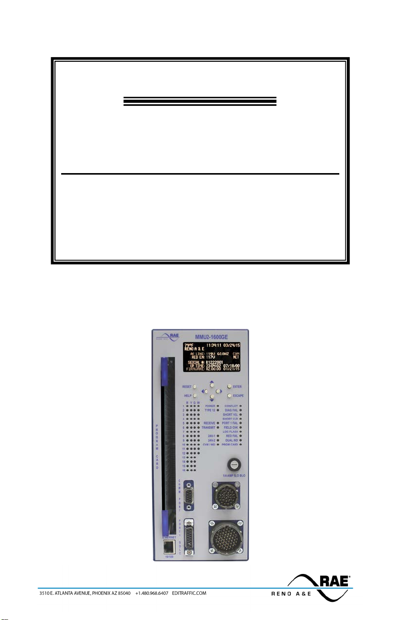
This product manual was written for people installing, operating, and maintaining the Reno A&E Model MMU2-
1600G Malfunction Management Unit (monitor).
The Reno A&E MMU2-1600G was designed to meet or exceed the standards defined in Section 4 of the NEMA
Standards Publication TS 2-2003 and Amendment 4-2012. Section 4 responds to the need for a monitor to
accomplish the detection of, and response to, improper and conflicting signals and improper operating voltages in a
Controller Assembly (CA). This standard provides interchangeability between units of different manufacturers and
downward compatibility to NEMA Standards Publication TS 1-1989. Amendment 4-2012 defines eight types of
Flashing Yellow Arrow (FYA) operation. The MMU2-1600G supports the eight FYA types defined in Amendment
4 and eight additional types of FYA operation.
The MMU2-1600G detects the presence of voltage on conflicting field connection terminals, the absence of proper
voltages on all of the signal field connection terminals of a channel, and monitors for the presence of satisfactory
operating voltages within the Controller Unit (CU) and the monitor itself. If any of these conditions exist or are
out of tolerance for the minimum time defined in Section 4 of the NEMA Standards Publication TS 2-2003, the
Output relay’s normally open contacts will transfer from the no fault state (relay energized) to the fault state (relay
de-energized). The closure of the Output relay contacts will cause the transfer of the traffic signals to Flashing
Operation. The fault is recorded by the MMU-1600G and displayed on the appropriate LED indicators.
The MMU2-1600G will operate in one of two modes depending on the signal level on the Type Select input. If the
Type Select input is at Logic Ground potential, the monitor will operate as a Type 16 monitor with sixteen
channels, otherwise it will operate as a Type 12 monitor with twelve channels.
Type 16 - Each of the sixteen channels monitors three 120 volt AC outputs; Green / Walk, Yellow, and Red /
Don’t Walk.
Type 12 - Each of the twelve channels monitors four 120 volt AC outputs; Green, Yellow, Walk, and Red.
For TS 2 type operation the MMU2-1600G is usually configured as a Type 16 monitor. The Type 16 monitor is
intended for those applications in which there are three circuits per channel and the monitor channels have been
wired in a one-to-one correspondence with the load switches, as defined in Section 5.5.3, Paragraph 9 of the
NEMA Standards Publication TS 2-2003. The Type 12 monitor is intended to provide downward compatibility
with a 12 channel conflict monitor unit (CMU) conforming to TS 1-1989.
The signal monitor portion of the monitor is capable of checking for the presence of voltage on conflicting field
connection terminals in the Controller Assembly. For the purpose of conflict determination, a signal on any of the
Green, Yellow, or Walk inputs associated with a channel shall be considered as that channel being active.
The signal monitor portion of the monitor is also capable of checking for the absence of any required signal voltage
on each channel at the field connection terminals in the Controller Assembly. For this purpose a signal on the
Green, Yellow, Walk, or Red/Don’t Walk inputs associated with a channel shall be considered as that channel
being active.
The voltage monitor portion of the monitor is capable of checking the Controller Unit Voltage Monitor output that
indicates satisfactory operating voltage in the Controller Unit and the +24 volt direct current inputs.
The Model MMU2-1600G is fully programmable. The monitor has a unique graphics based Organic Light
Emitting Diode (OLED) display. The OLED display allows access to all configuration settings, real-time monitor
status with applicable AC and DC voltages, advanced diagnostic information, all logs including the most current
signal sequence log, and context sensitive help screens.
An interchangeable programming card is provided to allow the assignment of permissive or compatible channels.
Programming is accomplished through the use of soldered wire jumpers on the programming card. The
programming card may be used in a monitor operating in either Type 16 or Type 12 mode. The programming card
can be inserted into the monitor through a slot in the front panel. The programming card also contains a serial
EEPROM. This device is used to store programming information not set by the wire jumpers. Features stored in
the serial EEPROM include Flashing Don’t Walk Monitoring, Co-Channel Childs, Per Channel Red Enable,
Location, Unit ID, Agency ID, IP Address, and others.
When configured in the Type 16 mode and connected to a TS 2 Controller Unit, the monitor has the ability to
exchange information in a standardized format with the Controller Unit in real time through the Port 1 interface.
The monitor and the Controller Unit perform redundant checks on each other through messages defined in the TS 2
Standard. The Controller Unit can access monitor information including field signal input status, permissive
programming, and fault status. This gives the Controller Unit the capability to function as a backup monitor and
make enhanced event logging, remote intersection monitoring, and remote diagnostics possible. Likewise, the
monitor receives information from the Controller Unit corresponding to Controller Unit output commands to the

889-3819-00 MMU2-1600GE series Operations Manual Rev Apr 2020 Page 2of 51
various load switches. Access to this information allows the monitor to more accurately respond to and diagnose
fault situations.
Requirements outlined in the TS 2 Standard provide for messages to be generated by the Controller Unit and the
monitor, which effectively extend the communications capabilities of a standard assembly. The monitor utilizes
these message facilities to provide the highest level of enhanced application specific diagnostic reporting and
monitoring.
The Model MMU2-1600G Series is comprised of the following monitors:
Model MMU2-1600G (Reno USA) For applications calling for a NEMA TS 2-2003
compliant Malfunction Management Unit with
integral graphics display.
Model MMU2-1600G (Reno Canada) For applications calling for a NEMA TS 2-2003
compliant Malfunction Management Unit with
integral graphics display and Canadian Fast Flash
monitoring.
Model MMU2-1600GE (Reno USA) For applications calling for a NEMA TS 2-2003
compliant Malfunction Management Unit with
integral graphics display and optional Ethernet
network connector.
Model MMU2-1600GE (Reno Canada) For applications calling for a NEMA TS 2-2003
compliant Malfunction Management Unit with
integral graphics display and Canadian Fast Flash
monitoring and optional Ethernet network
connector.

889-3819-00 MMU2-1600GE series Operations Manual Rev Apr 2020 Page 3of 51
Section 2 General Characteristics
2.1 INPUTS
2.1.1 AC LINE
The over-current protected side of 120 volt AC 60 hertz source. This input (Connector A - Pin A) is used to
generate the voltages required to operate the monitoring logic. The monitor has a front panel mounted over-current
protection device in the 120 volt AC input to the unit. This fuse is a 1/4 AMP SLO-BLOW and should only be
replaced with a fuse of the same type and value.
Typical Connection: Cabinet AC Line power source.
2.1.2 AC NEUTRAL
The unfused and unswitched return side of the 120 volt AC 60 hertz power source. This input (Connector A - Pin
V) is the referenced signal for all field terminal voltage sensing inputs. This input is not connected to Logic
Ground or Earth Ground within the unit.
Typical Connection: Cabinet AC Neutral.
2.1.3 EARTH GROUND
The monitor has an input terminal (Connector A - Pin U) providing an independent connection to the chassis of the
unit. This input is not connected to Logic Ground or AC Neutral within the unit.
Typical Connection: Cabinet Earth Ground.
2.1.4 FIELD TERMINALS (REDS, YELLOWS, GREENS, AND WALKS)
The field terminal inputs are where the Red, Yellow, Green, and Walk indications are connected to the monitor.
The inputs used and how they are used is determined by the state of the Type Select input (See Section 2.1.11).
Type 16: Three inputs are provided for each channel to permit the monitoring of voltages at the Green, Yellow,
and Red signal field terminals. If the channel is used to monitor pedestrian indication, they are connected Don’t
Walk to Red, Pedestrian Clearance to Yellow, and Walk to Green.
Type 12: Four inputs are provided for each channel to permit the monitoring of voltages at the Green, Yellow,
Red, and Walk signal field terminals.
The thresholds used to determine the ON and OFF states of the field terminals can be modified from the standard
(incandescent) thresholds to ones more appropriate for LED field displays. The LED thresholds are more
restrictive than the standard thresholds. Therefore, you will not miss a fault using the LED thresholds that would
have been detected using the standard thresholds.
In the Standard Mode (Incandescent Field Displays):
A Green, Yellow, or Walk signal input is sensed as ON when it exceeds 25VRMS and a signal input is sensed
as OFF when it is less than 15VRMS. Signals between 15VRMS and 25VRMS may be in either state.
A Red signal input is sensed as ON when it exceeds 70VRMS and a signal input is sensed as OFF when it is
less than 50VRMS. Signals between 50VRMS and 70VRMS may be in either state.
In the LED mode (LED Field Displays):
For the purpose of testing for Conflicts, Multiple Indications, and Flashing Don’t Walk Monitoring, a Green,
Yellow, Red, or Walk signal input is sensed as ON when it exceeds 25VRMS and a signal input is sensed as
OFF when it is less than 15VRMS. Signals between 15VRMS and 25VRMS may be in either state.
For the purpose of testing for Red Fails, Co-Channel Childs, Short Yellows, and Short Clearance, a Green,
Yellow, Red, or Walk signal input is sensed as ON when it exceeds 70VRMS and a signal input is sensed as
OFF when it is less than 50VRMS. Signals between 50VRMS and 70VRMS may be in either state.
When the load connected to the sensing input of the monitor exhibits high impedance characteristics such as those
caused by some LED signal displays or burned out lamps, it may be necessary to place a low impedance device
(load resistor) external to the unit between the unit input and AC Neutral. See Section 6.2.4 of NEMA Standards
Publication TS 2-2003.
Typical Connections: Field terminals for channel Reds, Yellows, Greens, and Walks as appropriate.
2.1.5 RED ENABLE
The presence of the proper voltage at this terminal (Connector B - Pin a) enables the monitor to detect
the absence of voltage on all field signal inputs of a channel. The absence of the proper voltage inhibits
the detection of the absence of voltage on all field signal inputs of a channel. This input is considered
enabled when the input voltage exceeds 89VRMS at the Red Enable input. This function is considered
not enabled when the input voltage is less than 70VRMS at the Red Enable input.

889-3819-00 MMU2-1600GE series Operations Manual Rev Apr 2020 Page 4of 51
The presence of the proper voltage at this terminal also enables Minimum Yellow Change / Red
Clearance Interval Monitoring and Field Check / Dual Indication Monitoring. The absence of the proper
voltage at this terminal inhibits Minimum Yellow Change / Red Clearance Interval Monitoring.
The monitor will not recognize state changes of the Red Enable input while AC power is not valid. This
ensures that short power interruptions do not cause unintended state changes of the Red Enable input.
Typical Connection: Control point that has 120VAC when the cabinet is in normal operation.
2.1.6 LOGIC GROUND
A voltage reference point and current return for the Reset input, Controller Voltage Monitor input, +24V Monitor I
input, +24V Monitor II input, Type Select input, +24V Monitor Inhibit input, Local Flash Status input, and Port 1
Disable input as well as the Port 1 SDLC communications signals. This termination (Connector A - Pin T) is not
connected to either the AC Neutral or Earth Ground within the unit.
Typical Connection: Power Supply DC Common and/or Controller Logic Ground.
2.1.7 +24V MONITOR I
+24V Monitor I (Connector A - Pin S) is monitored to assure a proper +24 volt DC level.
Typical Connection: Power Supply +24VDC or Controller +24VDC Output.
2.1.8 +24V MONITOR II
+24V Monitor II (Connector B - Pin R) is monitored to assure a proper +24 volt DC level. This input can
optionally be used to monitor a +12VDC supply (detector power) if the 24V-2 to 12VDC feature is enabled.
Typical Connection: Power Supply +24VDC, Controller +24VDC Output, or Power Supply +12VDC.
2.1.9 24V MONITOR INHIBIT
+24V Monitor Inhibit input (Connector A - Pin n) is a logic level input used to disable monitoring of the +24V
Monitor I and +24V Monitor II inputs. Application of a True (Low) state to this input inhibits the operation of the
+24 Volt Monitor and sets the +24 Volt Monitor Inhibit bit (bit 60) of the Type 129 Frame to 1.
Typical Connection: Unterminated or tied to +24VDC.
2.1.10 CONTROLLER VOLTAGE MONITOR (CVM)
The Controller Voltage Monitor input (Connector A - Pin V) is a logic level input. This input must stay in a low
state (nominal 0 volts) for normal signal operation. When high or floating, the monitor will be in the fault
condition. This input is sometimes used by controllers to perform time of day flash operations. In this case, the
24V Latch jumper on the program card cannot be installed for proper operation.
Typical Connection: Controller CVM Output
2.1.11 TYPE SELECT
The monitor operates as a Type 16 monitor with sixteen channels when the Type Select input (Connector A - Pin
HH) is at logic True (Low) state; otherwise it operates as a Type 12 monitor with twelve channels.
Type 16: When configured for Type 16 operation, each channel has the capability of monitoring a Green (Walk), a
Yellow, and a Red (Don’t Walk) field signal output at the Terminals and Facilities field terminals. Type 16
operation is intended for those applications in which there are three circuits per channel and the monitor channels
have been wired in a one-to-one correspondence with the load switches, as defined in Section 5.5.3, Paragraph 9 of
the NEMA Traffic Controller Assemblies Standards Publication TS 2-2003.
Type 12: When configured for Type 12 operation, each channel has the capability of monitoring a Green, a Walk,
a Yellow, and a Red field signal output at the Terminals and Facilities field terminals. Type 12 operation is
intended for those applications in which downward compatibility with 12 channel Conflict Monitor Units (CMU)
conforming to NEMA Traffic Control Systems Publication TS 1-1989 is required. All Port 1 communications
errors are ignored when the monitor is configured to operate as a Type 12 monitor.
Typical Connection: Logic Ground for Type 16 operation. Unterminated or tied to +24VDC for Type 12 operation.
2.1.12 LOCAL FLASH STATUS
The Local Flash Status input (Connector B - Pin c) is a logic level input. When this input is in the low state
(nominal 0 volts), the monitor will transfer the Output Relay contacts to the fault state and set the Local Flash
Status bit (bit 79) in the Type 129 Frame to 1. At all other times, the Local Flash Status bit of the Type 129 Frame
is set to 0.
Typical Connection: Police Panel flash switch and/or inside cabinet flash switch

889-3819-00 MMU2-1600GE series Operations Manual Rev Apr 2020 Page 5of 51
2.1.13 PORT 1 DISABLE
The Port 1 Disable input (Port 1 SDLC Connector - Pin 10) is a logic level input. When this signal is in the low
state (nominal 0 volts), the monitor will ignore Port 1 SDLC communications errors. Port 1 SDLC
communications errors are always ignored during type 12 operation.
Typical Connection: Unterminated when Port 1 SDLC communications will be used. Logic Ground when Port 1
SDLC communications are not used in Type 16 operation.
2.1.14 RESET
The Reset input (Connector A - Pin BB) is a logic level input. When this input transitions to the low state (nominal
0 volts), a fault reset is performed.
Typical Connection: Unterminated or tied to +24VDC. Should be used only for automated testing.
2.1.15 CABINET INTERLOCK
The monitor has two terminals internally connected to indicate the presence of the unit to external circuitry. These
terminals are identified as Cabinet Interlock A (Connector A - Pin CC) and Cabinet Interlock B (Connector A - Pin
DD).
Typical Connection: Interlock circuitry that will not allow the cabinet to operate normally with the monitor
removed.
2.2 OUTPUTS
2.2.1 OUTPUT RELAY
The Output relay of the monitor has two sets of isolated Form C contacts. These relay contacts are capable of
switching all loads in the range from two milliamps at 18 volts DC to three amperes at 135VRMS AC.
The Normally Open (N.O.) contacts of the Output relay are the contacts that are open when the unit is in the No
Fault state and all voltages are sufficient for proper operation of the Controller Assembly. The relay coil is
energized in the No Fault state.
Prior to the monitor transferring the Output relay contacts from the Fault state to the No Fault state, a Transition
state with a duration of 500 milliseconds occurs. During the Transition state the Output relay contacts are the same
as the Fault state and the monitor sets the Start-Up Flash Call bit (bit 80) of the Type 129 Frame to 1. At all other
times the Start-Up Flash Call bit of the Type 129 Frame is set to 0.
Typical Connection: One set of contacts is used to control the flash transfer relays the other is usually used to apply
stop timing to the controller.
2.2.2 START DELAY RELAY
The Start-Delay relay has one set of Form C relay output contacts. These relay contacts are capable of switching
all loads in the range from 2 milliamps at 18 volts DC to 3 amperes at 135VRMS AC.
The monitor includes a means of detecting a loss of AC Line power. Upon restoration of AC Line following a
monitor power loss, the Start-Delay relay maintains continuity between its Common and Normally Open contacts
for a period of 2.0 ±0.5 seconds. Following this 2.0 second time period, the Start-Delay relay enables continuity to
occur between its Common and Normally Closed contacts.
The operation of the Start-Delay relay normally results in the initiation of a start-up sequence within the Control
Unit by interrupting the AC Line input to the Control Unit.
Typical Connection: The Common and Normally Closed contacts are used to route AC power to the controller.
2.3 PROGRAMMING CARD
This monitor uses a standardized programming card for channel compatibility (permissives), minimum flash time,
per channel Minimum Yellow Change Disable, CVM latch, and 24 volt monitor latch. Programming of this card is
accomplished through the use of soldered wire jumpers. The programming card plugs into the monitor through a
slot in the front panel. The monitor is constructed with card guides to ease the insertion of the programming card.
The programming card includes card ejectors to ease removal of the programming card. The edge of the
programming card is flush with the surface of the front panel when it is properly seated in the programming card
slot of the monitor. The PRGM CARD LED will illuminate if the programming card is not properly seated while
power is applied.
Programming cards supplied by Reno A&E have an integral serial EEPROM which can store the other settings for
the monitor which are not programmed using soldered jumpers.
See Section 3.5 for programming card connector pin assignments.

889-3819-00 MMU2-1600GE series Operations Manual Rev Apr 2020 Page 6of 51
2.3.1 CHANNEL COMPATIBILITY
The monitor requires programming action to provide compatibility between channels.
The programming card has 120 pairs of holes for channel compatibility programming jumpers. The 120 jumper
hole pairs are logically labeled for easy identification of the jumper holes by channel pairs. A soldered wire
jumper in a jumper hole pair defines a pair of channels as permissive or compatible.
2.3.2 MINIMUM FLASH
The programming card has four pairs of holes for minimum flash programming jumpers. The four jumper hole
pairs are logically labeled for easy identification of the jumper holes in binary weighted fashion. A soldered wire
jumper in a jumper hole pair adds that designated input value to the binary weighted sum. Per the NEMA TS 2
standard, the actual value used is the binary weighted sum plus one.
2.3.3 MINIMUM YELLOW CHANGE CHANNEL DISABLE
The programming card has sixteen pairs of holes for Minimum Yellow Change Disable programming jumpers.
The sixteen jumper hole pairs are logically labeled for easy identification of the channel numbers. A soldered wire
jumper in a jumper hole pair disables Minimum Yellow Clearance monitoring for that channel. Typically, all
pedestrian channels should have these jumpers installed.
2.3.4 VOLTAGE MONITOR LATCH
The programming card has two pairs of holes for latch programming jumpers. The two jumper hole pairs are
logically labeled for easy identification of the +24 Volt Latch and CVM Latch. A soldered wire jumper in a
jumper hole pair causes that fault condition to be latched.
2.3.5 SERIAL EEPROM
The programming card contains a serial EEPROM. This device is not called for in the NEMA TS-2 specification
and is only compatible with other Reno A&E monitors. The programming card is interchangeable with other
manufacturer’s programming cards for the programming of the standard features. Reno A&E has provided the
serial EEPROM as a way of copying the other programming settings from one monitor to another monitor. Using
a non-Reno A&E programming card in this monitor will result in the monitor not being able to store the other
programming settings for copying to other Reno A&E monitors. See Section 2.4.10 for additional information on
how data stored in the serial EEPROM is used.
2.4 FEATURES
2.4.1 MONITOR POWER FAILURE
The monitor responds to a Power Failure by entering a non-latching flash state. The monitor responds to a Power
Failure whether it is the result of the over-current protection device operation, failure of the monitor power supply,
or absence of proper operating AC Line voltage as defined below.
The operating AC Line input is considered to be On if the voltage level is greater than 98VRMS AC and it is
considered to be Off if the voltage level is less than 89VRMS AC. The hysteresis from the Off state to the On state
or vice versa is at least 3VRMS AC.
The monitor responds to Power Failure as follows:
1) If the AC Line input is Off for 450 milliseconds or less, the monitor continues to operate as though the
AC Line had remained On. The Output relay contacts do not transfer to the fault condition during this
interval. The Start-Delay relay maintains continuity between its Common and Normally Closed contacts.
2) If the AC Line input is Off for 500 milliseconds or more, the monitor transfers the Output relay contacts
to the fault condition. The Start-Delay relay enables continuity between its Common and Normally Open
contacts. The time interval from the start of the AC Line input being Off and the transfer of both relays to
these states does not exceed 525 milliseconds. Both relays maintain these states for the duration of the
Power Failure.
2.4.2 MINIMUM FLASHING INDICATION
The monitor includes internal logic to enforce a user definable Minimum Flash time. Once the monitor has
transferred the Output relay contacts to the fault condition, the state of the Output relay contacts is maintained for
the Minimum Flash time before normal operation can resume.
All monitor initiated flash conditions will start the Minimum Flash timer. The monitor will not return to normal
operation until this timer has expired unless it is terminated by use of the front panel reset pushbutton or reset input
command which will cause an immediate transfer to the no fault state.
The duration of the Minimum Flash time is adjustable between the limits of 5 seconds and 15 seconds with an
incremental adjustment of one second and is programmed using jumpers on the Program Card. The NEMA TS-2
specification requires that the monitor add one second to whatever value is programmed on the program card and
that the value on the program card cannot be set to less than five seconds. This creates a useable range of 6
seconds to 16 seconds.

889-3819-00 MMU2-1600GE series Operations Manual Rev Apr 2020 Page 7of 51
2.4.3 RESET
Activation of the front panel reset pushbutton or the reset input causes the Output relay contacts to transfer to the
no fault condition. The monitor remains in the no fault condition only if there are no existing faults and all input
voltages are at the proper operating levels. If the Minimum Flash timer is active, activation of the either reset will
zero the timer and transfer to the no fault condition.
Each activation of the front panel reset pushbutton or the reset input causes a one-time reset input to the monitor.
A continuously activated front panel reset or reset input will not prevent the monitor from checking any fault
conditions and/or transferring the Output relay contacts to the fault condition. The front panel reset or reset input
must be removed and reapplied to activate a new reset input to the monitor. Activation of either reset will cause all
of the front panel LEDs to turn on for 300 milliseconds.
The only intended purpose of the reset input is to facilitate automated testing of the monitor.
2.4.4 TYPE 16 ONLY MODE
This feature if useful in cabinets where the user is retrofitting a TS 2 monitor into a TS 1 cabinet and wants to use
the Type 16 mode, but the existing Connector A harness does not have a wire for Pin HH (Type Select).
Activating this feature forces the monitor to operate in the Type 16 mode regardless of the logic level on the Type
Select input. While this feature is on, the TYPE 12 LED will show the Function Disabled indication (50
milliseconds on, once every two seconds).
2.4.5 COM PORT
The monitor has a front panel mounted DB-9, RS-232 communications port that can be used with Reno A&E’s
RaeComM software to view / modify configuration settings, view current status and voltages, view logs, and
download firmware upgrades. The COM port supports the standard baud rates from 300 to 57600 with one or two
stop bits and parity of odd, even, or none. The factory default is 57600, no parity, and one stop bit. The most
current version of the RaeComM software can be found on the Reno A&E web site www.editraffic.com under
support / monitor support / software. Also see Application Note AN-002 for an introduction to the RaeComM
software. This application note can be found on the web site under support / monitor support / application notes.
The monitor was designed to use a standard DB-9 extension cable (male to female, straight through) for connecting
to a laptop or computer. This port does not support handshaking signals. Both the COM port and the optional
Ethernet port can be used at the same time. See Section 3.4 for connector pin assignments.
2.4.6 ETHERNET PORT
The monitor has an optional high speed, 10BASE-T / 100BASE-TX Ethernet network jack that can be used for
communications with Reno A&E’s RaeComM software to view / modify configuration settings, view current
status and voltages, view logs, and download firmware upgrades.
To use this port an IP Address and port number must be set in the monitor. Contact your network administrator for
addresses valid for your network. The factory default is an IP Address of 192.168.1.150 (which is an unusable
address) and port 10001 (this is the recommend value).
In order to prevent the accidental writing of information to an unintended monitor, the Ethernet port is read-only on
power up. To make the Ethernet port read-write, press any pushbutton on the front of the monitor. This will
unlock the monitor for a period of 15 minutes.
2.4.7 TEMPERATURE SENSOR
The monitor is capable of monitoring the temperature inside of the cabinet. The temperature sensor is capable of
monitoring temperatures in the range of -40°F to +214°F (-40°C to +101°C). The internal cabinet temperature is
included in the data logged into the Prior Faults Log when a fault occurs. If the actual temperature inside the
cabinet is below -40°F (-40°C) at the time the fault occurs, the temperature is logged as -40°F (-40°C). If the
actual temperature inside the cabinet is above +214°F (+101°C) at the time the fault occurs, the temperature is
logged as +214°F (+101°C).
2.4.8 REAL TIME CLOCK
The monitor has a Real Time Clock (RTC) that is used as a reference for all date and time stamped events that are
logged by the monitor. The Real Time Clock is initialized to local Pacific Standard Time when the unit is
undergoing final test. In addition, the Daylight Saving Time user option is set to Off.
The Real Time Clock is preprogrammed to recognize Leap Years and Daylight Saving Time events through the
year 2099. Currently, per U.S. Federal standards, Daylight Saving Time is observed in the United States from 2:00
A.M. on the second Sunday in March until 2:00 A.M. on the first Sunday in November.
The update priority of any time setting that affects the Real Time Clock is as follows:
1. Controller Time - The Real Time Clock is programmed with the time setting received from the Controller.
This information is received via the PORT 1 SDLC connector on the front of the monitor. If the Real
Time Clock setting differs from the Controller Time setting by more than two (2) seconds, The Real Time
Clock will be synchronized to the Controller clock. In the event that the Real Time Clock setting differs

889-3819-00 MMU2-1600GE series Operations Manual Rev Apr 2020 Page 8of 51
from the Controller Time setting by five (5) or more seconds, the Real Time Clock will be synchronized
to the Controller clock and an entry will be made to the Time Change Log.
2. External Time Source (i.e. laptop computer) - The Real Time Clock setting can be modified through the
use of the RaeComM software. Connection to the laptop computer is made via the COMM PORT serial
connector or optional Ethernet connector on the front of the monitor. NOTE: Whenever the monitor is
connected to an operational SDLC bus, any time setting entered via the serial port will be overwritten by
the Controller Time setting.
3. Front Panel - The Real Time Clock setting can be modified through the front panel. NOTE: Whenever
the monitor is connected to an operational SDLC bus, any time setting entered via the front panel will be
overwritten by the Controller Time setting.
If it is necessary to change the Real Time Clock setting in a monitor that is being used in a NEMA TS 2 Cabinet
Assembly, change the time setting on the cabinet controller. The time change will be broadcast to the monitor
through the SDLC port.
2.4.9 UP TIME ACCUMULATOR
The monitor has an Up Time Accumulator that keeps track of the total amount of time that the monitor has been
powered up since it was manufactured. It is saved in the format of Years, Months, Days, Hours, Minutes, and
Seconds. The MMU-1600G warranty coverage is valid for a total accumulated Monitor Up Time of two (2) years.
Tracking and recording the total time that the unit was in service provides an accurate means of validating any
potential warranty claims.
2.4.10 CONFIGURATION MONITORING (BEEPING MONITOR)
The monitor checks all configuration settings for changes once each second. If a change is found, an audible
buzzer will start beeping to indicate that a configuration setting has changed except when the monitor is in one of
the configuration screens. This is to keep the buzzer from being too annoying when you know you are making
changes. However, if you leave the configuration menu the monitor will start beeping. If the change is undone,
the beeping will stop. No fault monitoring configuration changes are implemented until the front panel reset
pushbutton is pressed and held for five (5) seconds or the changes are saved using the Fault Configuration Menu.
At that time five quick confirmation beeps will be heard, the new settings will be implemented, and a
Configuration Change log entry made.
The following configuration settings are monitored: Programming Card jumpers, Type Select input, Factory
Options, Dual Indication / Field Check, Per Channel Red Enables, Flashing Don’t Walk Monitoring, Flashing
Yellow Arrow Left Turns, Co-Channels, Thresholds, Logging Enables, Disable Local Flash, Modified CVM
Latch, External Watchdog Enable, Type 16 Only, and Buzzer Disable.
On power up and any time the program card is changed the configuration stored on the program card is compared
to the configuration stored in the monitor. If they do not match the user is prompted to choose which data set to
use. If the program card is selected, the configuration settings on the card will be copied into the monitor. If the
monitor is selected, the configuration settings on the program card are overwritten with the current monitor
configuration. All user information (Ethernet settings, Location, Location ID, and Agency ID) as well as fault
monitoring settings are copied. See Section 4.10 for front panel display during selection of configuration source.
2.4.11 FACTORY SETTINGS
The monitor is configured at the factory during final test. Data set at the factory includes: Model Number, Serial
Number, Manufacture Date, Real Time Clock setting, Support for Flashing Greens, Enhanced Support of Econolite
Controllers, Support for a Diagnostic LCD. The Up Time Accumulator is initialized to zero prior to final testing.
Changes to Support for Flashing Greens, Enhanced Support of Econolite Controllers, and Support for a Diagnostic
LCD are logged in the configuration log.
2.4.12 USER UNIT INFORMATION
The monitor has non-volatile memory that can be used to store the following user unit information: 40 character
Location ID, 4 character Unit ID, and 5 character Agency ID. All of these IDs can consist of any alpha-numeric
characters. Upper and lower case characters can be used but all lower case will be displayed as uppercase on the
front panel graphic display.
2.5 FAULT MONITORING
2.5.1 CONFLICT MONITORING
Configuration: The jumpers installed on the Program Card determine permissive (non-conflicting) channels. A
jumper in the row labeled “2” and the jumper hole pair labeled “6” would make Channels 2 and 6 permissive with
each other. This is a two-way relationship. If channel 2 is programmed as permissive with channel 6 then channel
6 is automatically permissive with channel 2. The testing defaults for this feature are determined by the jumpers
installed on the program card. Typically no jumpers are installed during automated testing.
Test Preformed: While a channel has a Green, Walk, or Yellow display active, the channel is tested to see if a
non-permissive channel has a Green, Walk, or Yellow display active at the same time. If concurrently active

889-3819-00 MMU2-1600GE series Operations Manual Rev Apr 2020 Page 9of 51
conflicting displays are detected a conflict timer is started. If the conflict goes away the conflict timer is stopped
(it is not cleared) and a non-conflict timer is started. If the conflict reappears the non-conflict timer is reset to zero
and the conflict timer continues timing from its prior value. If the conflict timer reaches 300 milliseconds or more
the monitor will latch a conflict fault. If the non-conflict timer reaches 666 milliseconds the conflict timer is reset
to zero and the conflict is ignored. The normal voltage thresholds for this test are: Reds – ON when above 70VRMS
and OFF when below 50VRMS, Greens / Yellows / Walks – ON when above 25VRMS and OFF when below 15VRMS.
Fault Action: The monitor transfers the Output relay contacts to the fault condition (continuity between the
Normally Open and Common contacts), illuminates the CONFLICT indicator on the front panel, and sets the
Conflict bit (bit 65) of the Type 129 Frame to 1. The Signal Sequence log and the Prior Faults log will record this
fault.
Resetting the Fault: The monitor remains in this fault condition until the unit is reset by the activation of the front
panel reset pushbutton or the activation of the reset input. Power loss or power interruption will not reset this fault.
The Reset log will record the resetting of this fault.
Modifying Inputs: None
Feature Interactions:
Flashing Don’t Walk Monitoring: When Flashing Don’t Walk Monitoring is enabled and channels have
programmed as active for this feature, a flashing red on a channel with this feature active will be included in
the displays checked for conflicts. A conflict with a flashing red must exist for 1500 milliseconds to create a
conflict fault.
Flashing Yellow Arrow Left Turns: A Flashing Yellow Arrow (FYA) signal requires a four section head. Each
FYA signal requires two MMU channels. The channel with the protected left turn green arrow is the parent.
The channel with the FYA indication is the child.
The protected green arrow of a FYA signal will conflict per the program card settings of the parent channel.
The FYA of a FYA signal will conflict per the program card settings of the child channel. If FYA Easy
Programming is selected, the FYA channel will conflict per the program card settings of the opposing thru
channel. If the FYA stops flashing, it will be monitored as a Solid Yellow Arrow.
The Yellow Arrow of an FYA signal is monitored per the program card settings of the parent channel. If
ALLOW CONCURRENT YEL: is YES then the yellow following a FYA will not conflict with the opposing
thru yellow. If IGNORE YEL TRAP: is YES, then the Yellow of the FYA channel can be on with the
opposing thru green indication following a flashing yellow arrow.
If GREEN SOLO is selected and IGNORE UNUSED CHAN is YES, the Yellow signal of the FYA parent
channel is ignored for conflicts.
If FYA SOLO is selected, the channel must have both RED ENABLE and FIELD CHECK/DUAL
INDICATION OFF, no MYCD jumper, and is not selected as a pedestrian channel then the unused indication
(Green or Yellow) of the FYA channel is ignored for conflicts.
LED Thresholds: When LED Thresholds is enabled the monitor senses Greens, Yellows, Reds, and Walks as
ON when their voltage is above 25VRMS and OFF when below 15VRMS for the conflict test.
2.5.2 RED FAIL MONITORING
Configuration: All channels will be monitored for the red fail fault unless the Per Channel Red Enables feature is
enabled. When Per Channel Red Enables are enabled only channels that have been programmed as active for this
feature will be included in the displays checked for red fail. The testing defaults for this feature are Per Channel
Red Enables is disabled and all channels enabled for red fail testing.
Test Preformed: When a channel has no displays active (Red, Yellow, Green, or Walk) a red fail timer is started.
If a display turns on for the channel the red fail timer is stopped (it is not cleared) and a non-red fail timer is
started. If the no active display condition returns the non-red fail timer is reset to zero and the red fail timer
continues timing from its prior value. If the red fail timer reaches 800 milliseconds or more the monitor will latch
a red fail fault. If the non-red fail timer reaches 300 milliseconds the red fail timer is reset to zero and the red fail
is ignored. The normal voltage thresholds for this test are: Reds – ON when above 70VRMS and OFF when below
50VRMS, Greens / Yellows / Walks – ON when above 25VRMS and OFF when below 15VRMS.
Fault Action: The monitor transfers the Output relay contacts to the fault condition (continuity between the
Normally Open and Common contacts), illuminates the RED FAIL indicator on the front panel, and sets the Red
Failure bit (bit 66) of the Type 129 Frame to 1. The Signal Sequence log and the Prior Faults log will record this
fault.
Resetting the Fault: The monitor remains in this fault condition until the unit is reset by the activation of the front
panel reset pushbutton or the activation of the reset input. Power loss or power interruption will not reset this fault.
The Reset log will record the resetting of this fault.

889-3819-00 MMU2-1600GE series Operations Manual Rev Apr 2020 Page 10 of 51
Modifying Inputs:
Red Enable: All red fail testing will be disabled when this input is below 70VRMS.
Load Switch Flash bit (bit 112) of the Type 0 Frame: All red fail testing will be disabled when this bit is set to
one.
Feature Interactions:
Per Channel Red Enables: When Co-Channel / Per Channel Red Enables are enabled only channels that have
been programmed as active for this feature will be included in the displays checked for red fail.
LED Thresholds: When LED Thresholds is enabled the Greens, Yellows, Reds, and Walks are sensed as ON
when their voltage is above 70VRMS and OFF when below 50VRMS for the red fail test.
Flashing Greens (also known as Canadian Fast Flash): When Flashing Greens are enabled the timer
thresholds are changed from 800 milliseconds to 1500 milliseconds for fault detection and from 300
milliseconds to 200 milliseconds for the reset of the fault timer.
PPLT5: The Green of the child channel will be included in the red fail test for that channel. If Co-Channel
Includes Yellow is also enabled then the Green and Yellow of the child channel will be included in the red fail
test for the channel with the Green ball (Parent).
Flashing Yellow Arrow Left Turns: A FYA signal is a logical combination of 4 indications. If the any of the
indications is off for 800ms then a red fail is indicated.
If FYA GREEN SOLO is selected and IGNORE UNUSED CHAN is YES the unused Red and Yellow signals
of the FYA parent channel are ignored for red fail.
If FYA SOLO is selected, the channel must have both RED ENABLE and FIELD CHECK/DUAL
INDICATION OFF, no MYCD jumper, and is not selected as a pedestrian channel then the unused indication
(Green or Yellow) of the FYA channel is ignored for red failure.
2.5.3 DUAL INDICATION MONITORING
Configuration: All channels with a setting of “Y” for Dual Indication / Field Check will be monitored for the dual
indication fault. The testing defaults for this feature are all channels enabled for dual indication testing.
Test Preformed: When operating in the Type 12 mode the following dual indications are checked for: Yellow +
Red, Green + Red, Green + Yellow, and Walk + Yellow. When operating in the Type 16 mode the following dual
indications are checked for: Yellow + Red, Green + Red, and Green + Yellow. When a channel has multiple
displays active a dual indication timer is started. If one of the indications turns off the dual indication timer is
stopped (it is not cleared) and a single indication timer is started. If both of the indications turn off the dual
indication timer is stopped (it is not cleared) and a no indication timer is started. If the dual indication condition
returns the single indication and no indication timers are stopped (not cleared) and the dual indication timer
continues timing from its prior value. If the dual indication timer reaches 600 milliseconds or more the monitor
will latch a dual indication fault. If the single indication timer reaches 1000 milliseconds the dual indication timer,
the single indication timer, and the no indication timer are reset to zero and the dual indication is ignored. If the no
indication timer reaches 300 milliseconds the dual indication timer, the single indication timer, and the no
indication timer are reset to zero and the dual indication is ignored. The normal voltage thresholds for this test are:
Reds – ON when above 70VRMS and OFF when below 50VRMS, Greens / Yellows / Walks – ON when above
25VRMS and OFF when below 15VRMS.
Fault Action: The monitor transfers the Output relay contacts to the fault condition (continuity between the
Normally Open and Common contacts), illuminates the DUAL IND indicator on the front panel, and sets the Spare
Bit #2 bit (bit 68) of the Type 129 Frame to 1. The Signal Sequence log and the Prior Faults log will record this
fault.
Resetting the Fault: The monitor remains in this fault condition until the unit is reset by the activation of the front
panel reset pushbutton or the activation of the reset input. Power loss or power interruption will not reset this fault.
The Reset log will record the resetting of this fault.
Modifying Inputs:
Red Enable: All dual indication testing will be disabled when this input is below 70VRMS.
Load Switch Flash bit (bit 112) of the Type 0 Frame: All dual indication testing will be disabled when this bit
is set to one.
Feature Interactions:
Field Check: Enabling dual indication monitoring will also enable field check monitoring.

889-3819-00 MMU2-1600GE series Operations Manual Rev Apr 2020 Page 11 of 51
Minimum Yellow Change Disable Jumpers: When Minimum Yellow Change Disable is jumpered for a
channel the Red + Yellow fault timing threshold for the single indication timer is changed from 1000
milliseconds to 400 milliseconds.
Flashing Greens (also known as Canadian Fast Flash): When Flashing Greens are enabled the no indication
timer thresholds for the Green + Red and Green + Yellow fault conditions are changed from 300 milliseconds
to 100 milliseconds.
Flashing Yellow Arrow Left Turns: The Dual indication setting for a FYA channel is associated to the channel
that has the green indication (Parent channel). The MMU will interpret the 4 indications for FYA. It will
perform the additional tests of Red + FYA, Yellow + FYA, and Green + FYA.
If GREEN SOLO is selected and IGNORE UNUSED CHAN is YES, the unused Red and Yellow signals of
the FYA parent channel is ignored for Dual Indication.
If FYA SOLO is selected, the channel must have both RED ENABLE and FIELD CHECK/DUAL
INDICATION OFF, no MYCD jumper, and is not selected as a pedestrian channel then the unused indication
(Green or Yellow) of the FYA channel is ignored for Dual Indication.
LED Thresholds: When LED Thresholds is enabled the monitor senses Greens, Yellows, Reds, and Walks as
ON when their voltage is above 25VRMS and OFF when below 15VRMS for the dual indication test.
2.5.4 GY-DUAL INDICATION MONITORING
Configuration: Green-Yellow Monitoring Enabled is used to enable monitoring for this fault. When enabled all
channels will have a minimum of Green + Yellow dual indication monitoring. All channels with a setting of “Y”
for Dual Indication / Field Check will be monitored for all dual indication fault combinations (See Section 2.5.3 for
fault combinations). The testing default for this feature is disabled.
Test Preformed: When a channel has a Green and a Yellow display active a dual indication timer is started. If one
of the indications turns off the dual indication timer is stopped (it is not cleared) and a single indication timer is
started. If both of the indications turn off the dual indication timer is stopped (it is not cleared) and a no indication
timer is started. If the dual indication condition returns the single indication and no indication timers are stopped
(not cleared) and the dual indication timer continues timing from its prior value. If the dual indication timer
reaches 600 milliseconds or more the monitor will latch a dual indication fault. If the single indication timer
reaches 1000 milliseconds the dual indication timer, the single indication timer, and the no indication timer are
reset to zero and the dual indication is ignored. If the no indication timer reaches 300 milliseconds the dual
indication timer, the single indication timer, and the no indication timer are reset to zero and the dual indication is
ignored. The normal voltage thresholds for this test are: Reds – ON when above 70VRMS and OFF when below
50VRMS, Greens / Yellows / Walks – ON when above 25VRMS and OFF when below 15VRMS.
Fault Action: The monitor transfers the Output relay contacts to the fault condition (continuity between the
Normally Open and Common contacts), illuminates the DUAL IND indicator on the front panel, and sets the Spare
Bit #2 bit (bit 68) of the Type 129 Frame to 1. The Signal Sequence log and the Prior Faults log will record this
fault.
Resetting the Fault: The monitor remains in this fault condition until the unit is reset by the activation of the front
panel reset pushbutton or the activation of the reset input. Power loss or power interruption will not reset this fault.
The Reset log will record the resetting of this fault.
Modifying Inputs:
Red Enable: All Green + Yellow dual indication testing will be disabled when this input is below 70VRMS.
Load Switch Flash bit (bit 112) of the Type 0 Frame: All Green + Yellow dual indication testing will be
disabled when this bit is set to one.
Feature Interactions:
Flashing Greens (also known as Canadian Fast Flash): When Flashing Greens are enabled the no indication
timer threshold for the Green +Yellow fault condition is changed from 300 milliseconds to 100 milliseconds.
LED Thresholds: When LED Thresholds is enabled the monitor senses Greens, Yellows, Reds, and Walks as
ON when their voltage is above 25VRMS and OFF when below 15VRMS for the dual indication test.
2.5.5 SHORT YELLOW MONITORING
Configuration: Minimum Yellow Change Disable (MYCD) jumpers on the program card disable short Yellow
monitoring for a channel. Typically pedestrian only channels will have MYCD jumpers installed. The testing
defaults for this feature are determined by the jumpers installed on the program card. Typically no jumpers are
installed during automated testing.
Test Preformed: When a channel has a Green that turns off, a Yellow must follow it and it must stay on for at
least 2.7 seconds. When each Green turns off a 2.7 second timer is started. A Yellow must start within 1 second of
the Green turning off. If the Red turns on before the Yellow, a short Yellow fault will be generated to show that
Table of contents
Popular Server manuals by other brands

Rittal
Rittal Micro Data Center Level E operating instructions

Fujitsu
Fujitsu CELVIN NAS QE807 operating manual

Bull
Bull NovaScale Blade 2320 Installation and user guide

Supermicro
Supermicro SuperServer SYS-220TP-HC8TR user manual

IBM
IBM System x3650 M2 Type 7947 Installation and user guide

Cisco
Cisco UCS 5100 Setup

Mitsubishi Electric
Mitsubishi Electric MES3-255C-EN user manual

Intel
Intel SR1500 - AXXMINIDIMM DDR-2 RAID Controller Cache... manual

Avocent
Avocent Cyclades ACS4 brochure

Fujitsu
Fujitsu PRIMERGY RX2530 M1 operating manual

Intermec
Intermec G4100 quick start guide

Lenovo
Lenovo ThinkSystem SN550 Product guide