RAIMONDI PIKUS 105 User manual

GB


ENGLISH PIKUS 105/105DL – PIKUS 75/75DL
3
CE DECLARATION OF CONFORMITY
Raimondi S.p.A. declares that its machines “PIKUS 105”, “PIKUS 105DL”, “PIKUS 75” and “PIKUS
75DL” meet the essential requirements laid out in the following Directives:
EC Directive 98/37 (Machine Directive)
EEC Directive 73/23/ (Low Voltage Directive).
RAIMONDI S.p.A.
Via dei Tipografi, 11 MODENA (ITALIA)
General Manager
Ivan Raimondi
Table of Contents
Use 4
Type of tool suggested 4
Limitations 4
Technical data 4
Technical data for motors 4
The machine units 5
Workstation 5
Safety devices 5
Noise 6
Safety Precautions 6
Transport of the package 6
Manual handling 6
Electrical Power Supply 7
Checks before use 7
Assembling/Disassembling the machine 8
Water supply 8
Regulating cut depth 8
Positioning the square 9
NORMAL cuts 9
Diagonal cuts 9
Cutting 10
Jolly 45° Operation 11
Maintenance 12
Cleaning 12
Lubrication 12
Cleaning the tank 12
Filling the tank 12
Replacing the diamond disk 13
Sharpening the diamond disk 13
Regulating the slide device 13
Repairs 14
Replacing the pump 14
Replacing the starter 14
Replacing the switch and/or thermal switch 14
Disposal 15

PIKUS 105/105DL – PIKUS 75/75DL ENGLISH
4
Before leaving the production site, our machines undergo a series of tests to ensure quality, safety
and efficiency.
If you follow the instructions in this manual carefully, under normal operating conditions, your
machine will last a long time.
Before using the machine, read this manual carefully as thorough knowledge of the instructions
prevents accidents and malfunctions.
Use
PIKUS 105/105DL – 75/75DL saws are suitable for cutting and rounding off (Jolly 45°) single or double-fired
ceramic tiles, porcelain stoneware, marble, natural stone and Tuscan brick.
The maximum cutting thickness is inversely proportional to the hardness of the material to be cut. When
cutting, the forward speed is proportional to the hardness of the material to be cut.
Type of tool suggested
DIAMOND DISK
∅EXT. 230/250 mm
∅DISK HOLE 25,4 mm
GRAIN SUGGESTED FOR
SMOOTH CROWN D181 CERAMICS, SINGLE-FIRING, PORCELAIN STONE-
WARE
SMOOTH TURBO CROWN D252 CERAMICS, SINGLE-FIRING, PORCELAIN STONE-
WARE
SECTORED D301 MARBLE, BRICK, NATURAL STONE
Limitations
The PIKUS 105/105DL – 75/75DL saws are designed to be used only with the disks described above and
must be water-cooled.
Never use the machine with disks for wood-working machines.
Modifications that alter the original characteristics of the machine, the type of disk used, disk r.p.m. or the
safety devices can only be performed by the manufacturer, checking that the machine complies with the
safety standards. Therefore any modification or maintenance operation not included in this manual is
expressly forbidden.
If the necessary maintenance operations are not included in this manual, contact the manufacturer or the
dealer.
Technical data
PIKUS 105/105DL PIKUS 75/75DL
WEIGHT kg 66 56
TANK CAPACITY l 33 23
MAXIMUM DISK DIAMETER mm 250 250
DISK HOLE ∅mm 25,4 25,4
SPEED min-1 2000 2000
MAX. CUTTING THICKNESS OF DISK ∅230 mm 70 70
MAX. CUTTING THICKNESS OF DISK ∅250 mm 80 80
USEFUL CUT cm 105xUNLIMITED 75xUNLIMITED
JOLLY 45° cm 105xUNLIMITED 75xUNLIMITED
TECHNICAL DATA FOR MOTORS
SINGLE-PHASE
230V 50Hz 1,1kW
8,5A 2800 min-1
MOTOR CLASS F
SINGLE-PHASE
230V 60Hz 1,1kW
8,5A 3360 min-1
MOTOR CLASS F
SINGLE-PHASE
115V 50Hz 1kW
17A 2800 min-1
MOTOR CLASS F
SINGLE-PHASE
115V 60Hz 1kW
17A 3360 min-1
MOTOR CLASS F

ENGLISH PIKUS 105/105DL – PIKUS 75/75DL
5
The machine units
Main units:
A) Motor assembly
B) Half-plates for support;
C) Slide bar
D) Cooling unit
E) Frame
F) Square assembly
G) Handles for transport
H) Wheels for transport
I) Legs
Optional units for the DeLux version:
J) Tile holder device
K) Left-hand square
L) Shelves (table extensions)
Workstation
The machine is designed for use by one operator
only. Other persons should keep at a safe
distance from the machine’s operating area.
The machine must not be started unless the
operator is standing in the correct working
position.
While the machine is running, never reach into the
cutting zone (C), which is the gap between the two
half-plates.
During operation, the operator must be standing on the front
side of the machine. One hand should be holding the handgrip
(A) and the other the tile resting on the half-plate (B) opposite to
the hand holding the motor drive unit. If you are using a DeLux
version, one hand should be grasping the knob of the tile holder
device (D).
Safety devices
Never run the machine if its guards and safety
devices have been tampered with, removed or are
not in working order.
The protection systems:
A) Power switch;
B) Spray guard;
C) Disk guard.
FIG.1
FIG.2
FIG.3
A
C
B
C
A
B
H E I J L K I
FRONT
REAR
RIGHT
LEFT
D
A
G D C B A L F G

PIKUS 105/105DL – PIKUS 75/75DL ENGLISH
6
Noise
The machine noise output is measured on production samples in compliance with ISO 3754-77 and ISO CD
11201-91.
PIKUS 105/105DL PIKUS 75/75DL
Lw 103,5 [dBw(A)] 10,2[mW(A)] 103,5 [dBw(A)] 10,2[mW(A)]
Lop 101,0 [dB(A)] 111,5 [mW(A)] 101,0 [dB(A)] 111,5 [mW(A)]
Safety Precautions
Before starting any type of cutting operation, always check:
the level of cooling water (the pump must be entirely submersed);
ATTENTION:
•that the disk guard has been positioned correctly;
•that the disk is sharp; if necessary run it with the sharpening stone;
•that the disk shows no signs of cracking; if necessary, replace;
•that nobody is in the work area except those directly involved in the operations.
The paragraph on NOISE indicates the level of noise emitted by the machine during operation.
If the machine is operated by a single operator for an entire eight-hour shift, the person may be
exposed to a daily noise level of more than 85 dB(A).
To reduce the risk stemming from exposure, use appropriate ear protection.
Also see Italian Law 277/91 for more specific indications.
Always wear goggles and protective gloves.
If the machine cuts out unexpectedly, it means that the motor overload cutout has kicked in.
In this case, unplug the machine from the power supply and wait until the motor and overload
cutout have cooled down.
Transport of the package
Handle by means of a forklift truck, inserting the forks in the
appropriate openings at the bottom of the pallet. Use a forklift truck
of a suitable load-carrying capacity (>200 kg).
Manual handling
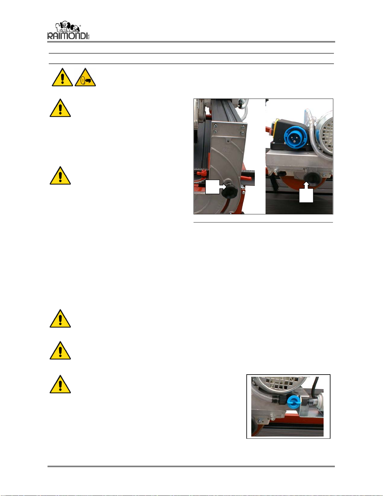
•Drain any water in the tank.
•Loosen the knob under the motor assembly, move the latter to the centre of the slide bar and tighten the
knob again, to balance weight.
•Fold the machine’s legs (the front leg first) and secure the latter in place with the knobs provided.
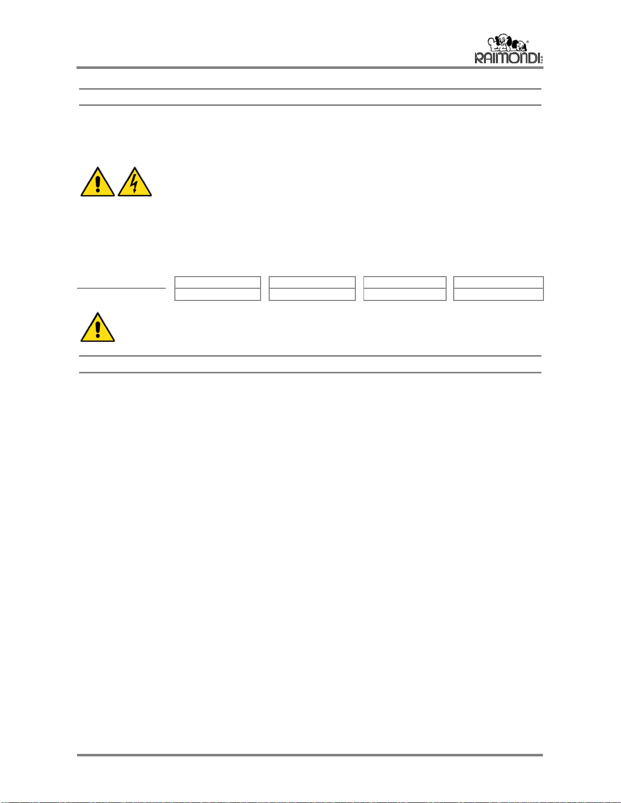
•Before transporting the machine, lift the front and rear sides of the machine.
TWO PEOPLE ARE REQUIRED TO MOVE AND INSTALL THE MACHINE.
TO TRANSPORT THE MACHINE OVER SMALL SPACES, LIFT IT USING THE FRONT HAN-
DLE AND PULL IT FORWARDS WITH THE AID OF THE REAR WHEELS.
FIG.4

ENGLISH PIKUS 105/105DL – PIKUS 75/75DL
7
Electrical Power Supply
;The “PIKUS” saws must be powered at the voltage indicated on the "TECHNICAL DATA" label.
;Always use an effectively grounded cable to hook up the machine. When in doubt, do not plug the
machine in.
;Hook up the machine to a 12A socket.
ATTENTION: THE FOLLOWING PROBLEMS CAN ARISE WHEN USING EXTENSION
CORDS THAT ARE TOO LONG, OR WHEN POWERING THE MACHINE WITH A
VOLTAGE GENERATOR:
•SLOW MOTOR START-UP CAUSING THE SAFETY DEVICES TO CUT IN;
•OVERHEATING OF THE MOTOR WITH A DROP IN POWER;
•ON/OFF DEVICE DOES NOT WORK.
The "PIKUS" saws must be hooked up to a power supply source equipped with a differential switch or a
class II insulation transformer with the characteristics indicated in the table:
TRANSFORMER 230V~50Hz 1,1kW 230V~60Hz 1,1kW 115V~50Hz 1 kW 115V~60Hz 1 kW
DIFFERENTIAL 8,5A Id 20mA 8,5A Id 20mA 17A Id 20mA 17A Id 20mA
ATTENTION: ALWAYS REMEMBER TO PERIODICALLY CHECK THAT THE DIFFERENTIAL
SWITCHES ARE OPERATING CORRECTLY. THIS CAN BE DONE BY PRESSING THE TEST
BUTTON ON THE FRONT OF THE UNIT.
Checks before use
Before using the machine, check for any broken, worn or damaged parts and replace them immediately.
For spare parts and accessories, always follow the instructions in this manual.
Use only original spare parts.
For the best performance and utmost safety, always keep the machine clean and lubricated.
Always unwind the power supply cord completely and check it for damage.
Carefully check the "TECHNICAL DATA LABEL" before plugging in the machine.
If an extension cord is used, make certain that the section is 3x2.5 mm2or greater.
Work on a flat and clean surface, which is clear of hindrances.

PIKUS 105/105DL – PIKUS 75/75DL ENGLISH
8
Assembling/Disassembling the machine
BEFORE PERFORMING ANY OPERATION, MAKE SURE THAT THE MACHINE IS
UNPLUGGED.
TWO PERSONS ARE NEEDED TO ASSEMBLE THE MACHINE
Assembly:
•Take the machine off the pallet and check for
broken or damaged parts.
•Unscrew the two knobs (A) from the rear feet,
namely the feet featuring wheels;
•Whilst one operator raises the rear side of the
machine, the other should pull down the feet and
fasten them with the knobs provided for this
purpose (A);
•Repeat the above steps for the front side of the
machine.
Disassembly:
•Repeat the above operations in reverse order
(first the front section, then the rear).
Water supply
Pour clean water into the machine’s tank until the pump is entirely immersed in the cooling
circuit.
Regulating cut depth
BEFORE PERFORMING ANY OPERATION, MAKE SURE THAT THE MACHINE IS
UNPLUGGED.
The PIKUS machine can be used as follows:
•With the motor assembly locked in place at the
desired cutting depth, tightening the handle (D).
•Manually lowering the motor assembly using grip
(E) (knob (D) loosened).
When performing cuts on material longer than 90 cm
for the 105/105DL version and 60 cm for the
75/75DL version, proceed as follows:
•Release the motor assembly by slackening the
knob (D), so that the disk is in its top-most
position, then move it to its rear stroke end.
•Position the piece to be cut on the table.
•Press the start button and wait until the cooling
water reaches the disk.
•Using the grip, slowly lower the motor assembly
so that the disk enters the material. Lock the
motor assembly in place by tightening the knob
(D)
•The machine is now ready to cut (see Cutting).
ATTENTION: WHEN MAKING PARTICULARLY THICK CUTS, IT IS BEST TO PASS OVER THE
MATERIAL AS MANY TIMES AS REQUESTED BY ITS HARDNESS.
FIG.5
FIG.6
E
D
A
A

ENGLISH PIKUS 105/105DL – PIKUS 75/75DL
9
Positioning the square
BEFORE PERFORMING ANY OPERATION, MAKE SURE THAT THE MACHINE IS
UNPLUGGED.
ATTENTION: CHECK THAT THE SQUARE (A) IS RESTING ON THE BLOCK (H) AND THAT
THE LEVER (C) IS LOCKED.
NORMAL CUTS
•Set the tile on the square (A) and on the rest (B).
NOTE: TO ENSURE A PERFECTLY
SQUARE CUT, REST THE TILE PRE-
CISELY AGAINST THE SQUARE (A).
•Position the indicator on triangle (G) at the
requested measure and lock it with the lever (D).
NOTE: IF THE CUT IS NOT PARALLEL:
- Make sure the square (A) and the rest
(B) are aligned;
- Adjust the position of the square (A)
by turning the adjustment screw (F).
DIAGONAL CUTS
•Loosen the knob (C) and position the square at
45°.
•Loosen the lever (D) and position the indicator
(G) on the triangle (E), namely on the
DIAGONAL tile measurement. Tighten levers (C)
and (D).
Keeping the diamond disk above the surface of
the tile, run the motor assembly and adjust its
position so that, at the beginning and end of the
cut, the diamond disk lines up with the corners of
the tile.
•Reposition the triangle in the correct position and
tighten the lever (D).
NOTE: WHEN CUTTING AT ANGLES OTHER THAN 90° AND 45°, TRACE THE CUTTING
LINE ON THE TILE.
WITH THE MOTOR OFF, PLACE THE TILE ON THE MACHINE TABLE.
LET THE DISK RUN OVER THE TILE AND MAKE SURE THE CUTTING LINE CORRE-
SPONDS TO THE LINE PREVIOUSLY TRACED ON THE TILE. MOVE THE SQUARE
AGAINST THE TILE EDGE AND LOCK IT IN PLACE WITH THE LEVER (C).
FIG.7
FIG.8
D
E
C
A
F
C
E
G
B
D
G
H

PIKUS 105/105DL – PIKUS 75/75DL ENGLISH
10
Cutting
BEFORE TURNING ON THE MACHINE, ADJUST THE DISK GUARD SO THAT IT IS
TOUCHING THE TILE TO CUT AND TIGHTEN THE ADJUSTMENT KNOB
IMPORTANT: BEFORE CUTTING,
MAKE CERTAIN THAT THE COLUMN
LOCK (A) AND THE MOTOR HOIST
KNOBS (B) ARE FIRMLY TIGHTENED.
To prevent bending or warping the disk and
overloading the motor, the motor assembly forward
speed during the cut must be proportional to the
hardness of the material to be cut.
ATTENTION: WHEN MAKING PAR-
TICULARLY THICK CUTS (MAX
80/70mm), IT IS BEST TO PASS OVER
THE MATERIAL SEVERAL TIMES AS
REQUESTED BY ITS HARDNESS.
•Press the start button.
•Wait until the cooling water reaches the diamond
disk.
•Proceed with cutting, slowly bringing the diamond disk up against the material to
be cut.
•Continue cutting keeping the forward speed steady.
•Towards the end of the cut, reduce speed.
If the end of the tile (the last centimeter) breaks, sharpen the diamond disk.
If this does not eliminate the problem, it can be resolved as follows:
•make a 2 cm cut at one end of the tile.
•then turn the tile and make a cut running all the way to the previous 2 cm cut.
IMPORTANT: WHEN CUTTING, BEAR IN MIND THE INSTRUCTIONS GIVEN IN THE
“WORKSTATION” PARAGRAPH (PAGE 4)
MAKE SURE THERE IS ENOUGH CLEAN WATER IN THE TANK TO ENTIRELY COVER
THE PUMP.
DIRTY WATER CAN LEAD TO IMPROPER OPERATION OR EVEN THE BREAKAGE OF
THE PUMP.
USE THE TAP PROVIDED TO ADJUST THE FLOW OF
WATER DELIVERED TO THE DISK.
FIG.9
AD

ENGLISH PIKUS 105/105DL – PIKUS 75/75DL
11
Jolly 45° Operation
BEFORE PERFORMING ANY OPERATION, MAKE SURE THAT THE MACHINE IS
UNPLUGGED.
As far as the DeLux version is concerned,
remove the tile-holder device from the left-hand
side of the machine, by means of the wing nuts,
and fix it to the right-hand side; tighten the wing
nuts after adjusting.
•Loosen the column lock knobs (A) (front and
back), tip the guide bar all the way and lock it by
firmly tightening the column lock knobs.
•Position the motor head so that the diamond strip
is flush with the work surface.
IMPORTANT: BEFORE CUTTING, MAKE
CERTAIN THAT THE COLUMN LOCK (A)
AND THE MOTOR HOIST (B) KNOBS
ARE FIRMLY TIGHTENED.
ATTENTION: BEFORE TIPPING THE
SLIDE BAR, MAKE CERTAIN THAT THE
DIAMOND DISK DOES NOT TOUCH ANY
PARTS OF THE MACHINE OR THE MA-
TERIAL TO BE ROUNDED OFF.
•Position the tile to be rounded off with the glazed
side facing upwards on the work surface and
make certain that it rests perfectly on Square (C).
•Check that the diamond disk is flush with the
glazed surface.
•Bring the triangle (D) up against the tile and lock
in place with the knob (E).
•Run a Jolly test. Make any fine adjustments by
loosening the lever (E), adjusting and tightening it
again.
To perform the Jolly 45° cut properly, the diamond
disk must be well sharpened; if not properly
sharpened it would bend and the cutting line would
not remain flush with the glazed surface.
If the end of the tile (the last centimeter) breaks,
sharpen the diamond disk.
If this does not eliminate the problem, it can be
resolved as follows:
•if you need to round off on side (F), bevel 2-3 cm
on side (G) of the tile.
•then turn it and round off side (F).
FIG.10
FIG.11
E
FG
A
B
C
D

PIKUS 105/105DL – PIKUS 75/75DL ENGLISH
12
Maintenance
BEFORE PERFORMING ANY OPERATION, MAKE SURE THAT THE MACHINE IS
UNPLUGGED.
CLEANING
ALWAYS CLEAN WITH A DAMP SPONGE. NEVER SPRAY WATER.
KEEP THE SLIDE BAR CLEAN (DO NOT GREASE).
LUBRICATION
REGULARLY GREASE THE CHUCK BEARINGS IN THE POINT OF CONTACT WITH THE DISK
HOLDER FLANGE.
CLEANING THE TANK
•Remove the two half-plates.
•Empty the water from the tank by removing the
plug (A) at the bottom of the former.
•Remove all cutting residues and offcuts from the
tank.
•Carefully clean the pump filter tank.
•Do not use tools when cleaning as this could chip
the paint.
FILLING THE TANK
POUR IN ENOUGH CLEAN WATER TO COVER THE PUMP.
FIG.12
A

ENGLISH PIKUS 105/105DL – PIKUS 75/75DL
13
Replacing the diamond disk
•Remove the plastic spray guard.
•Loosen the screws and remove the disk guard.
•Insert an Allen wrench into the hollow on the
flange-holder shaft.
•Loosen the disk securing nut with the supplied 22
mm Allen wrench, turning it clockwise.
•Install the diamond disk, following the direction of
rotation indicated on the disk and on the disk
guard.
•To ensure that the disk is firmly secured in place,
tap on the shaft of the 22 mm Allen wrench with a
hammer.
•Refit the disk guard.
•Manually rotate the disk to check that it has been
installed correctly.
ATTENTION: DO NOT FORGET TO
REFIT THE SPRAY GUARD.
SHARPENING THE DIAMOND DISK
SHARPEN THE DIAMOND DISK BY RUNNING A FEW CUTS AGAINST THE DISK
SHARPENER.
Regulating the slide device
Set the motor head to its low position.
If the motor head shows excessive play, proceed as
follows:
•Loosen the nut (A).
•Adjust by means of the screw (B).
•Tighten the nut (A).
FIG.13
FIG.14
B
A

PIKUS 105/105DL – PIKUS 75/75DL ENGLISH
14
Repairs
BEFORE PERFORMING ANY OPERATION, MAKE SURE THAT THE MACHINE IS
UNPLUGGED AND EMPTY THE TANK.
REPLACING THE PUMP
•Remove the table (A).
•Empty the tank.
•Loosen the wing nut (B) and remove the pump.
•Open the terminal block cover of the main electric
motor.
•Unplug the pump power supply cable.
•Pull the cable out of its sheath.
•Disconnect the water drainage hose.
•Replace the damaged pump with a new one, fit
the cable into its sheath and restore connections.
•Close the terminal box cover being careful not to
pinch the cables and correctly position the
rubber gasket.
•Reconnect the pump water drainage hose to the
pump.
•Fasten the pump (A) in place by tightening the
wing nut (B).
Replacing the starter
BEFORE PERFORMING ANY OPERA-
TION, MAKE SURE THAT THE MA-
CHINE IS UNPLUGGED.
•Open the terminal block cover of the main electric
motor.
•Disconnect the wire coming from the starter.
•Loosen the screws that secure the starter (A) to
the machine and replace the starter.
•Tighten the screws which were previously
loosened.
•Resume the connections to the motor.
•Close the terminal block cover, being careful not
to pinch the cables and correctly position the
rubber gasket.
Replacing the switch and/or thermal switch
BEFORE PERFORMING ANY OPERATION, MAKE SURE THAT THE MACHINE IS
UNPLUGGED.
•Loosen the two screws (B).
•Remove the switch.
•Disconnect the cables.
•Replace the switch or thermal switch.
•Reconnect the cables.
•Tighten with the appropriate screws.
FIG.15
FIG.16
B
A
A
B

ENGLISH PIKUS 105/105DL – PIKUS 75/75DL
15
Disposal
WHEN THE MACHINE, OR PARTS, ARE TO BE DEMOLISHED, FOLLOW THE INDICATIONS
OUTLINED IN THE CURRENT LEGISLATION.
SWITCH HOLDER ABS "ABS"
MACHINE BODY STEEL "AC"
ALUMINIUM "AL"
POLYAMIDE "PA"
DISK GUARD
SLIDE BAR
COLUMN SQUARES
HALF-PLATES
ALUMINIUM "AL"
MOTOR COPPER "CU"
ALUMINIUM "AL"
STEEL "AC"

PIKUS 105/105DL – PIKUS 75/75DL ENGLISH
16

ENGLISH PIKUS 105/105DL – PIKUS 75/75DL
17
POS. CODE PART NAME
1 423BL75
423BL105 TILE HOLDER DEVICE (PIKUS 75)
TILE HOLDER DEVICE (PIKUS 105)
1\1 423AST75
423AST105 CLAMPING ROD (PIKUS 75)
CLAMPING ROD (PIKUS 105)
1\2 423PBLPS TILE HOLDER DEVICE SUPPORT
1\3 423PBLPL TILE HOLDER DEVICE SUPPORT
1\4 423MANSNO CONNECTING ROD FOR ARTICULATION
1\5 306MA01D HANDKNOB
1\6 310BS07D BUSHING, O.D.19
1\7 314TO04D TORS. SPRING F2.5
1\8 322QU01C PLUG, 20X20
1\9 354CAT022 RUBBER STRIP LL570 (PIKUS 75)
RUBBER STRIP LL870 (PIKUS 105)
2 154SE05D MOTOR TRANSPORT HANDLE
3 192SQ01A COMPLETE TRIANGULAR SQUARE
3\1 305MR06C HANDLE
3\2 191TL03D TRIANGULAR SQUARE
3\3 191PE01D SQUARE HOLDER SLIDER
4 235ZS01A
235ZS02A STARTER 230V 50/60HZ
STARTER 110V 50/60HZ
4\1 234MD01C
234MD02C
234MD04C
MICRO CIRCUIT BREAKER 16A 230V 50/60HZ
MICRO CIRCUIT BREAKER 16A 110V 50HZ
MICRO CIRCUIT BREAKER 16A 110V 60HZ
4\2 234TR04C THERMAL SWITCH, 211 15A 230V 50/60HZ
4\3 246PM03D MICROCIRCUITBREAKERHOLDER,2PCS
5 240
240110 IMM. PUMP 230V.50/60HZ
IMM. PUMP 110V.50/60HZ
6 263PE01A SPRAY GUARD
7 264PV04C MOBILE SOCKET
8 268MC01D MOTOR BLOCK
9 297IN25D
297IN26D INDUCTION MOTOR 1.1kW 230V 50/60HZ
INDUCTION MOTOR 1.1kW 110V 50/60HZ
9\1 303VM06C FAN
9\2 2872501C CAPACITOR
9\3 3047101C FAN COVER
10 309CS01A SHEAVE WITH BEARINGS
11 311RB03D LEG WITHOUT WHEEL HOLDER
12 311RB02D LEG WITH WHEEL HOLDER
13 325VP10D
325VP15D TANK FRAME (PIKUS 75)
TANK FRAME (PIKUS 105)
14 320PG03C SHEATH TERMINAL
15 156BS02A LH FENCE
15\1 423LEVAA LEVER (A)
15\2 423CERSX LH HINGE
15\3 156RB02D LH SWINGING GRID
15\4 423LEVAB LEVER (B)
16 156BS02D RH FENCE
16\1 423LEVAA LEVER (A)
16\2 423CERDX RH HINGE
16\3 156RB01D RH SWINGING GRID
16\4 423LEVAB LEVER (B)
17 423AS+RON LOCKING PIN
18 263FE07D MOBILE DISK GUARD
19 114RE09D
114RE10D GUIDE (PIKUS 75)
GUIDE (PIKUS 105)
20 156NL09D
156NL10D AL. GRID (PIKUS 75)
AL. GRID (PIKUS 105)
21 158GB02D RING NUT, Ø75
POS. CODE PART NAME
22 179CC250Q DIAMOND DISK, Ø250 F25.4 SMOOTH CROWN
23 191GE02D GUIDE FOR SQUARE, LL450mm
24 191AE04D SQUARE FOR SUPPORT, LL216mm
25 251RE05D ALUMINIUM COLUMN
26 262PO02D DISK COVER, COVER Ø200 Ø250
27 262CO05D DISK COVER, DOOR Ø200/250
28 265LM01D CASING ON MOTOR SIDE
29 265LD01D CASING ON DISK SIDE
30 278PA01D DISK HOLDER FLANGE
31 278PB01D DISK FIXING FLANGE
32 286PV02C POLY-V BELT
33 292VA06D PULLEY, Ø48
34 292VA05D PULLEY, Ø34
35 293PM02D MOTOR SUPPORT
36 294PC03D SHEAVE HOLDER
37 305PF06 FEM. KNOB, Ø40 8MA
38 305PF15C FEM. KNOB, Ø60 8MA
39 305MR06C HANDLE, 8MAX25
40 305PM35C MALE KNOB, Ø60 10MAX40
41 305PF12C FEM. KNOB, Ø40 6MA
42 306MA01D HANDKNOB
43 3081503C BEARING, 6202 ZZ
44 310BS12D BUSHING, O.D.14
45 310BE01D BUSHING, CH17
46 314AN02D CABLE-CARRYING SPRING
47 314TO02D TORS. SPRING, ØF3.8
48 314TO03D TORS. SPRING, ØF2.5
49 315CB10C WHEEL, Ø125
50 320PA02C CORE HITCH Ø50
51 322CN03C TAPERED PLUG
52 322QU01C PLUG, 20X20
53 322RE04C PLUG, 60X20
54 324RU01C TAP
55 324DE01C DEVIATOR
56 903TERRA EARTH LABEL
57 218PPOMPA PUMP HOLDER
58 423ASTRIN DISK COVER TRANSMISSION ROD
59 423PASOLA PLATE WITH SLOTS
60 900CH6X15 TAB, 6X6X15
61 423ALBPDS DISK HOLDER SHAFT
62 900RORA10 SHIM, Ø105
63 900RORA56 SHIM, Ø56
64 900ANCO55 COMPENSATION RING, Ø54.8
65 423OR SEAL, 22 X 32 X 7
66 423REGSQU SQUARE ADJUSTER
67 420LETTOR DEGREE INDICATOR/SQUARE
68 420MM SCALED ADHESIVE LABEL FOR SQUARE
69 903PIKUS NAMEPLATE
70 423PRUBIN TAP SUPPORT PLATE
71 192SQ03A COMPLETE FIXED SQUARE ASSEMBLY
71\1 191PE01D SQUARE HOLDER, LL55mm
71\2 305MR06C HANDLE
71\3 191SF05D FIXED SQUARE
72 323BR03C SETSCREW, SIZE 5
73 323CH12C WRENCH, SIZE 22
74 288 WHITE SHARPENING STONE
75 158GB03D SELF-LOCKING RING
76 374MM SCALED ROD, LL520mm

PIKUS 105/105DL – PIKUS 75/75DL ENGLISH
18
230 V ∼50 Hz 230 V ∼60 Hz 115 V ∼50 Hz 115 V ∼60 Hz
A 3G 1,5 H 07 RNF A 3G 1,5 H 07 RNF A3G 2,5 H 07 RNF A 3G 2,5 H 07 RNF
B 15 A B 15 A B22 A B 22 A
C F 1 A C F 1 A CF 2 A C F 2 A
D SINGLE-PHASE
230V ∼50Hz 1,1kW
8,5A 2800 min-1
MOTOR CLASS F
D SINGLE-PHASE
230V ∼60Hz 1,1kW
8,5A 3360 min-1
MOTOR CLASS F
DSINGLE-PHASE
115V ∼50Hz 1kW
17A 2800 min-1
MOTOR CLASS F
D SINGLE-PHASE
115V ∼60Hz 1kW
17A 3360 min-1
MOTOR CLASS F
E 16 μF 400 VL E 16 μF 230 VL E32 μF 115 VL E 32 μF 115 VL
F 230 ∼50 Hz 13 W
0,84 A 2800 n-1 F 230 ∼60 Hz 13 W
0,84 A 3360 n-1 F115 ∼50 Hz 13 W
1,6 A 2800 n-1 F 115 ∼60 Hz 13 W
0,84 A 3360 n-1


PIKUS
PIKUS
Date of manufacture
Serial n°
RAIMONDI S.p.A MODENA
2003 developed by TECNO DINAMICA S.n.c.
This manual suits for next models
3
Table of contents
Other RAIMONDI Saw manuals