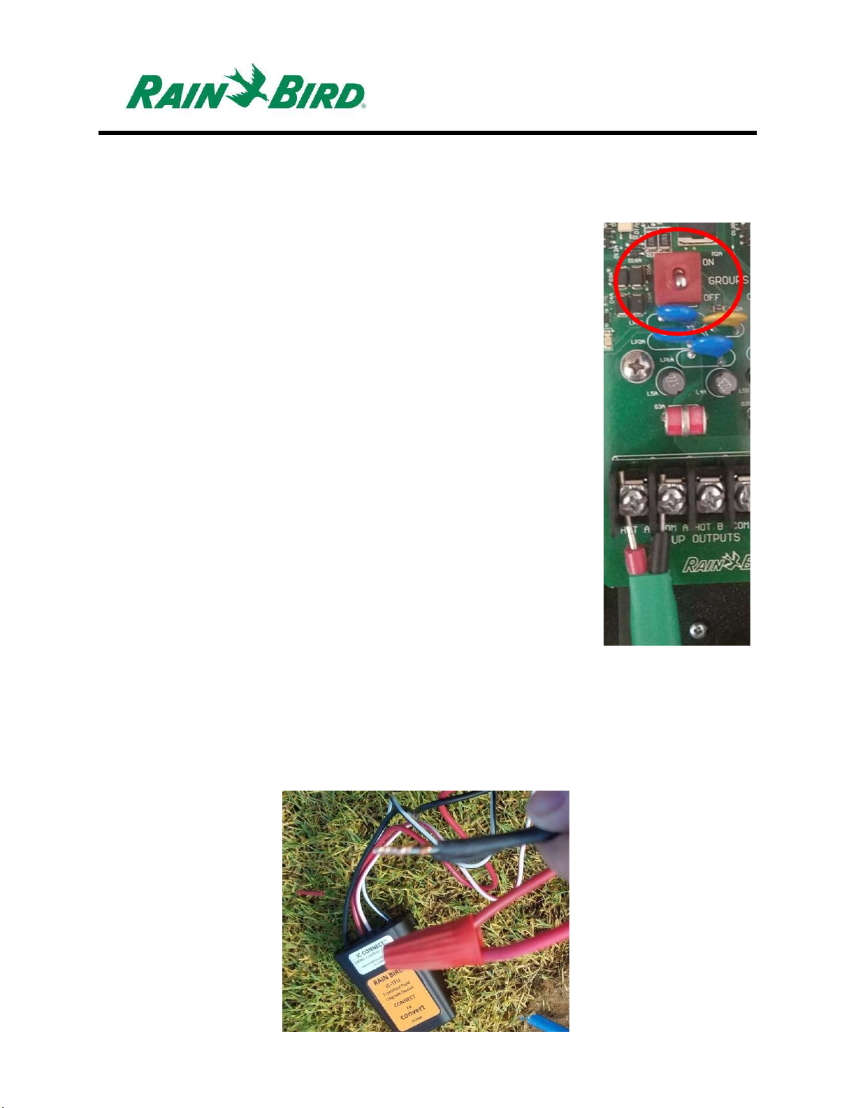
Installation Step #2 – Connect to MAXI™ wire
1. Assure the IC wire path that the IC-TFU will be connected to is
powered OFF. (Figure 4)
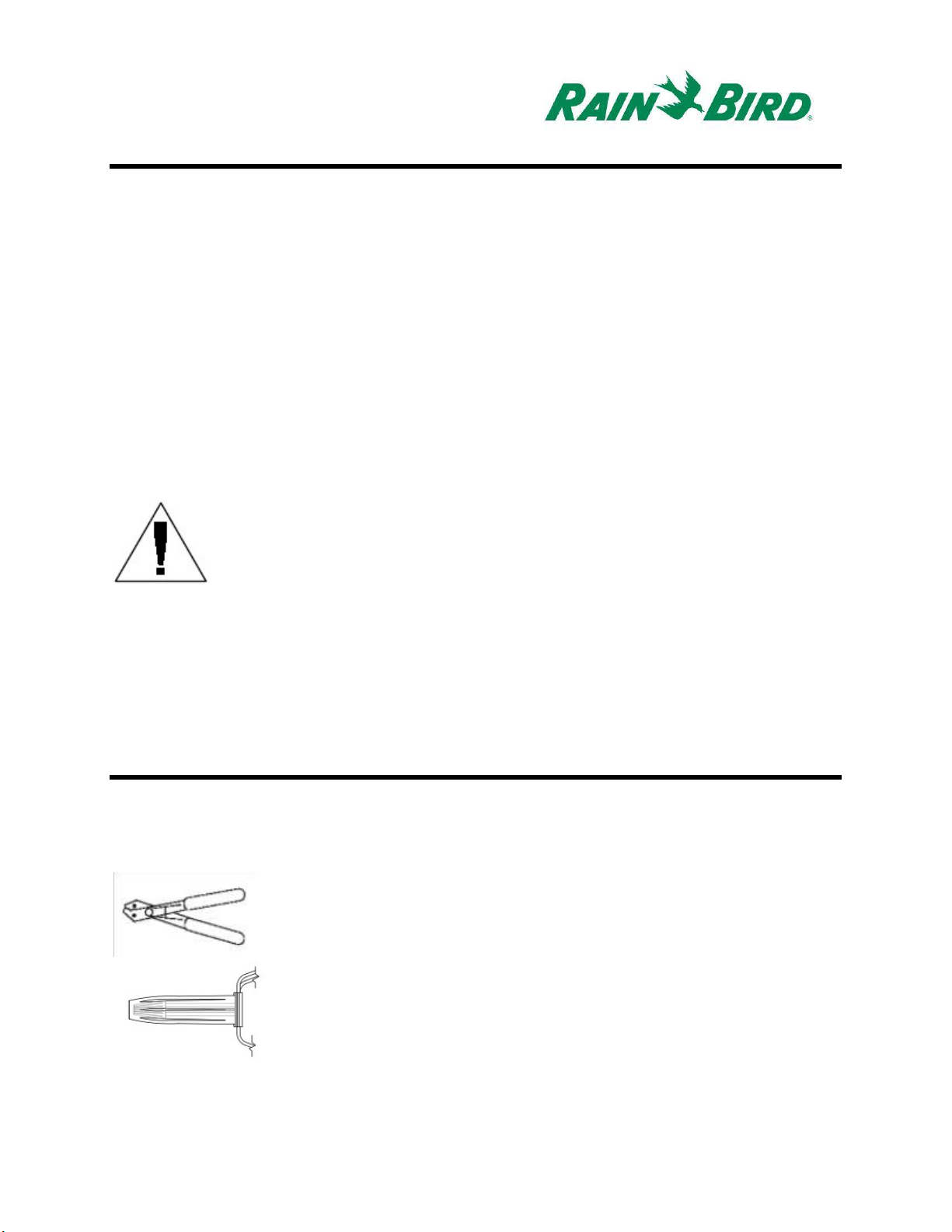
2. IC-TFU should arrive from the factory with wire ends stripped.
If not, strip approximately 1” of insulation from each wire.
Take care not to score the copper strands.
3. Strip approximately 1” of insulation from each MAXI™ wire (IC
SystemTM field wiring) to be spliced with IC-TFU. Take care not
to score copper conductor.
4. Splice / join wires by wrapping IC-TFU wires around MAXI
wires. (Figure 5)
a. Connect the IC-TFU (red) wire to the MAXI™ (red)
wire. The IC-TFU to MAXI™ connection should be
solid red on both sides of the splice.
b. Connect the IC-TFU (black) wire to the MAXI™
(black) wire. The IC-TFU to MAXI™ connection
should be solid black on both sides of the splice.
c. Trim joined wires to appropriate length for the wire
nuts.
Figure 4
Figure 5