Rain Bird Gold LINK 900 User manual

Rev 1.0 September 2015
Golf LINK900
OWNERS
MANUAL

1
September 2015
Contents
1.
Introduction..............................................................................................................................................................2
2.
Components .............................................................................................................................................................3
3.
Radio Basics .............................................................................................................................................................4
a)
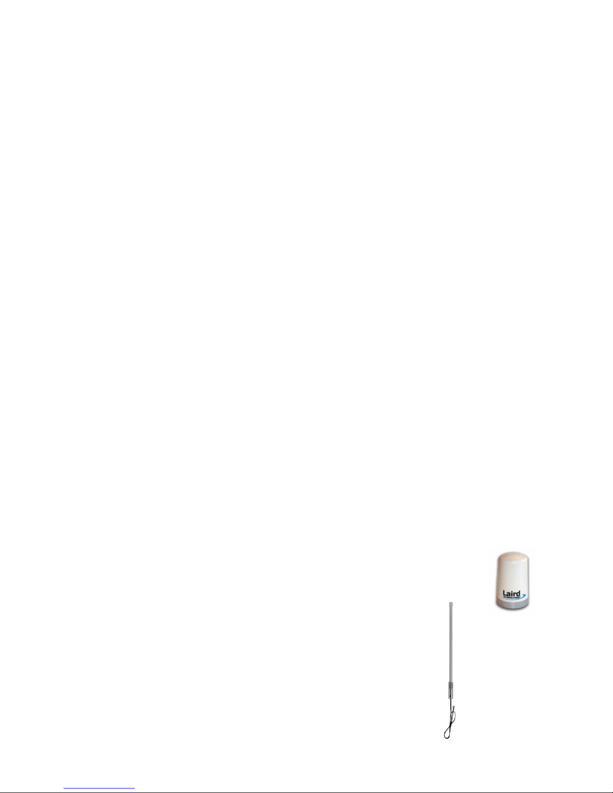
Antennas: ............................................................................................................................................................4
b)
Antenna Fie d Patterns: .....................................................................................................................................5
c)
Antenna Cab es: .................................................................................................................................................6
d)
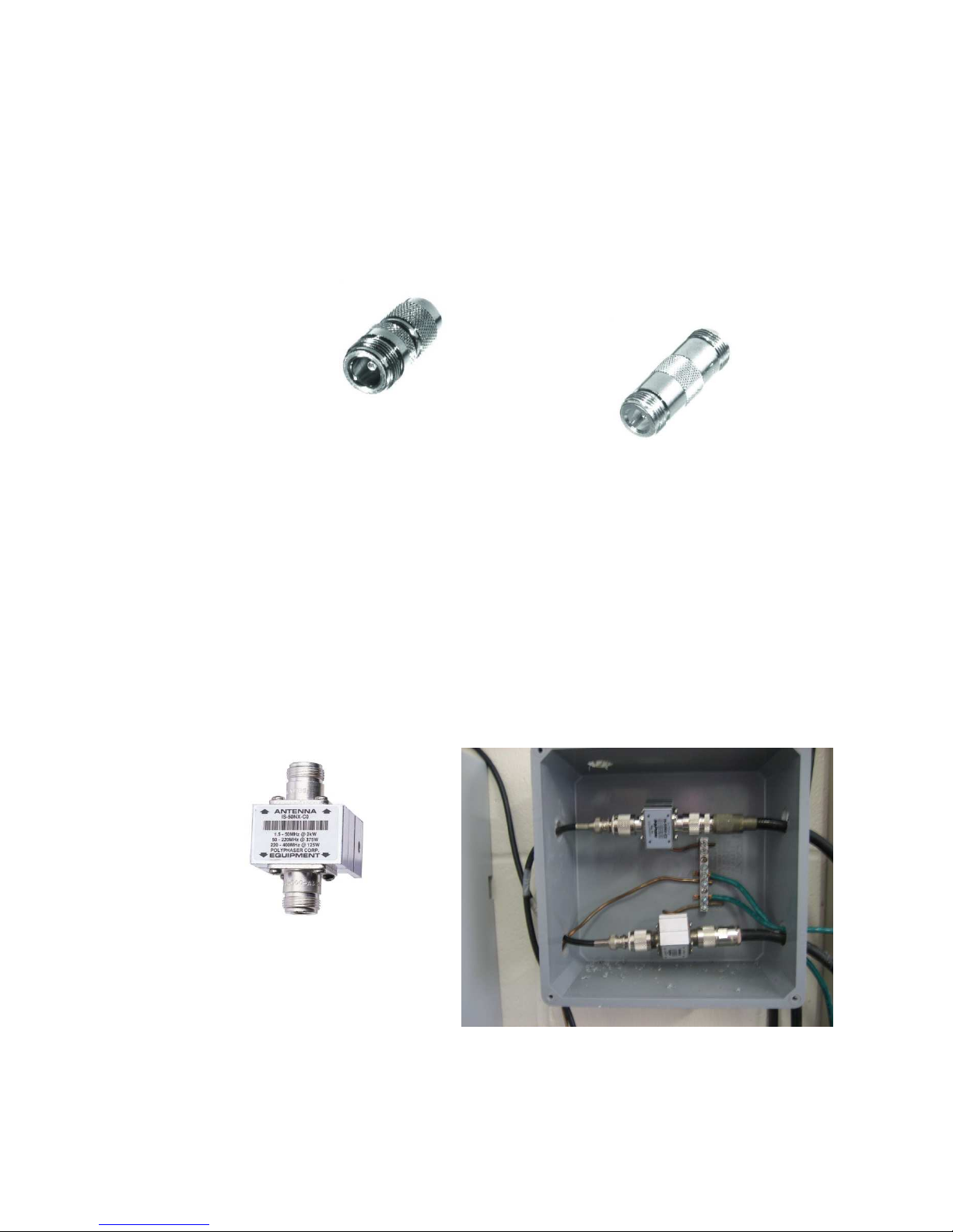
Antenna Cab e Connectors................................................................................................................................6
e)
Adapters: .............................................................................................................................................................7
e)
Surge Protection:................................................................................................................................................7
4.
Component Setup....................................................................................................................................................8
a)
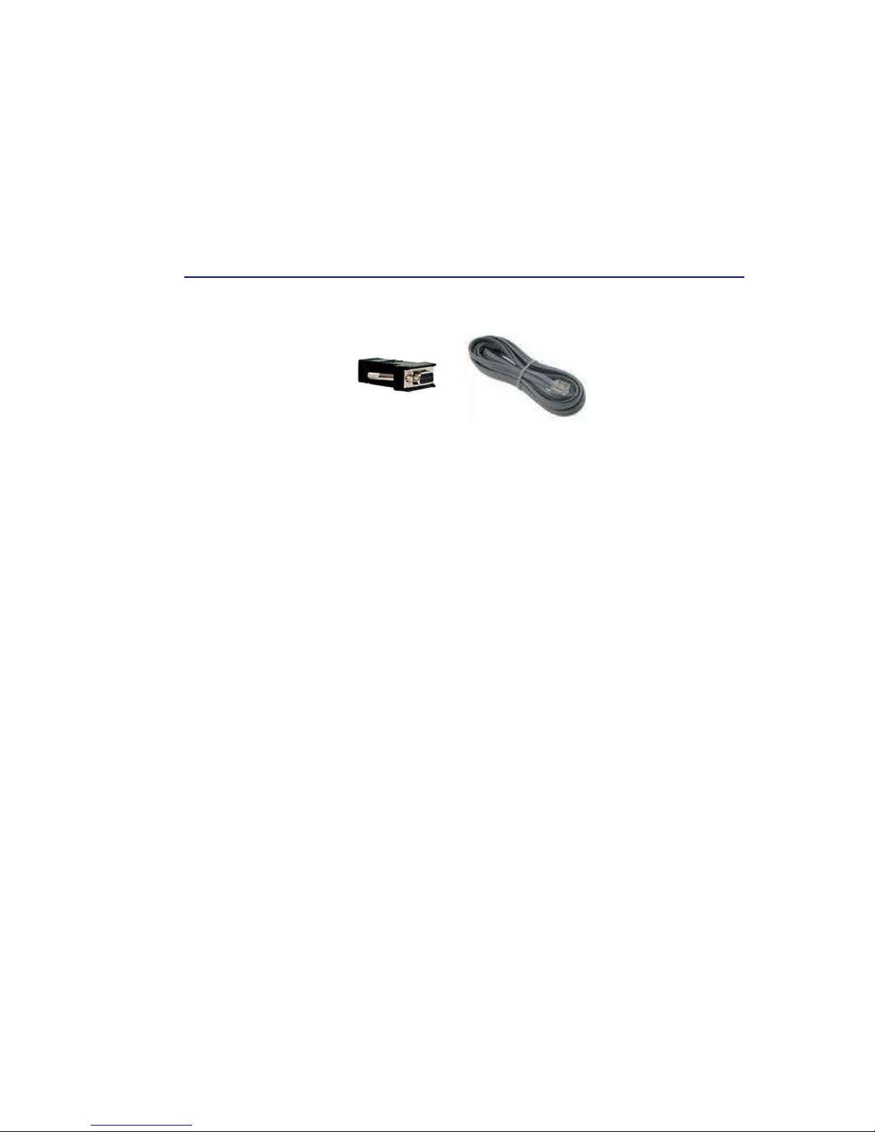
MIM-LINK / TWI-LINK Interface Connection to Centra Contro .................................................................8
1.
Direct Connect ................................................................................................................................................8
2.
Connection via MAXI
®
Remote Location Kit (MRLK).................................................................................8
b)
LINK900 radio for MIM-LINK / TWI-LINK Insta ation & Programming......................................................8
c)
LINK900 radio for fie d contro ers Insta ation & Programming................................................................12
d)
Programming the PAR+ES Contro er............................................................................................................18
e)
Using Sensors on a Go f LINK900 system.....................................................................................................18
5.
Operation
........................................................................................................................................................22
6.
Troub eshooting
..........................................................................................................................................24
a)
Link Diagnostic screen .....................................................................................................................................24
1.
Basic Troub eshooting .................................................................................................................................25
2.
MIM / TWI Troub eshooting .......................................................................................................................26
3.
PAR+ES Contro er Troub eshooting..........................................................................................................26
7.
Appendix
.........................................................................................................................................................29
a)
Sensors on the LINK900 system ....................................................................................................................29
b)
Changing the COM port used by a USB-to-Seria Adapter .........................................................................33

2
September 2015
1. Introduction
Congratu ations on purchasing a Rain Bird
®
irrigation system with LINK900 advanced wire ess
communication techno ogy. LINK900 advanced wire ess communication techno ogy wi provide you with
robust communication between your Rain Bird
®
Go f Centra Contro MIM-LINK or TWI-LINK interface and
fie d contro ers for many years.
The LINK900 system uses custom designed Frequency Hopping Spread Spectrum (FHSS) radios.
•Rapid y hops through 128 frequencies between 902-928 MHz
•High y resistant to narrowband interference
•Operating range of -40ºF (-40ºC) to 158ºF (70ºC)
•Signa can be repeated from one contro er to the next
•Uses Digita techno ogy
•No antenna height restriction in most areas

3
September 2015
2. Components
Here are the main components needed for a Rain Bird
®
irrigation system with LINK900 wire ess
communications:
Centra Contro computer:
Interface(s):
MAXI
®
Interface Modu e (MIM-LINK) or Two-Wire Interface (TWI-LINK)
LINK900 radios:
PAR+ES (LINK) contro ers:
Standa one Repeater (optiona ):

4
September 2015
3. Radio Basics
LINK900 wire ess communication works by broadcasting radio waves to communicate between the centra
contro and fie d contro ers. The LINK900 system uses custom designed Frequency Hopping Spread
Spectrum radios (FHSS).
Key Advantages:
-No FCC icense required for operation in USA.
-No antenna height restriction in most areas (check oca regu ations)
-Capabi ity to use fie d contro er radios as repeaters to re ay the signa
-FHSS is high y resistant to narrowband interference
-FHSS is difficu t to intercept
-FHSS can coexist in a frequency band with other broadcasts with minima interference
Signa strength is measured in decibe s (dB). Radios transmit with a certain amount of power (Wattage) and
signa reception is subject to oss of strength due to attenuation caused by impedance in the antenna
cab es, fittings, and the atmosphere itse f.
Radio transmission power is re ated to signa strength in the fo owing manner:
-Reducing the output wattage by ha f reduces the signa strength by 3dB
-Doub ing the output wattage increases the signa strength by 3dB
In Rain Bird
®
LINK900 wire ess communications, no true e ectronic signa boost is provided after the radios.
Antennas can be used to shape or focus more of the transmitted signa energy into the areas targeted. This
signa increase is termed as “Gain”. An antenna with a “dB gain” va ue does not provide more power, but
rather it modifies the shape of the transmitted signa . The higher the antenna gain, the narrower the usefu
signa beam width.
a)
Antennas:
Rain Bird
®
LINK900 wire ess communications uses two distinct types of vertica y po arized
antennas. Omnidirectiona and Directiona (a so known as Yagi).
Omni-directional:
This is the most common antenna used. Each Rain Bird
®
Go f LINK900 radio/modem/antenna kit
(H49008 & H49004) comes with this type of antenna. Different types of Omni-directiona
antennas can be used on a LINK900 system.
Here are two examp es:
Standard PAR+ES Omni “shot g ass sty e” antenna, 3dB (GSP-TRA9023N)
High Gain 48” Omni antenna, 5dB (GSP-ODA-48)

5
September 2015
Directional Antenna (Yagi :
The Yagi antenna is typica y used to focus the signa towards a sing e point and to minimize
interference to and from other radios.
Yagi Antenna, 6dB (GSP-YAGI-6)
b)
Antenna Fie d Patterns:
Each type of antenna has a defined fie d pattern. This indicates how the radio waves are
transmitted from and received by the antenna. The fo owing are examp es of two common types
of patterns; Omni-directiona and Yagi.
Omni-directiona Antenna Fie d Pattern (Typica )
Yagi Antenna Fie d Pattern (Typica )

6
September 2015
c)
Antenna Cab es:
Cab e se ection is very important as too much signa oss can affect the overa communication
performance. In genera , ower oss cab es tend to be arger in diameter and ess f exib e. LMR
type cab es are more weather resistant than RG type cab es, but RG type cab es tend to be much
more f exib e. Here is a tab e showing examp es of signa oss in dB based on the type of cab e:
On y 50 Ohm cab e may be used with LINK900 systems. P ease note that the frequency being
used wi a so affect the cab e oss. Norma y, higher frequencies have a higher oss potentia .
This tab e is for the 900MHz range of frequencies.
d)
Antenna Cab e Connectors
There are a wide variety of cab e terminations avai ab e for 50 Ohm antenna cab e. Four
different cab e terminations are common in LINK900 systems: N, TNC, SMA and NMO. Other
terminations may a so be encountered, especia y if custom antennas or other devices are used.

7
September 2015
e)
Adapters:
In some cases, adapters may be required to accommodate the different antenna and cab e
terminations used. However, the use of adapters shou d be minimized, as each adapter causes a
signa oss of ~0.25dB. Rain Bird recommends using cab es made with the proper connector
types to minimize the use of adapters. The LINK900 radio is terminated with an SMA Fema e
connector and requires an SMA Ma e cab e end connection. The Standa one Repeater is
terminated with a TNC Fema e connector and requires a TNC Ma e cab e end connection. Here
are some adapter examp es
e)
Surge Protection:
Surge protection shou d be used on a externa antenna insta ations such as at the MIM-LINK /
TWI-LINK centra contro interface. There is no need for surge protection at a fie d contro er
ocation if the standard antenna inc uded in the Rain Bird
®
LINK900 radio/modem/antenna kits
(H49008 & H49004) is used. Where used, the surge protection MUST be rated for 900MHz
operation and MUST be grounded with a bare copper wire and a ground rod or p ate. Rain Bird
recommends the Rain Bird
®
Po yphaser (HA1100) for surge protection of externa antenna
insta ations in LINK900 systems.
Adapter, TNC Male to N-Female
Barrel Adapter, N-Female to N-Female
Rain Bird
®
Polyphaser (HA1100
N-Female by N-Female
Two Polyphaser setup with proper grounding

8
September 2015
4. Component Setup
Proper insta ation of a components is key to having a robust system. This section wi cover in detai a the
steps needed to proper y setup LINK900 wire ess communication for your Rain Bird
®
Go f irrigation system.
a)
MIM-LINK / TWI-LINK Interface Connection to Centra Contro
There are two options for connecting the centra contro interface (MIM-Link or TWI-Link) to the
centra contro computer: direct seria connection or via a MAXI
®
Remote Location Kit.
1. Direct Connect
For the direct connection when the interface is ocated near the centra computer, just
connect the interface to the computer using the supp ied cab e.
2. Connection via MAXI
®
Remote Location Kit (MRLK)
When the interface is remote y ocated away from the centra computer, a MAXI
®
Remote Location Kit (p/n HA1000) is required.
b)
LINK900 radio for MIM-LINK / TWI-LINK Insta ation & Programming
To insta the LINK900 radio/modem kit (H49001) in the MIM-LINK / TWI-LINK interface, on y
two cab es need to be connected. A 9-pin seria ribbon cab e connects the LINK900 radio and the
Output Board ocated in the back of the interface. The second cab e is the antenna cab e (SMA
connector) which must be connected to an externa antenna (not inc uded in H49001).
Ribbon cab e
Antenna cab e
The pictures above show two different ways to mount the LINK900 radio inside the interface.

9
September 2015
Programming:
The LINK900 radios supp ied with H49001, H49004, and H49008 are identica and
interchangeab e. However, the programming in them wi vary depending on the function of the
radio. The LINK900 radio ocated at the MIM / TWI wi a ways be programmed as the Master
(M) radio.
LINK900 radios are programmed using the GE MDS E ement Manager app ication which runs on
Microsoft Windows
OS computers. The software can be down oaded at this address:
https://www.gedigita energy.com/communications/MDS/software.asp?directory=Too box
The programming cab e (GSP-MDS-PRGCBL) is a so needed, which is composed of a proprietary
cab e and 9-Pin to RJ-11 adapter.
Connect the cab e to the radio using the RJ-11 connector and connect the seria adapter to the
computer. P ease note that if the computer does not have a seria port and a USB-to-Seria
adapter is used, the COM port used by the adapter must be se ected in MDS E ement Manager.
See Appendix section “7b” for he p.
WARNING:
A ways ensure that an antenna is connected to the LINK900 radio before the radio
is powered-up, or damage to the radio may occur.
The LINK900 radio must be powered before a connection can be estab ished. The radio receives
power from the MIM/TWI via the 9 pin ribbon cab e. Programming the radio is comp eted via
the Configuration menu in the GE MDS E ement Manager app ication.
Start the GE MDS E ement Manager app ication. Confirm Device Type is set to TransNet. Under
Seria Connections, se ect the COM port that the programming cab e is connected to. Confirm
the Settings (9600, 8, N, 1). To connect to the radio, se ect Connect Seria to begin
communicating with the LINK900 radio.

10
September 2015
Upon successfu connection to the LINK900 radio, the Genera Information wi popu ate with the
radio’s Seria Number, Network Address, Firmware Revision Leve and other detai s. This
information may be updated at any time by c icking on the Refresh icon.
Device Type
COM Port
Seria Settings
Connect to LINK900 Radio

11
September 2015
For the Master radio at the MIM-LINK / TWI-LINK, the settings shou d be as fo ows:

12
September 2015
*P ease note that the “Network Address” shown in the Configuration Settings/Network needs to
be the same in a the radios that wi be used by the fie d contro ers. That “Network Address” is
a user definab e 4-digit number. Using the ast 4 digits of the seria number of the Master radio is
recommended. The seria number is shown on the Genera Information of the GE MDS E ement
Manager app ication.
Set the baud rate for the LINK900 radio in the Command Line Mode under the Uti ities menu.
Type “BAUD 600 8N1” and Enter. Confirm the baud rate is set to 600 8N1 by typing “BAUD” and
hitting Enter.
Confirm the Port is set to TTL by typing PORT and hitting Enter. PORT TTL shou d be disp ayed.
If RS232 or RS485 is disp ayed, the radio is not a LINK900 radio.
c)
LINK900 radio for fie d contro ers Insta ation & Programming
The LINK900 radio can be mounted in different ocations, depending on the type of fie d
contro er used. The fo owing examp e is for the PAR+ES contro er. The LINK900 radio inside
the PAR+ES wi connect to the LINK Interface Board and the antenna cab e.
The 9-Pin ribbon cab e connects from the 9-Pin connector on the radio to the 9-Pin connector on
the LINK Interface Board, ocated under the facep ate of the contro er.
Dip switch viewing port
Receptac e for PIB ribbon
cab e
Seria connector of the LINK Interface Board Power cab e connector
The LINK Interface Board must be configured for the Wire Group it wi use to communicate with
the MIM-LINK/TWI-LINK. There are dip switches on the upper right section of the LINK Interface
Board. The first two dip switches are used to set the Group ID*. However, it is recommended to
set the Group ID through the facep ate of the PAR+ES in the “System Information” menu. If the
Group is assigned a va ue of 1, 2, 3, or 4 through the facep ate, it wi override the setting of dip

13
September 2015
switch #1 and #2. It is recommended to never eave the Group at “0” in the System Information
menu.
*P ease refer to Section 5 – Operation for more information on Group settings
A ways ensure that dip switches #3 and #4 are in the “Off” position.
A so ensure that the orange power cab e is connected next to the 9-Pin seria connector on the
LINK Interface Board, and the ribbon cab e from the Power Interconnect Board (PIB) is
connected.
The antenna cab e connects to the SMA connector on the radio. The antenna cab e that is
provided with the LINK900 Radio/Modem/Antenna Kit H49008 wi be routed from the radio to
the enc osure id. For the PAR+ES the standard antenna wi be mounted on the a uminum p ate
that wi be mounted to the enc osure id.
Antenna cab e connection
Programming:
LINK900 radios used in fie d contro ers may be programmed as either a Remote (R) radio or an
Extension (X) radio. A Remote radio may communicate either direct y with the Master (M) radio,
or through one or more Extension radios connected to the Master. In addition to acting as a
Remote radio for the fie d contro er it is insta ed in, an Extension radio a so acts as a repeater,
forwarding data between the Master and other Remote or Extension radios. Fie d contro ers
with radios programmed as an Extension are used to send and receive data to that fie d
contro er, and a so repeat signa s to other radios. The site survey process wi he p determine
which radios shou d be programmed as Remote or Extension.
Programming Remote (R radios:
Remote radios are programmed with the GE MDS E ement Manager uti ity. Fo ow the same steps
as programming the Master radio, but use the fo owing settings:
W
ir
e
Group set by dip switches on
LINK
I
FB:
Group
1 1
o
n
,
2
o
ff
Group 2 1
off,
2
on
Group 3 1
on
,
2
on
Group 4 1
off,
2
o
ff

14
September 2015
For Remote radios at sate ite ocations, the settings shou d be as fo ows:

15
September 2015
Set the baud rate for the LINK900 radio in the Command Line Mode under the Uti ities menu.
Type “BAUD 600 8N1” and Enter. Confirm the baud rate is set to 600 8N1 by typing “BAUD” and
hitting Enter.
Confirm the Port is set to TTL by typing PORT and hitting Enter. PORT TTL shou d be disp ayed.
If RS232 or RS485 is disp ayed, the radio is not a LINK900 radio.
Note that the “Network Address” shown in the Configuration Settings/Network section needs to
be the same as the address used on the Master radio. The Primary Extension Address setting is
shown here with an XPRI va ue of “0” to receive its commands from the Master. If this Remote
radio needs to be configured to receive its signa from an Extension radio, the Primary Extension
Address (XPRI) va ue shou d match the Extension Address (XADDR) va ue of the Extension radio
re aying the signa . P ease refer to Figure A.
Figure A
Figure A above depicts the different configurations that can be seen when using the LINK900
radios to transmit the signa from the Master to Remote and Extension radios. Extension radios
repeat the signa on a unique extension address defined by the Extension Address XADDR va ue.
The signa from the Master may be repeated by a maximum of 4 Extension radios before
terminating at a Remote Radio.

16
September 2015
Programming Extension (X radios:
Remote radios are programmed with the GE MDS E ement Manager uti ity. Fo ow the same steps
as programming the Remote radio, but use the settings be ow:

17
September 2015
Set the baud rate for the LINK900 radio in the Command Line Mode under the Uti ities menu.
Type “BAUD 600 8N1” and Enter. Confirm the baud rate is set to 600 8N1 by typing “BAUD” and
hitting Enter.
Confirm the Port is set to TTL by typing PORT and hitting Enter. PORT TTL shou d be disp ayed.
If RS232 or RS485 is disp ayed, the radio is not a LINK900 radio.
Note that the “Network Address” shown in the Configuration Settings/Network section needs to
be the same as the address used on the Master radio. The Extension Address (in ight green) for
each Extension radio must be programmed with a unique (XADDR) va ue between 1 and 31.
The Primary Extension Address (XPRI) setting (in ye ow) is shown here with an XPRI va ue of
“0” to receive its commands from the Master. If this Extension radio is to receive its signa from
another Extension radio, the XPRI va ue shou d match the XADDR va ue of the Extension radio
re aying the signa . Refer to Figure A for a visua representation.
If the signa needs to be repeated but there are no fie d contro ers avai ab e to do so, a
Standa one Repeater radio is avai ab e.
The Standa one Repeater radio kit (p/n IQ4630) is programmed as an Extension radio, with the
same settings as mentioned above. P ease note that the Standa one Repeater radio cannot be
used to rep ace the LINK900 radio/modem/antenna kit needed for fie d contro ers.

18
September 2015
d)
Programming the PAR+ES Contro er
The PAR+ES contro er must a so be configured for communication with the centra computer via
the LINK900 radio. A proper y programmed PAR+ES contro er wi :
•Receive contro information from the MIM-LINK in the form of START and STOP
commands. This wi activate or deactivate the 24 VAC outputs to app icab e
irrigation stations.
•Send feedback to the MIM once per minute for an activated station.
•Automatica y revert to a stand-a one contro er in the event that the wire ess
communication from the MIM is broken.
Using the user interface keypad of the PAR+ES Sate ite Contro er, set the Group and Channe
ID. This must match the Group and ID assigned to this contro er at the centra contro . Do not
eave the Group set to “0” if the contro er wi be contro ed via a centra . The PAR+ES contro er
is modu ar and wi require up to three channe s based on its configuration:
•16 to 24 stations use 1
c
h
a
nn
e
•25 to 48 stations use 2
c
h
a
nn
e s
•49 to 72 stations use 3
c
h
a
nn
e s
Notes concerning the LINK Interface Board:
1. LINK IFB Firmware Version 4 or ater is required for 3 channe capabi ity
2. LINK IFB Version 4 is backward compatib e with PAR+ and MSC+
3. O der firmware versions are imited to 2 channe s and 48 stations
e)
Using Sensors on a Go f LINK900 system
Sensors can be added to a LINK900 system using an ESP-SATL contro er. The ESP-SATL
contro er is equipped with a MAXI® Interface Board that inc udes two sensor ports for
connection of Static or Pu se type sensors. A LINK900 radio kit (SKU H49004) wi a so be
required and must be purchased separate y.
The ESP-SATL contro er is avai ab e in 24 station and 40 station configurations. Even if its
primary ro e wi be to re ay sensor information back to the centra , the stations in the ESP-SATL
can be used through the Go f Centra Contro . For examp e, it may be used as a wa mount
contro er for irrigating andscaping around the C ub House.
ESP40SATLW, 40 Station Wa -mounted Contro er (M72900)

19
September 2015
The MAXI® Interface Board (ESPMIBL) in the ESP-SATL contro er is a circuit board mounted on
top of the output board.
ESPMIBL
Output Board
LINK900 Radio
The LINK900 radio is connected to the ESPMIBL via a 9-Pin seria cab e. The LINK900 Radio Kit
for Sma Pedesta s (H49004) inc udes an antenna and cab e with NMO sty e mount suitab e for
mounting to the top of the contro er cabinet. Antennas shou d not be mounted inside the
contro er cabinet itse f.
The dip switches on the ESPMIBL need to be set to determine the Group in which the ESP-SATL
wi be assigned.
Group 1 = dip 1 on, dip 2 off
Group 2 = dip 1 off, dip 2 on
Group 3 = dip 1 on, dip 2 on
Group 4 = dip 1 off, dip 2 off
P ease note that the EPROM Chip in the MIM-LINK / TWI-LINK interface must be of version 10.5
or higher for the Go f centra contro to recognize an ESP-SATL used with sensors.
Dip Switch bank
for Group setup
Seria connector
for the radio
Table of contents
Other Rain Bird Network Router manuals
Popular Network Router manuals by other brands

NETGEAR
NETGEAR XE104 - 85 Mbps Wall-Plugged EN Switch... Specifications

3Com
3Com OfficeConnect 1600 datasheet

ZyXEL Communications
ZyXEL Communications Dimension GS-4024 user guide

Snap One
Snap One Araknis Networks 220 instruction manual

Tenda
Tenda AC1200 Quick installation guide

NETGEAR
NETGEAR GSS108E Hardware installation guide

Cisco
Cisco ASR-920-12CZ-A Configuration guide

Acksys
Acksys AirBox LTE Quick installation guide

Westermo
Westermo MR-210 user guide

D-Link
D-Link DIR-130 - Broadband VPN Router troubleshooting guide

MicroNet
MicroNet SP624R Quick installation guide

RouterBOARD
RouterBOARD PowerBox Pro Quick setup guide and warranty information