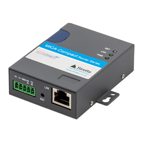
SIRETTA routeCONNECT MICA LTE Quick user guide

MICA Series
3G & 4G Industrial Router Range
Hardware Reference Manual
Rev 1.5

A member of the Olancha Group Ltd
Registered in England No. 08405712
VAT Registration No. GB163 04 0349
Siretta Ltd
Basingstoke Road
Spencers Wood
Reading
Berkshire RG7 1PW
sales
fax
email
web
+44(0)118 976 9014
+44(0)118 976 9020
www.siretta.co.uk
2
MICA Series
Hardware Reference Manual
Table of Contents
Page
Introduction 3
About Siretta 4
General Description 5
Features 6
Specications 6
MICA Series Interface 7
Ordering Information 8
Dimensions 9
MICA Series Images 10
MICA Series LED Indicators 11
Interfaces 12
LAN / WAN Port 12
SIM Socket 13
SIM Requirements 13
Antenna Connectors 14
Main Antenna Connector 15
GPS Antenna Connector 15
WiFi Antenna Connector 15
GPS 16
GPS Performance (MICA-G Variants) 16
WiFi 16
WiFi Performance (MICA-W Variants) 16
Power 17
Power Connector 17
Power Supply Requirements 18
Switching the Router ON/OFF 18
Installation 19
Considerations for Installations
Incorporating the Router
19
Power Supply Installation 20
Securing the Router 20
Safety and Product Care 21
General Precautions 21
SIM Card Precautions 21
Antenna Precautions 22
Exposure to RF Energy 22
Safety Recommendations 24
Approvals 25
Disclaimer 26
Denitions 27

A member of the Olancha Group Ltd
Registered in England No. 08405712
VAT Registration No. GB163 04 0349
Siretta Ltd
Basingstoke Road
Spencers Wood
Reading
Berkshire RG7 1PW
sales
fax
email
web
+44(0)118 976 9014
+44(0)118 976 9020
www.siretta.co.uk
3
MICA Series
Hardware Reference Manual
This document is intended to provide guidance when adding a router from the
routeCONNECT MICA Series to your system.
The MICA Series is a range of UMTS / LTE routers enabling mobile broadband and
machine to machine (M2M) industrial communication.
This document is aimed at engineers and describes the electrical characteristics,
hardware and software operation of the MICA router.
Introduction

A member of the Olancha Group Ltd
Registered in England No. 08405712
VAT Registration No. GB163 04 0349
Siretta Ltd
Basingstoke Road
Spencers Wood
Reading
Berkshire RG7 1PW
sales
fax
email
web
+44(0)118 976 9014
+44(0)118 976 9020
www.siretta.co.uk
4
MICA Series
Hardware Reference Manual
Siretta, located in Reading, United Kingdom have been manufacturing antennas,
cable assemblies and cellular modems for over 10 years. We supply our products
globally to many of the world’s leading organisations.
Whether you require an off the shelf or custom solution, Siretta has a wide portfolio of
antenna, RF cable assemblies and modems to t your application.
Our extensive knowledge and experience in the wireless market allows us to support
a wide range of customer applications, focusing on frequencies typically within the
75MHz - 5.8GHz range. These encompass the HF, VHF, ISM, GSM/GPRS/3G/4G
and GPS frequencies as well as industrial WLAN and VHF/UHF antenna/Wi-Fi
antenna solutions.
With a heavy emphasis on design, we have a team of dedicated Application
Engineers and Product Managers, backed up by Field Sales Engineers, who
specialise in wireless applications.
We have made signicant investments in R&D facilities which boast GPS hardware
development equipment and a GSM Pico Cell on site, as well as development
software and a comprehensive suite of Industrial, Scientic and Medical band, and
non ISM band frequency products. We have many technology partners enabling us to
keep at the forefront of the communications industry and offer class leading wireless
solutions.
About Siretta

A member of the Olancha Group Ltd
Registered in England No. 08405712
VAT Registration No. GB163 04 0349
Siretta Ltd
Basingstoke Road
Spencers Wood
Reading
Berkshire RG7 1PW
sales
fax
email
web
+44(0)118 976 9014
+44(0)118 976 9020
www.siretta.co.uk
5
MICA Series
Hardware Reference Manual
General Description
The Siretta MICA router series is a range of high speed industrial cellular routers in
a compact enclosure. The MICA series is offered in 3G / UMTS and 4G / LTE forms
giving reliable, secure and high speed wireless connectivity.
The MICA router series is a quality range designed for use in industrial environments
needing high performance and a robust hard enclosure as standard.
The MICA router series has been designed for remote management, telemetry,
condition monitoring, CCTV, ATMs, vending machine and other M2M applications.
The MICA router series is an ideal wireless data transfer device for high speed data
applications transferring large amounts of data.
The MICA series, using the UMTS / 3G and 4G LTE networks, gives fast transfer
speeds reaching up to 21Mbps download and up to 5.76Mbps upload for 3G and
50M upload and 100M download for 4G. The MICA router series has dual port
Ethernet capability and a single SIM as standard, with 150Mbs data rate Wi and
GPS engine as optional versions.
This makes the compact MICA router series ideal for eet tracking and device access
management. In addition, the MICA router series is available with industrial grade
VPN as an option, enabling a virtual private network service through the 3G / 4G
connection and directly access the industrial server environment.

A member of the Olancha Group Ltd
Registered in England No. 08405712
VAT Registration No. GB163 04 0349
Siretta Ltd
Basingstoke Road
Spencers Wood
Reading
Berkshire RG7 1PW
sales
fax
email
web
+44(0)118 976 9014
+44(0)118 976 9020
www.siretta.co.uk
6
MICA Series
Hardware Reference Manual
»Global 3G / UMTS bands
»European 4G / LTE bands
»High speed data via UMTS & LTE networks
»Strong resistance to electromagnetic interference
»Built-in watch dog, multi-link detection
»Compact industrial design
»Good heat and radiation endurance
»Supports DHCP server
»Supports DNS proxy and Dynamic DNS (DNSS)
»Supports timing operation
»Supports LED status indication
»Supports APN and VDPN wireless private network access
»Supports 802.11b/g/n WiFi, 150Mbps data rate
»Local and remote management
»SNMP network management, NTP support
»WAN supports PPOE, Static IP DHCP Client (with 1 x WAN and
1 x LAN option)
Features
Specications
MICA UMTS MICA LTE
3G frequency band: 850, 900, 1900, 2100MHz 850, 900, 1900, 2100MHz
4G frequency band: 800/850, 900, 1800, 1900, 2100, 2600MHz
Dimensions: 103mm x 73.5mm x 23.5mm 103mm x 73.5mm x 23.5mm
Weight: 300g 300g
Supply voltage: 7.5 - 32VDC 7.5 - 32VDC
Operating temperature range: -30 to 70°C -30 to 70°C
Antenna interface: SMA Female 2 x SMA Female
Table 1. Specications of MICA Series routers

A member of the Olancha Group Ltd
Registered in England No. 08405712
VAT Registration No. GB163 04 0349
Siretta Ltd
Basingstoke Road
Spencers Wood
Reading
Berkshire RG7 1PW
sales
fax
email
web
+44(0)118 976 9014
+44(0)118 976 9020
www.siretta.co.uk
7
MICA Series
Hardware Reference Manual
MICA Series Interface
Standard Router Features
Hardware
The MICA Series routers come with the following interfaces:
»2 x 10/100Mb Ethernet LAN
»1 x 3G SMA Female antenna interface
»2 x 4G SMA Female antenna interface
»1 x standard SIM/R-UIM interface
»1 x standard DC power interface
Optional Router Features
Optional Technologies
The MICA Series have the following optional technologies available:
»UMTS (Global 3G)
»LTE (European 4G)
Optional Interfaces
The MICA Series have the following optional interfaces available:
»1 x 10/100Mb Ethernet LAN, 1 x 10/100Mb Ethernet WAN
»1 x GPS OR WiFi SMA female antenna interface*
*WiFi and GPS are not available on a MICA simultaneously

A member of the Olancha Group Ltd
Registered in England No. 08405712
VAT Registration No. GB163 04 0349
Siretta Ltd
Basingstoke Road
Spencers Wood
Reading
Berkshire RG7 1PW
sales
fax
email
web
+44(0)118 976 9014
+44(0)118 976 9020
www.siretta.co.uk
8
MICA Series
Hardware Reference Manual
Ordering Information
Part Numbering Examples
»MICA-11-UMTS = Global UMTS Industrial Router with 1 x Ethernet LAN, 1 x Ethernet WAN and 1 x SIM
Port Interfaces
»MICA-W21-LTE = European LTE Industrial Router with 2 x Ethernet LAN and 1 x SIM Port Interfaces, with
WiFi
MICA X X X XXXX
Number of SIM Ports
1 = 1 x SIM Port
Range Identier
MICA = Industrial Router Range
Number of Ethernet Ports
1 = 1 x Ethernet LAN Port, 1 x Ethernet WAN Port
2 = 2 x Ethernet LAN Ports
Technology
UMTS = Global 3G
LTE = European 4G
Optional Antenna Interfaces*
G = GPS
W = WiFi
*WiFi and GPS are not available on a MICA simultaneously. If you do not require an
additional antenna interface, leave this blank.

A member of the Olancha Group Ltd
Registered in England No. 08405712
VAT Registration No. GB163 04 0349
Siretta Ltd
Basingstoke Road
Spencers Wood
Reading
Berkshire RG7 1PW
sales
fax
email
web
+44(0)118 976 9014
+44(0)118 976 9020
www.siretta.co.uk
9
MICA Series
Hardware Reference Manual
Dimensions
All dimensions are shown in mm.
Figure 1. MICA Series front - dimensions
Figure 2. MICA Series side - dimensions

A member of the Olancha Group Ltd
Registered in England No. 08405712
VAT Registration No. GB163 04 0349
Siretta Ltd
Basingstoke Road
Spencers Wood
Reading
Berkshire RG7 1PW
sales
fax
email
web
+44(0)118 976 9014
+44(0)118 976 9020
www.siretta.co.uk
10
MICA Series
Hardware Reference Manual
MICA Series Images
Figure 3. 3D view of the MICA Router
Figure 5. LAN, WAN/CON, Reset and Power Interfaces
Figure 4. Antenna and LED’s
Figure 6. SIM Cover

A member of the Olancha Group Ltd
Registered in England No. 08405712
VAT Registration No. GB163 04 0349
Siretta Ltd
Basingstoke Road
Spencers Wood
Reading
Berkshire RG7 1PW
sales
fax
email
web
+44(0)118 976 9014
+44(0)118 976 9020
www.siretta.co.uk
11
MICA Series
Hardware Reference Manual
The state of the MICA Router is indicated by the status LEDs as shown in table 2
below.
Silk screen Color Status Indication
NET
Green Blink Strong signal
Orange Blink Normal signal
Red Blink Weak signal
Blinking slowly (2s) Logged in to network. LED color is matched with signal
identication. (e.g. Green blink = strong online signal)
Blinking slowly (0.5s) Dialling
WLAN
Green Solid light WLAN port open but no data sending
Green Blinking quickly Data is transmitting
Green Dark WLAN port isn’t opened
LAN
Green Solid light Connection OK
Green Blinking Data sending
Green Dark LAN not connected
Table 2. Device status LED
Figure 7. MICA LED’s
MICA LED Indicators
WLAN (WiFi activity status)
WAN (Ethernet activity status)
LAN (Ethernet activity status)
NET (Network registration status)

A member of the Olancha Group Ltd
Registered in England No. 08405712
VAT Registration No. GB163 04 0349
Siretta Ltd
Basingstoke Road
Spencers Wood
Reading
Berkshire RG7 1PW
sales
fax
email
web
+44(0)118 976 9014
+44(0)118 976 9020
www.siretta.co.uk
12
MICA Series
Hardware Reference Manual
Interfaces
LAN / WAN Port
Figure 8. MICA LAN / WAN Connection
As standard, the MICA Series is supplied with 2 x 10/100Mb LAN connections.
Optionally, the MICA router can be supplied with 1 x 10/100Mb LAN and 1 x
WAN/CON connections. (Speak to your Siretta representative)
These connections can be used to connect the router directly to a computer, to
transmit wireless data or for debug testing.
LAN / Optional WAN Port
LAN Port

A member of the Olancha Group Ltd
Registered in England No. 08405712
VAT Registration No. GB163 04 0349
Siretta Ltd
Basingstoke Road
Spencers Wood
Reading
Berkshire RG7 1PW
sales
fax
email
web
+44(0)118 976 9014
+44(0)118 976 9020
www.siretta.co.uk
13
MICA Series
Hardware Reference Manual
Figure 9. SIM holder
SIM holder
SIM
Insert SIM this way
SIM Socket
Figure109. SIM card dimensions
SIM Requirements
SIM services available for the MICA series include:
»3G UMTS (850/900/1900/2100MHz)
»SMS
»4G LTE (800/850, 900, 1800, 1900, 2100, 2600MHz)
The MICA Series supports xed SIMs locked to a network and roaming SIMs which
can operate on more than one network within the home country. This allows for least
cost routing for roaming mobile data and machine to machine applications where
signal strength is variable in any given area and network selection is required.
The MICA also supports global roaming SIMs which will work with any network it can
detect, at home or abroad and can be chosen for best performance.
The MICA routers can are single SIM, supporting 1.8/3/5V with automatic SIM
detection.*
*To insert SIM card, remove blue protective shield and insert. Replace shield once SIM is inserted.

A member of the Olancha Group Ltd
Registered in England No. 08405712
VAT Registration No. GB163 04 0349
Siretta Ltd
Basingstoke Road
Spencers Wood
Reading
Berkshire RG7 1PW
sales
fax
email
web
+44(0)118 976 9014
+44(0)118 976 9020
www.siretta.co.uk
14
MICA Series
Hardware Reference Manual
Antenna Connectors
Figure 11. Antenna connectors
Main antenna connector
(3G / 4G)
WiFi / GPS antenna connector (optional on 3G series)
DIVERSITY antenna connector (standard on 4G series)
WiFi / GPS antenna connector (optional on 4G series)
Antenna Placement
When in service the antenna should be placed away from electronic devices or
other antennas. The recommended minimum distance between adjacent antennas,
operating on a similar radio band, is at least 50cm.
Antenna Connection Cable
If a cable is used to connect the antenna to the router this cable must be a high
quality low loss cable. The cable and any connectors used should have 50 ohms
impedance.
Figure 12. MICA Antennas*
*Antennas only supplied when MICA is purchased with accessories.

A member of the Olancha Group Ltd
Registered in England No. 08405712
VAT Registration No. GB163 04 0349
Siretta Ltd
Basingstoke Road
Spencers Wood
Reading
Berkshire RG7 1PW
sales
fax
email
web
+44(0)118 976 9014
+44(0)118 976 9020
www.siretta.co.uk
15
MICA Series
Hardware Reference Manual
A female SMA connector is provided to allow connection of 3G / LTE. For optimum
performance the antenna assembly connected to this router is required to have the
following characteristics:
»For 3G UMTS operation specied operation in the following bands: UMTS
850/900/1900/2100MHz
»For 4G LTE operation specied operation in the following bands: LTE 800/850,
900, 1800, 1900, 2100, 2600MHz
»The characteristic impedance on any antenna or cable assembly attached to this
router should be 50 ohms
»The antenna must be capable of handling a minimum of 2W output power
»The VSWR should be less than 3:1 to avoid damage to the router
Main Antenna
A female SMA connector is provided to allow connection of optional GPS. For opti-
mum performance the antenna assembly connected to this router is required to have
the following characteristics:
»For GPS operation specied operation in the following bands: 1575.42 MHz
»The characteristic impedance on any antenna or cable assembly attached to this
router should be 50 ohms
»The antenna must be capable of handling a minimum of 2W output power
»The VSWR should be less than 3:1 to avoid damage to the router
GPS Antenna
A female SMA connector is provided to allow connection of optional WiFi. For opti-
mum performance the antenna assembly connected to this router is required to have
the following characteristics:
»For WiFi operation specied operation in the following bands: 2.4GHz
»The characteristic impedance on any antenna or cable assembly attached to this
router should be 50 ohms
»The antenna must be capable of handling a minimum of 2W output power
»The VSWR should be less than 3:1 to avoid damage to the router
WiFi Antenna

A member of the Olancha Group Ltd
Registered in England No. 08405712
VAT Registration No. GB163 04 0349
Siretta Ltd
Basingstoke Road
Spencers Wood
Reading
Berkshire RG7 1PW
sales
fax
email
web
+44(0)118 976 9014
+44(0)118 976 9020
www.siretta.co.uk
16
MICA Series
Hardware Reference Manual
GPS
GPS Performance (MICA-G Variants)
»Advanced real time hardware correlation engine for enhanced sensitivity (better
than -165dBm for A-GPS)
»Fast Acquisition giving rapid Time-to-First-Fix (TTFF)
»Capability to monitor up to 28 channel
»Stand Alone and Assisted mode
»Integrated LNA
WiFi
WiFi Performance (MICA-W Variants)
»Standard: IEEE 802.11b/g/n
»WEP, WPA and WPA2 encryption
»Standard 150Mbps

A member of the Olancha Group Ltd
Registered in England No. 08405712
VAT Registration No. GB163 04 0349
Siretta Ltd
Basingstoke Road
Spencers Wood
Reading
Berkshire RG7 1PW
sales
fax
email
web
+44(0)118 976 9014
+44(0)118 976 9020
www.siretta.co.uk
17
MICA Series
Hardware Reference Manual
Power
Power Connector
This connector is used for supplying DC power to the router.
Figure 13. Power connector
Power connector

A member of the Olancha Group Ltd
Registered in England No. 08405712
VAT Registration No. GB163 04 0349
Siretta Ltd
Basingstoke Road
Spencers Wood
Reading
Berkshire RG7 1PW
sales
fax
email
web
+44(0)118 976 9014
+44(0)118 976 9020
www.siretta.co.uk
18
MICA Series
Hardware Reference Manual
Switching the Router ON/OFF
Power on the MICA
The MICA router is automatically powered on when powered is supplied.
Power off the MICA
The MICA router is automatically powered off when power is removed.
Restart the MICA
Press and hold reset button for at least 5 seconds.
Figure 14. Reset button
Reset button
Power Supply Requirements
A DC power supply must be connected to the power input.
Table 3. Characteristics of power input
MICA Series
Idle: 80mA @ +12VDC
Communicating: 320mA : +12VDC
Power supply: 5 - 36VDC
DC power supply polarity: Centre +ve

A member of the Olancha Group Ltd
Registered in England No. 08405712
VAT Registration No. GB163 04 0349
Siretta Ltd
Basingstoke Road
Spencers Wood
Reading
Berkshire RG7 1PW
sales
fax
email
web
+44(0)118 976 9014
+44(0)118 976 9020
www.siretta.co.uk
19
MICA Series
Hardware Reference Manual
Installation
Considerations for Installations Incorporating the MICA
There are several conditions which need to be taken into consideration when
designing your application as they might affect the router and its functionality. These
are:
Environmental conditions: The router must be installed so that the environmental
conditions stated such as temperature, humidity and vibration are satised.
Additionally, the electrical specications must not be exceeded.
Signal strength: The router/antenna has to be placed in a position that ensures
sufcient signal strength. To improve signal strength, the antenna can be moved to
a more elevated position. Signal strength usually depends on how close the router is
to the base station. You must ensure that the location at which you intend to use the
router is within the network coverage area. Degradation in signal strength can be the
result of a disturbance from another source, for example an electronic device in the
immediate vicinity.
When considering the location for the router and antenna placement, you must
consider received signal strength as well as cable length as long cable runs can
attenuate the received signal strength.
Connections of components to MICA Series routers: The system integrator is
responsible for the nal system solution. If external components are incorrectly
designed or installed it may cause radiation limits to be exceeded. For instance,
improper cable connections or incorrectly installed antennas can disturb the network
and lead to router malfunction.
Network and subscription: Before your application is used, you must ensure that
your chosen network provides the necessary telecommunication services. Contact
your service provider to obtain the necessary information.
» If you intend to use SMS in the application, ensure this is included in your
subscription.

A member of the Olancha Group Ltd
Registered in England No. 08405712
VAT Registration No. GB163 04 0349
Siretta Ltd
Basingstoke Road
Spencers Wood
Reading
Berkshire RG7 1PW
sales
fax
email
web
+44(0)118 976 9014
+44(0)118 976 9020
www.siretta.co.uk
20
MICA Series
Hardware Reference Manual
Power Supply Installations
»Use a high-quality power supply with short leads. This ensures that the voltages
at the connector pins are within the specied range, especially during the
maximum peak current of approximately 2A.
» When the router is powered from a battery or a high current supply, connect a
fast 1.25A fuse in line with the positive supply. This protects the power cabling
and router from damage.
Securing the Router
Before securing the router please take into account the amount of additional space
required for the mating connectors and cables that will be used with the router in the
application.
» Where access is restricted, it may be easier to connect all the cables to the router
prior to placing it in the application.
This manual suits for next models
2
Table of contents
Other SIRETTA Network Router manuals
SIRETTA
SIRETTA QUARTZ Series Quick user guide
SIRETTA
SIRETTA QUARTZ-GOLD Quick user guide
SIRETTA
SIRETTA QUARTZ-GOLD-W21-5G Quick user guide
SIRETTA
SIRETTA QUARTZ User manual
SIRETTA
SIRETTA QUARTZ-GOLD Series User manual
SIRETTA
SIRETTA QUARTZ-COMPACT-UMTS Quick user guide
SIRETTA
SIRETTA QUARTZ-W22-UMTS(EU) User manual
SIRETTA
SIRETTA QUARTZ-GOLD 5G NR User manual
SIRETTA
SIRETTA QUARTZ-ONYX User manual

SIRETTA
SIRETTA QUARTZ-GOLD-5G Quick user guide


