Ramblewood Green EC2-27 User manual

User Manual
EC2-27
EC2-30
EC4-60
Ramblewood Green
WWW.RAMBLEWOODGREEN.COM

GENERAL INFORMATION
This appliance is designed for domestic household use. The User Manual contains
important product safety & installation information.
Your safety is of the utmost importance. Please ensure you read this booklet before
attempting to install or use the appliance, and contact RambleWood Green if you
have any question.
Safety Information
The appliance should only be installed & serviced by a qualified technician.
The adjacent furniture and all materials used in installation must be able to
withstand a minimum of 85°C above the ambient temperature of the room.
Certain types of vinyl or laminate kitchen furniture are particularly prone to heat
damage or discoloration at temperatures below the 85°C.
Damage caused by the appliance being installed in contravention of this
temperature limit will be the liability of the user.
You should not store or place flammable or highly flammable liquids/materials on
top of or near this product. Items made from aluminum, plastic or plastic film
should also be kept away from the appliance, as they may fuse to the surface.
Infant should be kept away from this appliance. If children are allowed in kitchen,
please keep them under close supervision at all times. Older children should only
be allowed to use the product under adult supervision.
The power cables should not be in close contact with the hot glass surface or
cookware.
Fat and oil can be ignited extremely quickly when overheated. When cooking with
fat and oil the appliance should not be left unattended.
Under any circumstance the cookware should not be empty when the power is on.
Insure all cooking zones are switched off after use.
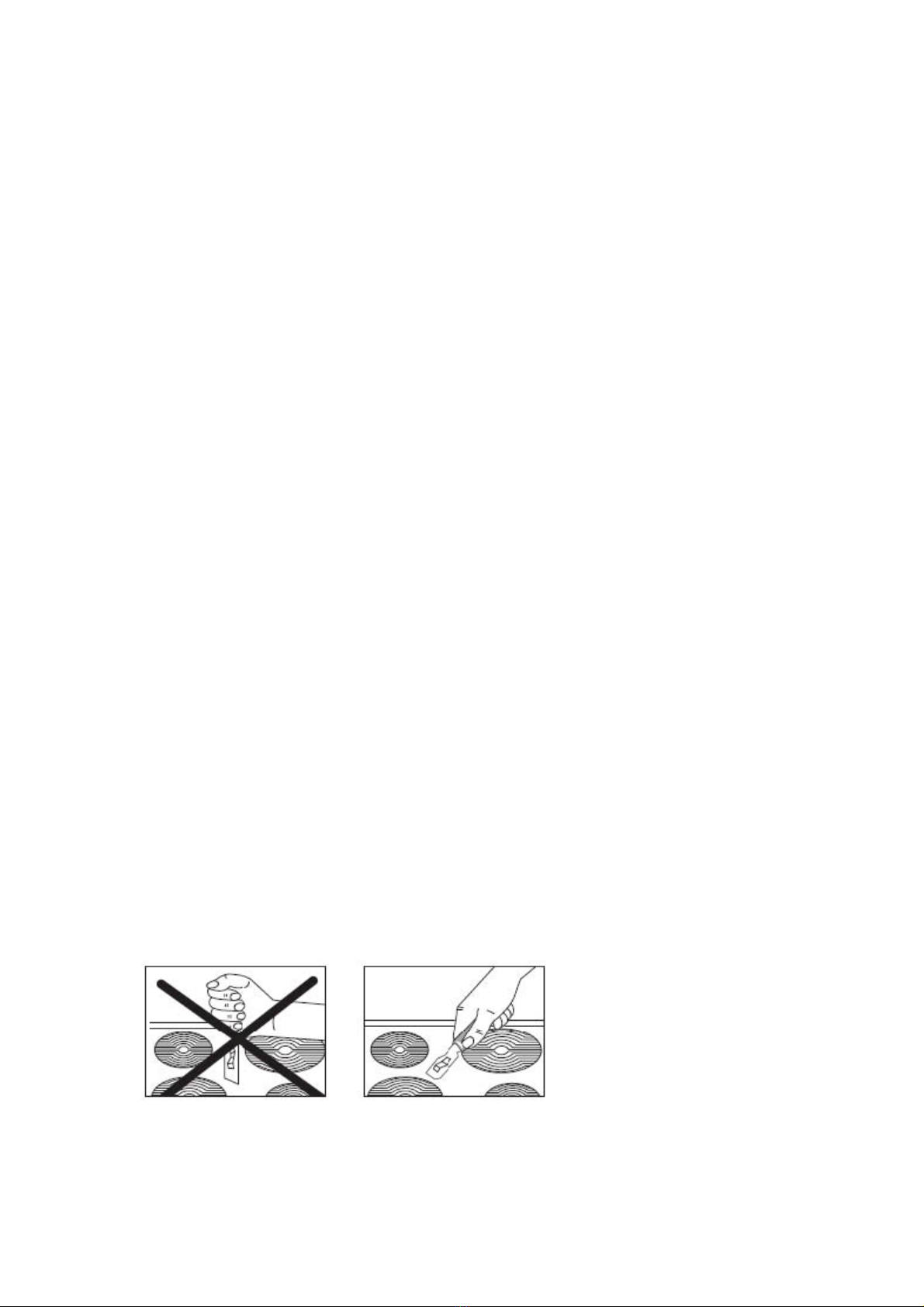
The ceramic glass can be damaged /cracked by external shock & vibration. Cast
iron and aluminum cookware with sharp edge may scratch the ceramic surface if
they are dragged across it.

IMPORTANT: The ceramic glass is tough; however it is not unbreakable and
can be damaged if heavy or sharp objects are placed on top. DO NOT USE THE
UNIT IF ITS SURFACE IS BROKEN OR CRACKED. YOU SHOULD
CONTACT RAMBLEWOOD GREEN IMMEDIATELY.
Specifications
Product specifications and Electrical details:
MODELS
EC2
-
27
EC2-30 EC4-60
Voltage 110-120V, 60Hz 220-240V, 60Hz 220-240V, 60Hz
Current 19.8A-21.7A 13A 28A
Burner Power 1400W+1200W 1800W/1200W
1800Wx2;
1200Wx2
Max power kW 2180-2600W 3000 W 6000 W
Front Side control operation YES YES YES
Electrical cable type 3 core x 3.31mm² 3 core x 1.5 mm² 3 core x 2.5 mm²
Control panel layout and Cooking zone indicators
EC2-27, EC2-30
EC4-60

OPERATION GUIDELINE
First Time Use
Any film or stickers on the glass surface should be removed before use.
You should switch on one cooking zone at a time, for 5 minutes at maximum level.
This will help to remove any odor that exists and evaporate any humidity formed after
exit factory.
Operation Guideline
All operations are performed by means of the 2 or 4 control knobs.
Control knob can be turned clockwise to select heating/power level. Numbers on
the dial indicate the power level from 1 to 9, with 9 is the maximum.
Marking below each knob indicates the zone it controls.
The areas where the heat radiates are marked by 2 or 4 circles on ceramic glass
surface. Saucepans must be positioned exactly on top of these zones for efficient
heating.
Cleaning and maintenance
Glass surface should be cleaned regularly.
IMPORTANT: Clean the unit when power is off & the glass surface is cool.
Using the Scraper
The scraper should be placed against glass surface at an angle. Residues can
be removed by sliding the blade gently.

INSTALLATION
The installation and service must be conducted by a qualified technician, in accordance
with national & local regulation.
Product dimensions and Aperture dimensions:
Unpacking the appliance
When unpacking the appliance please check the following items are contained within the
box:
1 hob
1 Ceramic hob scraper
1 Installation and instruction manual
4 Fixing brackets
4 Fixing screws
4 Spring clips
1 Sealing strip
Positioning
The adjacent furniture must be able to withstand a minimum temperature rise of 85°C
above the ambient temperature.
MODEL
A
B
C
D
E
EC2
-
27
290mm
510mm
270mm
490mm
57
mm
EC2
-
30
290mm
510mm
270mm
490mm
53mm
EC4
-
60
770mm
51
0mm
750mm
490mm
53mm

o Cut a hole in countertop per drawings shown above.
o IMPORTANT: You must leave clearance of at least 25 mm between the
underneath of the unit and any surface below it.
Carefully turn the hob upside down and place it on a cushioned mat.
Apply the sealing strip provided around the edge of the appliance.
Do not leave a gap in the sealing agent or overlap the thickness.
IMPORTANT: Do not use a silicon sealant to seal the appliance against the
aperture. This will make it difficult to remove the hob from aperture in future for
service.

(A) Clip
(B) Fixing bracket
(C) Screw
You should insert a clip (A) into the holes which are located in each corner of the hob.
Place the fixing brackets (B) over each hole and clip, and then place a screw (C)
through the hole and fixing bracket (B). Tighten the screws slowly. IMPORTANT: Do
not tighten the screws fully.
Carefully turn the hob back over and then gently lower it into the aperture hole that
you have cut out.
On the underneath of the hob, locate the fixing brackets (B) and turn them so that they
locate on the underneath of the worktop and the hob.
Fully tighten the screws (C) to secure the hob into position.
WARNING: THIS APPLIANCE MUST BE EARTHED.
This appliance must be wired into a 30 A fused spur outlet, having 3 mm contact
separation and placed in an easily accessible position adjacent to the unit.
Cable type: EC2-27, SJT 3 core x 3.31 mm²
Cable type: EC2-30, H05 RR-F 3 core x 1.5 mm²
Cable type: EC4-60, H05 RR-F 3 core x 2.5 mm²

Replacing the mains supply cable
If the power supply cord is damaged, it must be replaced by manufacturer or qualified
technician, per national & local safety regulation/guideline.
The main terminal block is located on the underside of the hob and terminals are
accessible by removing the terminal block cover screw.
EC2-27
EC2-30
EC4-60
The cable connections must be in accordance with the diagram located on the bottom
of the hob.

EC2-27
EC2-30
EC4-60
The “Green / yellow” earth wire must be connected to the Earth marked. It must be
about 10 mm longer than the live and neutral wires.
The “White / Blue” neutral wire must be connected to the terminal marked with letter
(N)
The “Black” live wire must be connected to the terminal marked with letter (L).
Please insure cable is not kinked or trapped when the hob is in position.

220V AC Model Wiring Instructions
by Ramblewood Green
Some of the customers who purchased 220V AC induction/electric cooktop
(EC2-30, EC4-60 & ICQ2-31C1...etc.) have asked about the electrical connection.
The following are a set of instructions that customers have found useful. Please
first note that our unit uses the standard US color code convention - Black (hot),
White (neutral) and Green (ground), but that some of the units might use the British
convention - Brown (hot), Blue (neutral) and Yellow/Green (ground). In either case,
you will need to do the following:
For connection to a junction box without the use of a 220V plug:
Connect the hot wire from the unit to the black wire in the circuit box (in
junction box) and the neutral wire from the unit to the red wire from the circuit
box (in junction box).
Connect the ground wire from the unit to the white wire from the circuit box
(in junction box).
Fasten the ground wire coming in from the circuit box (in junction box) to the
ground lead on the junction box.
The hot and neutral wires from the induction unit are used as both hot lines
and must be connected with the two hot lines from the circuit box - the black
and the red lines.

For connection using a 220V plug:
Connect the hot and neutral wires from the unit to the hot leads/prong on the
220V plug and the ground wire to the neutral lead/prong with the green
paint.
Connect the black and red wires from the junction box to the hot leads on the
220V faceplate, and the white wire to the neutral lead with green paint.
Fasten the ground wire coming in from the circuit box (in junction box) to the
ground lead on the junction box.
Again, note that the hot and neutral wires from the induction unit are used as
both hot lines and must be connected with the two hot leads/prong on the
220V plug.
We have attached sample pictures of 220V plug and face-plate at the end of the
manual posted in;
http://ramblewoodgreen.com/upload/220%20V_wiring-28-7-15_less-photo.pdf
or
http://ramblewoodgreen.com/upload/220%20V_wiring-28-7-15_less-photo_copy1.
pdf
Thank you and please contact us if you have any questions.
DO NOT ATTEMPT TO REPAIR THE APPLIANCE YOURSELF.
This manual suits for next models
2
Table of contents
Other Ramblewood Green Cooktop manuals

Ramblewood Green
Ramblewood Green GC2-43N User manual

Ramblewood Green
Ramblewood Green GC4-50N User manual

Ramblewood Green
Ramblewood Green EC2-30 User manual

Ramblewood Green
Ramblewood Green EC2-30 User manual

Ramblewood Green
Ramblewood Green GC2-37P User manual

Ramblewood Green
Ramblewood Green EC4-70 User manual

Ramblewood Green
Ramblewood Green GC2-48N User manual

Ramblewood Green
Ramblewood Green EC2-18 User manual