• Periodically check and tighten all fasteners.
• Stripped, fractured, or bent bolts or nuts need to be
replaced.
• After washing of the vehicle make sure to fully dry all
surfaces
PLEASE NOTE PARKING SENSORS ARE EXTREMELY
DELICATE AND MUST BE HANDLED WITH CARE!
Do NOT touch or shift the clear rubber grommet that
surrounds the sensor face. DO NOT glue housing into place
until orientation and functionality is determined.
Troubleshooting Vehicle Sensors
• Start with a general inspection of the sensor tment.
Check that both the sensors and the sensor clips are fully
secure and the sensors are properly centered in the
housing.
• Conrm plastic housing is in the correct mounting holes.
Misplaced sensor housings could compress sensor and
give false readings or faults.
• Use a clean microber to wipe the front face of the
sensor.
• Inspect connection. Be sure that the sensor is rmly seat-
ed into the harness.
• Run through several start cycles (i.e. fully turn the vehicle
on and o).
• Finally, disconnect the battery to reset the sensors.
If your vehicle has adaptive cruise, please ensure that your adaptive
cruise is working correctly once the Ranch Hand bumper is installed.
Adaptive cruise may need to be cleaned or adjusted to ensure it func-
tions properly. See your owner’s manual for care of the adaptive cruise.
Special care should be exercised in the handling, storage and
installation of Kaspar Ranch Hand equipment. The actual weight
of each piece of equipment will vary depending on style and
model. The weight of the equipment is sucient in volume to
warrant special care, assistance and in some instances, the use
of mechanical equipment during the transfer and installation
of the equipment. Do not assume a position directly under the
equipment during installation. Be sure the equipment has been
connected and stabilized during installation to prevent falling
or shifting of positions. Periodically check tightness of bolts to
make sure they are tight, and unlikely to fail.
• In order to help you make informed decisions about safe-
ty, we have provided installation instructions and other
information.
• These instructions alert you to potential injury hazards
• Please do a job safety analysis before each task to identi-
fy potential hazards for your situation and remove/pro-
tect against them.
• You must use your own good judgment.
• Read and understand all safety precautions and instruc-
tions before installing this product
FAILURE TO OBSERVE THESE INSTRUCTIONS COULD LEAD TO
SEVERE INJURY OR DEATH.
• Always remove jewelry and wear eye protection.
• Always use extreme caution when jacking up a vehicle for
work. Set emergency brake and use tire blocks. Locate and
use the vehicle manufacturers designated lifting points. Use
jack stands.
• Always use appropriate and adequate care in lifting compo-
nents into place.
• Always insure components will remain secure during installa-
tion and operation.
• Always wear safety glasses when installing this kit. A drilling
operation will cause ying metal chips. Flying chips can cause
serious eye injury.
• Always use extreme caution when drilling on a vehicle. Thor-
oughly inspect the area to be drilled (on both sides of ma-
terial) prior to drilling, and relocate any objects that may be
damaged.
• Always use extreme caution when cutting and trimming during
tting.
• Always tighten all nuts and bolts securely per installation
instructions.
• Always route electrical cables carefully. Avoid moving parts,
components that become hot and rough or sharp edges.
• Always insulate and protect all exposed wiring and electrical
terminals.
• Always perform regular inspections and maintenance on
mounts and related hardware.
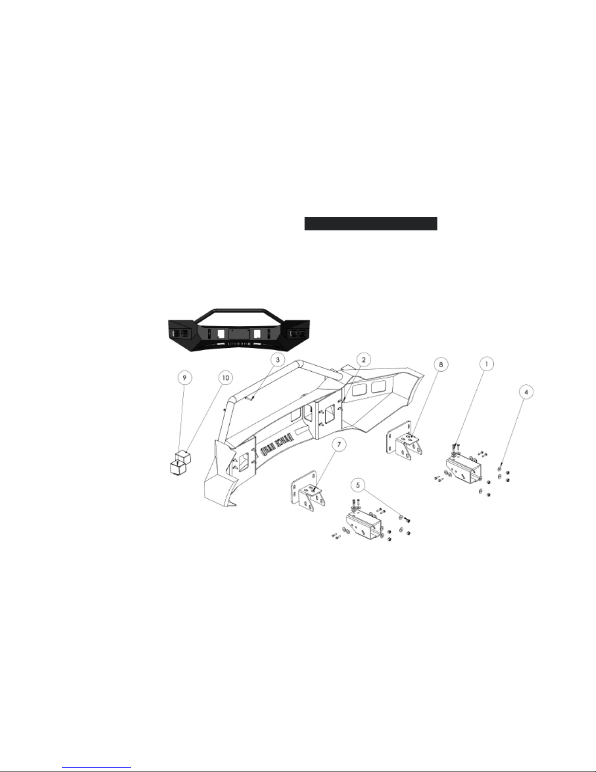
DESCRIPTION
PART #:
2011-16 Ford Super Duty
Horizon Front Bumper
HFF111BMT
INSTALLATION
INSTRUCTIONS
HAZARD
SAFETY
WARNINGMAINTENANCE/CARE
SENSOR DISCLAIMER
APPENDIX