Ranger 3DP4100 User manual

OPERATION MANUAL
RECEIVING
The shipment should be thoroughly inspected as soon as it
is received. The signed Bill of Lading is acknowledgement
by the shipping carrier as receipt of this product as listed
in your invoice as being in a good condition of shipment. If
any of these goods listed on this Bill of Lading are missing
or damaged, do not accept merchandise until the shipping
carrier makes a notation on the freight bill of the missing or
damaged goods. Do this for your own protection.
BE SAFE
Your new alignment system was designed and built with
safety in mind. However, your overall safety can be
increased with proper training and thoughtful operation
on the part of the operator. DO NOT operate or repair this
equipment without reading this manual and the important
safety instructions shown inside. Keep this operation man-
ual near the alignment system at all times. Make sure that
ALL USERS read and understand this manual.
1645 Lemonwood Dr.
Santa Paula, CA. 93060, USA
Toll Free 1-800-253-2363
Tel: 1-805-933-9970
Fax: 1-805-933-9160
www.bendpak.com
IMPORTANT SAFETY INSTRUCTIONS
SAVE THESE INSTRUCTIONS
PLEASEREADTHEENTIRECONTENTSOFTHISMANUALPRIORTOINSTALLATIONAND
OPERATION.BY PROCEEDING WITH THIS 3-D ALIGNER INSTALLATION AND OPERATION
YOU AGREE THAT YOU FULLY UNDERSTAND AND COMPREHEND THE FULL CONTENTS
OF THIS DOCUMENT. FORWARD THIS IMPORTANT MANUAL TO ALL OPERATORS.
Revision A 02/23/16
P/N 5900963
MODEL: 3DP4100
TARGET 3D PRO
WHEEL ALIGNMENT SYSTEM

2
Product Warranty . . . . . . . . . . . . . . . . . . . . . . . . . . . . . . . . . .. . .. . . . . . . . . . . . . . . . . . . . . . . . . . . . . . . . . . . . . . . . . . . . . . . 3
Definitions of Hazard Levels . . . . . . . . . . . . . . . . . . . . . . . . . . . . . . . . . . . . . . . . . . . . . . . . . . . . . . . . . . . . . . . . . . . . . . . . . 4
Important Safety Instructions . . . . . . . . . . . . . . . . . . . . . . . . . . . . . . . . . . . . . . . . . . . . . . . . . . . . . . . . . . . . . . . . . . . . . . . . . . . 5 - 7
Owner’s Responsibility. . . . . . . . . . . . . . . . . . . . . . . . . . . . . . . . . . . . . . . . . . . . . . . . . . . . . . . . . . . .. . . . . . . . . . . . . . . . . . . . 7
Installation Location . . . . . . . . . . . . . . . . . . . . . . . . . . . . . . . . . . . . . . . . . . . . .. . . . . . . . . . . . . . . . . . . . . . . . . . . . . . . . . .. . . .8
System Requirements . . . . . . . . . . . . . . . . . . . . . . . . . . . . . . . . . . . . . . . . . . . . . . . . . . . . . . . . . . . . . . . . . . . . . . . . . . . . . . . 9
Alignment Angles . . . . . . . . . . . . . . . . . . . . . . . . . . . . . . . . . . . . . . . . . . . . . . . . . . . . . . . . . . . . . . . . . . . . . . . . . . . .. . . .10 - 12
Preparation Before Alignment . . . . . . . . . . . . . . . . . . . . . . . . . . . . . . . . . . . . . . . . . . . . . . . . . . . . . .. . . . . . . . . . . . . .. . . . . . . 13 - 14
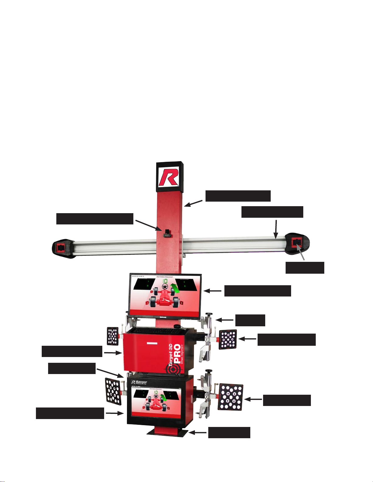
Cameras and Target Position . . . . . . . . . . . . . . . . . . . . . . . .. . .. . . . . . . . . . . . . . . . . . . . . . . . . . . . . . . . . . . . . . . . . . . . . . . 15
Adjusting Camera Beam . . . . . . . . . . . . . . . . . . . . . . . . . . . . . . . . . . . . . . . . . . . . . . . . . . . . . . . . . . . . . . . . . . . . . . . . . . . 15
Camera LED Indicators . . . . . . . . . . . . . . . . . . . . . . . . . . . . . . . . . . . . . . . . . . . . . . . . . . . . . . . . . . . . . . . . . . . . . . . . . . . . .15 - 16
Installing Clamps . . . . . . . . . . . . . . . . . . . . . . . . . . . . . . . . . . . . . . . . . . . . . . . . . . . . . . . . . . .. . . . . . . . . . . . . . . . . . . . 17
Before Measurement . . . . . . . . . . . . . . . . . . . . . . . . . . . . . . . . . . . . . . . . . .. . . . . . . . . . . . . . . . . . . . . . . . . . . . . . . . . .. . . . 18
Measurement Results . . . . . . . . . . . . . . . . . . . . . . . . . . . . . . . . . . . . . . . . . . . . . . . . . . . . . . . . . . . . . . . . . . . . . . . . . . . . . . 19
Adjusting Screen Buttons . . . . . . . . . . . . . . . . . . . . . . . . . . . . . . . . . . . . . . . . . . . . . . . . . . . . . . . . . . . . . . . . . . . . . .. . . . . . . 20
Search Targets . . . . . . . . . . . . . . . . . . . . . . . . . . . . . . . . . . . . . . . . . . . . . . . . . . . . . . . . . . . . .. . . . . . . . . . . . . .. . . . . . . . . 21
Lifting Instructions . . . . . . . . . . . . . . . . . . . . . . . . . . . . . . . . . .. . .. . . . . . . . . . . . . . . . . . . . . . . . . . . . . . . . . . . . . . . . . . . . .22
Target Blocked Insdicators. . . . . . . . . . . . . . . . . . . . . . . . . . . . . . . . . . . . . . . . . . . . . . . . . . . . . . . . . . . . . . . . . . . . . . . . . . . 23
Software Program Navigation . . . . . . . . . . . . . . . . . . . . . . . . . . . . . . . . . . . . . . . . . . . . . . . . . . . . . . . . . . . . . . . . . . . . . . . . . . . 24
Keyboard Navigation . . . . . . . . . . . . . . . . . . . . . . . . . . . . . . . . . . . . . . . . . . . . . . . . . . . . . . . . . .. . . . . . . . . . . . . . . . . . . .24
Search Targets Screen of Fixed Version 3D alignment . . . . . . . . . . . . . . . . . . . . . . .. . . . . . . . . . . . . . . . . . . . . . . . . . . . . . . . . .. . .25
Target Gray Values Adjustment. . . . . . . . . . . . . . . . . . . . . . . . . . . . . . . . . . . . . . . . . . . . . . . . . . . . . . . . . . . . . . . . . . . . . . . . .26
Gray Values Front & Rear Targets . . . . . . . . . . . . . . . . . . . . . . . . . . . . . . . . . . . . . . . . . . . . . . . . . . . . . . . . . . . . . . . .. . . . . 27
Measurement Procedures . . . . . . . . . . . . . . . . . . . . . . . . . . . . . . . . . . . . . . . . . . . . . . . . . . . . . .. . . . . . . . . . . . . .. . . . . . . 28 - 33
Measurement Ways. . . . . . . . . . . . . . . . . . . . . . . . . . . .. .. . . . . . . . . . . . . . . . . . . . . . . . . . . . . . . . . . . . . . . . . . . . . . . . 33 - 34
Targets Exposure Values Adjustment . . . . . . . . . . . . . . . . . . . . . . . . . . . . . . . . . . . . . . . . . . . . . . . . . . . . . . . . . . . . . . . .34 - 35
Super Measurement . . . . . . . . . . . . . . . . . . . . . . . . . . . . . . . . . . . . . . . . . . . . . . . . . . . . . . . . . . . . . . . . . . . . . . . . . . .. . . . 36 - 37
Conventional Measurement . . . . . . . . . . . . . . . . . . . . . . . . . . . . . . . . . . . . . . . . . . . . . . . . . . . . . . . . . . .. . . . . . . . . . . . . . 38 - 41
Single Direction Measurement . . . . . . . . . . . . . . . . . . . . . . . . . . . . . . . . . . . .. . . . . . . . . . . . . . . . . . . . . . . . . . . . . . . . . .. . 41 - 43
Short Distance Measurement . . . . . . . . . . . . . . . . . . . . . . . . . . . . . . . . . . . . . . . . . . . . . . . . . . . . . . . . . . . . . . . . . . . . . . . .43 - 47
Lift Measurement . . . . . . . . . . . . . . . . . . . . . . . . . . . . . . . . . . . . . . . . . . . . . . . . . . . . . . . . . . . . . . . . . . . . . . . . . . . . . . . .47 - 53
Caster Measurement . . . . . . . . . . . . . . . . . . . . . . . . . . . . . . . . . . . . . . . . . . . . . . . . . . . . . .. . . . . . . . . . . . . .. . . . . 53 - 61
Straighten the Steering Wheel by Eye. . . . . . . . . . . . . . . . . . . . . . . . . . . . .. . .. . . . . . . . . . . . . . . . . . . . . . . . . . . . . . . . . . . . . . . . . . .61 - 63
Report Before Adjustment . . . . . . . . . . . . . . . . . . . . . . . . . . . . . . . . . . . . . . . . . . . . . . . . . . . . . . . . . . . . . . . . . . . . . . . . . . 63
Adjustment and Widgets . . . . . . . . . . . . . . . . . . . . . . . . . . . . . . . . . . . . . . . . . . . . . . . . . . . . . . . . . . . . . . . . . . . . . . . . . . 64 - 65
Oil Gauge Status . . . . . . . . . . . . . . . . . . . . . . . . . . . . . . . . . . . . . . . . . . . . . . . . . . . . . . . . . .. . . . . . . . . . . . . . . . . . .66
Digital Type Status Explanation . . . . . . . . . . . . . . . . . . . . . . . . . . . . . . . . . . . . . . .. . . . . . . . . . . . . . . . . . . . . . . . . . . . . . . . . .. . .67
Enlarge Adjustment Values . . . . . . . . . . . . . . . . . . . . . . . . . . . . . . . . . . . . . . . . . . . . . . . . . . . . . . . . . . . . . . . . . . . . . . . . . . . . . 68
Unit Convert . . . . . . . . . . . . . . . . . . . . . . . . . . . . . . . . . . . . . . . . . . . . . . . . . . . . . . . . . . . . . . . . . . . . . . . . . . . . . . . . . .. . . .68
Degree and Minute Unit Convert . . . . . . . . . . . . . . . . . . . . . . . . . . . . . . . . . . . . . . . . . . . . . . . . . . . . . .. . . . . . . . . . . . . .. . . . . . . . .69
Toe Unit Convert . . . . . . . . . . . . . . . . . . . . . . . . . . . . . . .. . .. . . . . . . . . . . . . . . . . . . . . . . . . . . . . . . . . . . . . . . . . . . . 69 - 70
Summary Measurement Values . . . . . . . . . . . . . . . . . . . . . . . . . . . . . . . . . . . . . . . . . . . . . . . . . . . . . . . . . . . . . . . . . . . . . . . . . 71
Caster Adjustment . . . . . . . . . . . . . . . . . . . . . . . . . . . . . . . . . . . . . . . . . . . . . . . . . . . . . . . . . . . . . . . . . . . . . . . . . . . . . . . . .72
Rear Wheels Adjustment . . . . . . . . . . . . . . . . . . . . . . . . . . . . . . . . . . . . . . . . . . . . . . . . . . . . . . . . .. . . . . . . . . . . . . . . . . . 72 - 75
Lift Adjustment . . . . . . . . . . . . . . . . . . . . . . . . . . . . . . . . . . . . . . . . . . . . . . .. . . . . . . . . . . . . . . . . . . . . . . . . . . . . . . . . .. . 75 - 76
Single Wheel Measurement . . . . . . . . . . . . . . . . . . . . . . . . . . . . . . . . . . . . . . . . . . . . . . . . . . . . . . . . . . . . . . . . . . . . . . . . .77 - 79
Front Wheels Adjustment . . . . . . . . . . . . . . . . . . . . . . . . . . . . . . . . . . . . . . . . . . . . . . . . . . . . . . . . . . . . . . . . . . . . . . . . . .. . . .80 - 81
Front Wheels Adjustment - Steering Wheel Adjustment . . . . . . . . . . . . . . . . . . . . . . . . . . . . . . .. . . . . . . . . . . . . .. . . . . . . 82 - 85
Front Wheels Adjustment - Camber at Zero Toe . . . . . . . . . . . . . . . . . . . . . . . . . . . . . . . . . . . . . . . . . . . . . . . . . . . . . .86 - 89
Report After Adjustment . . . . . . . . . . . . . . . . . . . . . . . . . . . . . . . . . . . . . . . . . . . . . . . . . . . . . .. . . . . . . . . . . . . .. . . . . . . . . 89
System Maintenance . . . . . . . . . . . . . . . . . . . . . . . . . . . . . . . . .. . .. . . . . . . . . . . . . . . . . . . . . . . . . . . . . . . . . . . . . . . . . . . . 90 - 97
Camera Calibration . . . . . . . . . . . . . . . . . . . . . . . . . . . . . . . . . . . . . . . . . . . . . . . . . . . . . . . . . . . . . . . . . . . . . . . . .. . . . . . . 97
Camera Test . . . . . . . . . . . . . . . . . . . . . . . . . . . . . . . . . . . . . . . . . . . . . . . . . . . . . . . . . . . . . . . . . . . . . . . . .. . . . . . . . . . . 116
Add Vehicle Specification . . . . . . . . . . . . . . . . . . . . . . . . . . . . . . . . . . . . . . . . . . . . . . . . . . . . . . . . . . . . . . . . . . . . . .. . . . . . . . . . .117 - 125
Troubleshooting. . . . . . . . . . . . . . . . . . . . . . . . . . . . . . . . . . . . . . . . . . . . . . . . . . . . . . . . . . . . . . . . . . . . . . .. . . . . . . . . . 126 - 128
TABLE OF CONTENTS

READ THIS ENTIRE MANUAL
BEFORE OPERATION BEGINS
RECORD HERE THE FOLLOWING INFORMATION
WHICH IS LOCATED ON THE SERIAL NUMBER DATA TAG
PRODUCT WARRANTY
Your new alignment system is warranted for one year on equipment structure; one year on all operating components and
tooling/accessories, to the original purchaser, to be free of defects in material and workmanship. The manufacturer shall
repair or replace at their option for this period those parts returned to the factory freight prepaid which prove upon inspection
to be defective. The manufacturer will pay labor costs for the first 12 months only on parts returned as previously described.
The warranty does not extend to:
1. Defects caused by ordinary wear, abuse, misuse, shipping damage, improper installation, voltage or lack of required
maintenance.
2. Damages resulting from purchaser’s neglect or failure to operate products in accordance with instructions provided in
the owner’s manual(s) and/or other accompanying instructions supplied.
3. Normal wear items or service normally required to maintain the product in a safe operating
condition.
4. Any component damaged in shipment.
5. Other items not listed but may be considered general wear parts.
6. Damage caused by rain, excessive humidity, corrosive environments or other contaminant’s.
THESE WARRANTIES DO NOT EXTEND TO ANY COSMETIC DEFECT NOT INTERFERING WITH
EQUIPMENT FUNCTIONALITY OR ANY INCIDENTAL, INDIRECT, OR CONSEQUENTIAL LOSS,
DAMAGE, OR EXPENSE THAT MAY RESULT FROM ANY DEFECT, FAILURE, OR
MALFUNCTION OF A BENDPAK INC./ RANGER PRODUCT OR THE BREACH OR DELAY IN
PERFORMANCE OF THE WARRANTY.
WARRANTY IS NOT VALID UNLESS
WARRANTY CARD IS RETURNED
No part of this publication maybe translated, stored in an electronic retrieval system, reproduced, or partially or totally
adapted by any means (including microfilm and Photostats) without prior permission. Copyright © 2011 RANGER All rights
reserved. Dell, Canon, Microsoft, Windows 7, MS and MS-DOS are registered trademarks. Windows and the Windows logo
are trademarks of Microsoft Corporation. IBM is a registered trademark of IBM Corporation.
3

4
BEFORE YOU BEGIN
NOTIFY THE CARRIER AT ONCE if any hidden loss or
damage is discovered after receipt and request the carrier
to make an inspection. If the carrier will not do so, prepare
a signed statement to the effect that you have notified the
carrier (on a specific date) and that the carrier has failed to
comply with your request.
IT IS DIFFICULT TO COLLECT FOR LOSS OR DAMAGE
AFTERYOUHAVEGIVENCARRIERACLEARRECEIPT.
Support claim with copies of the bill of lading, freight bill,
invoice, and photographs, if available. BendPak’s
willingness to assist in helping you process your claim does
not make BendPak responsible for collection of claims or
replacement of lost or damaged materials.
IMPORTANT NOTICE
Do not attempt to install this machine if you have never
been trained on basic automotive service equipment
installation procedures. Never attempt to lift components
without proper lifting tools such as a forklift or cranes. Stay
clear of any moving parts that can fall and cause injury.
These instructions must be followed to ensure proper
installation and operation of your 3D Pro wheel aligner.
Failure to comply with these instructions can result in
serious bodily harm and void product warranty.
Manufacturer will assume no liability for loss or damage
of any kind, expressed or implied resulting from improper
installation or use of this product.
PLEASE READ ENTIRE MANUAL
PRIOR TO INSTALLATION
OWNER’S RESPONSIBILITY
To maintain equipment and user safety, the responsibility
of the owner is to read and follow these instructions:
t Follow all installation and operation instructions.
t Make sure installation conforms to all applicable Local,
State, and Federal Codes, Rules, and Regulations;
such as State and Federal OSHA Regulations and
Electrical Codes.
t Carefully check the equipment for correct initial function.
t Read and follow the safety instructions. Keep them
readily available for machine operators.
tMake certain all operators are properly trained, know
how to safely and correctly operate the unit, and are
properly supervised.
t Allow unit operation only with all parts in place and
operating safely.
t Carefully inspect the unit on a regular basis and
perform all maintenance as required.
t Service and maintain the unit only with authorized or
approved replacement parts.
t Keep all instructions permanently with the unit and
all decals on the unit clean and visible.
DEFINITIONS OF
HAZARD LEVELS
Identify the hazard levels used in this manual with the
following definitions and signal words:
Watch for this symbol as it means: Immediate hazards
which will result in severe personal injury or death.
Watch for this symbol as it means: Hazards or unsafe
practices which could result in severe personal injury or
death.
Watch for this symbol as it means: Hazards or unsafe
practices which may result in minor personal injury,
product or property damage.
INSTALLER / OPERATOR
PROTECTIVE EQUIPMENT
Personal protective equipment helps makes installation
and operation safer, however, it does not take the place
of safe operating practices. Always wear durable work
clothing during any installation and/or service activity.
Shop aprons or shop coats may also be worn, however
loose-fitting clothing should be avoided.
Tight-fitting leather gloves are recommended to protect
the technician’s hands when handling parts. Sturdy
leather steel-toe work shoes and oil resistant soles should
be used by all service personnel to help prevent injury
during typical installation and operation activities.
Eye protection is essential during
installation and operation
activities. Safety glasses with
side shields, goggles, or face
shields are acceptable. Back
belts provide support during
lifting activities and are also helpful in providing worker
protection. Consideration should also be given to the use
of hearing protection if service activity is performed in an
enclosed area, or if noise levels are high.

5
Do not attempt to operate this equipment if you have never been trained on basic alignment procedures / automotive lift
operation.
IMPORTANT SAFETY INFORMATION
For your safety, read this manual thoroughly before operating the equipment. The Alignment System is intended for use
by properly trained skilled automotive technicians. The safety messages presented in this section and throughout the
manual are reminders to the operator to exercise extreme care when performing wheel alignments with this product.
It is assumed that, prior to using the Alignment System, the operator has a thorough understanding of the vehicle
systems being serviced. In addition, it is assumed he has a thorough knowledge of the operation and safety features of
the alignment rack or lift, and has the proper hand and power tools necessary to perform wheel alignments.
When using your garage equipment, basic safety precautions should always be followed, including:
1. Read all instructions and warning labels.
2. Care must be taken as burns can occur from touching hot parts.
3. Do not operate equipment with a damaged power cord or if the equipment has been dropped or damaged until it has
been examined by a qualified serviceman.
4. Do not let cord hang over edge of table, bench or counter or come in contact with hot manifolds or moving fan
blades.
5. If an extension cord is necessary, a cord with a current rating equal to or more than that of the equipment should be
used. Cords rated for less than the equipment may overheat. Care should be taken to arrange the cord so that it will
not be tripped over or pulled.
6. Always unplug equipment from electrical outlet when not in use. Never use the cord to pull the plug from the outlet.
Grasp plug and pull to disconnect.
7. DO NOT TURN POWER OFF when the computer is running, this can destroy the software.
8. Let equipment cool completely before putting away. Loop cord loosely around equipment when storing.
9. To reduce the risk of fire, do not operate equipment in the vicinity of open containers of flammable liquids, such as
gasoline.
10. Adequate ventilation should be provided when working on operating internal combustion engines.
11. Keep hair, loose clothing, fingers, and all parts of body away from moving parts.
12. To reduce the risk of electrical shock, do not use on wet surfaces or expose to rain.
13. Use only as described in this manual. Use only manufacturer’s recommended attachments.
14. ALWAYS WEAR SAFETY GLASSES. Everyday eyeglasses only have impact resistant lenses, they are NOT safety
glasses.
IMPORTANT
SAVE THESE INSTRUCTIONS
DO NOT DISCARD

6
Risk of electrical shock
t Do not operate equipment with a damaged power cord or if the equipment has been dropped or
damaged, until it has been examined by a qualified service person.
t If an extension cord is necessary, a cord with a current rating equal to or greater than that of the
equipment should be used. Cords rated for less current than the equipment can overheat.
t Unplug equipment from electrical outlet when not in use. Never use the cord to pull the plug from
the outlet. Grasp plug and pull to disconnect.
t Do not expose the equipment to rain. Do not use on wet surfaces.
t Plug unit into correct power supply.
t Do not remove or bypass grounding pin.
t Contact with high voltages can cause death or serious injury.
Risk of electrical shock. High voltages are present within the console unit
t There are no user serviceable items within the console other than the keyboard and printer.
t Service on the unit must be performed by qualified personnel.
t Do not open any part of the console other than noted areas.
t Turn power switch off, disconnect the batteries in all sensor heads and unplug the unit
before servicing.
t Contact with high voltages can cause death or serious injury.
Risk of eye injury
t Debris, dirt, and fluids may drop from vehicle.
t Wear approved safety goggles when servicing.
t Knock off any loose debris.
t Clean surfaces as needed to avoid any materials from falling from vehicle.
t Debris, dirt, and fluids can cause serious eye injury.
Risk of crushing
t Vehicles may roll off alignment lift if not secured.
t Leave automatic transmission in park or manual transmission in gear unless equipment operation
steps require vehicle in neutral.
t Apply parking brake unless equipment operation steps require wheel movement.
t Use wheel chocks whenever vehicle is positioned on the lift.
t Follow rack or lift manufacturer’s safety recommendations when lifting a vehicle.
t Vehicles rolling off lifts can cause death or serious injury.
Risk of entanglement or crushing. There are moving parts on vehicle lifts during
operation
t Keep all persons clear of lifts.
t Read lift manufacturer’s operation instructions carefully.
t Follow lift manufacturer’s safety recommendations.
t Contact with moving parts could cause injury.
IMPORTANT SAFETY INFORMATION

IMPORTANT SAFETY INFORMATION
Risk of pinching or crushing body parts when jacking vehicles
t Keep hands and other body parts away from jacking surfaces.
t Do not use unapproved adapters (i.e. wooden blocks) when jacking a vehicle.
t Do not bypass any jack manufacturer’s safety features.
t Read jack manufacturer’s operation instructions carefully.
t Follow manufacturer’s safety recommendations. Improperly used or maintained jacks can cause injury.
Risk of burns
t Do not touch hot exhaust systems, manifolds, engines, radiators, etc.
t Wear gloves whenever performing a service near hot components.
t Hot components can cause burns.
Risk of injury. Tools may break or slip if improperly used or maintained
t Use the correct tool for the task.
t Frequently inspect, clean, and lubricate (if recommended) all tools.
t Follow recommended procedures when performing vehicle services.
t Tools that break or slip can cause injury.
OWNER’S RESPONSIBILITY
To maintain machine and user safety, the responsibility of the owner is to read and follow these guidelines:
l Follow all installation instructions.
l Make sure installation conforms to all applicable Local, State, and Federal Codes, Rules, and Regulations; such as
State and Federal OSHA Regulations and Electrical Codes.
l Carefully check the unit for correct initial function.
l Read and follow the safety instructions. Keep them readily available for machine operators.
l Make certain all operators are properly trained, know how to safely and correctly operate the unit, and are properly
supervised.
l Allow unit operation only with all parts in place and operating safely.
l Carefully inspect the unit on a regular basis and perform all maintenance as required.
l Service and maintain the unit only with authorized or approved replacement parts.
l Keep all instructions permanently with the unit and all decals on the unit clean and visible.
7

8
Installation Location
Choose a location that is in compliance with current work place safety regulations. The working area should provide the
operator with enough space to install a four post lift or scissor lift and has easy access to drive a car on it. The place
selected should be well lit, easy to clean and should be away from oil, grease, water, etc. Avoid areas where bystanders
and customers may be present.
Proper unit installation is necessary for safe use and efficient operation. Proper installation also helps protect the unit from
damage and makes service easier. Always keep this manual with the unit.
Installation Instructions
Appropriate procedures must be employed for effective assembly of your new Target 3D PRO wheel aligner system.
Please refer to Installation Manual.
APPROACH CAMERA
STAND COLUMN
CAMERA BEAM
CAMERA
PRINTER CABINET
32” LCD MONITOR
CLAMP
PC CABINET
FRONT TARGET
REAR TARGET
22” LCD MONITOR
BASE PLATE

9
Item Precision / Accuracy Range
Total Toe
(Front and Rear Wheels) ±2’ ±2°
Individual Toe ±2’ ±2°
Camber ±2’ ±3°
Wheel offset
(Front Axle) ±2’ ±2°
Thrust Line ±2’ ±2°
Caster ±4’ ±18°
King Pin ±4’ ±18°
Toe out on turns ±4’ ±20°
Adjustment range of Caster ±4’ ±7°
Wheel offset
(Rear Axle) ±2’ ±2°
Wheelbase offset ±3’ ±2°
Tread offset
(left and right) ±2’ ±2°
Axle offset ±3’ ±2°
SYSTEM REQUIREMENTS
This equipment uses a 3D software, 64 bit program which can be installed on Windows 7 or Windows 8 Operating Systems.
TECHNICAL PARAMETERS
Power Supply: 110V - 240V
Frequency: 50/60HZ
Working Temperature: +5ºC...+40ºC (41ºF...104ºF)
LIFT REQUIREMENTS
It is required that the wheel alignment operation area should have enough space to install a one unit four post lift or
scissor lift and plenty of room for the car to drive on easily.
FOR BENDPAK, PLEASE CALL: 1-805-933-9970. FOR TECHNICAL SUPPORT: 1-800-253-2363 Ext. 196

10
ALIGNMENT ANGLES
When vehicle wheel alignment is considered, there are
three main angles that should not be ignored. These are:
CASTER, CAMBER, and TOE. While these are prevalent,
you should not overlook the other angles, because they will
provide you a method of troubleshooting when dealing with
a vehicle’s suspension.
In cases of a major change to a vehicle’s suspension, for
example due to repair, the alignment is typically performed
doing Caster first, then Camber, followed by Toe. If major
changes are made, all angles should be re-checked and
verified after adjustments have been made.
CAMBER ANGLE
Camber is the angular measurement of the outward or
inward tilt of the center-line of the wheel from true vertical
at the top of the wheel. Positive camber is defined as an
outward tilt from vertical, and negative camber would be an
inward tilt. Camber is a tire wearing angle, and is usually
adjustable.Incaseswhereafactoryadjustmentisnotavailable
often there are shims or kits to make adjustments possible.
MEASUREMENT METHOD
This angle is read from an electrolytic vial (or on some older
units, an electronic inclinometer) on each wheel unit.
WHAT CAMBER DOES
Camber helps to position the weight of the vehicle
over the point where the tire contacts the road, thus
placing the vehicle load on the inner wheel bearing.
NEGATIVE CAMBER
Negative Camber is used to ensure an even tire contact
duringcornering.Excessivenegativecambercancauseinside
tirewear.Thevehiclewillpulltothesidewiththemostpositive
camberifthereisadifferenceincamberanglebetweensides.
POSITIVE CAMBER
Positive Camber is often used to induce understeer in
some cars during hard cornering where most drivers cannot
drive oversteer conditions that may be caused by negative
camber.Excessivepositivecamberwillcauseoutsidetirewear.
Thevehicle willpull tothe sidewith themost positivecamber.
ADJUSTMENT METHODS
Shims, Cams, Slotted Frame, Strut Rotation, Wedges, Ball
Joint Rotation, Offset Bearing Plates, Cam Bolts, Offset
Bushings, Offset Ball Joints.
S.A.I. ( STEERING ANGLE INCLINATION )
ALSO KNOWN AS:
K.P.I. ( KING PIN INCLINATION )
B.J.I. ( BALL JOINT INCLINATION )
Steering Angle Inclination (S.A.I.) is the angular measure-
ment of the inward tilt at the top from true vertical of the
axis created by the front strut, ball joints, or kingpin of
the vehicle’s suspension. It is a non-adjustable angle. It
may, however, change when any adjustment for camber is
made. This will vary with different front suspension designs
(MacPherson strut, short/long arm, I Beam, solid axle, etc).
MEASUREMENT METHOD
S.A.I. is calculated from readings taken from the Camber/
Pitch level vial during the caster swing. S.A.I. does not con-
tribute directly to tire wear.
WHAT SAI DOES
S.A.I. aids in weight distribution particularly on turns. It
provides directional control stability and steering wheel
return along with Caster. S.A.I. is always a positive angle,
since by design a negative angle in not possible. S.A.I. may
also be called B.J.I. (Ball Joint Inclination) or K.P.I. (King
Pin Inclination).
INCLUDED ANGLE

11
The Included Angle is the sum of Camber and S.A.I. It is
actually this angle that is measured by the S.A.I. vial
during the caster swing.
MEASUREMENT METHOD
S.A.I. is calculated by subtracting the measured camber
from the included angle. See the examples shown below.
CAMBER = 2 INCLUDED ANGLE = 3
3 - 2 = 1 S.A.I.
CAMBER = -1 INCLUDED ANGLE = 3
3 - (-1) = 4 S.A.I.
Thus, the sum of the Camber and S.A.I. angles should equal
the included angle. Camber is measured on the front wheels
individually when each front wheel is swung to zero toe. This
ensures the high accuracy and repeatability of the camber
and S.A.I. readings.
WHAT IA DOES
I.A.isanother methodofSAI measurement andis often used
to determine damage to the frame, sub-frame, K-member or
suspension arms. I.A. is always a positive angle.
SCRUB RADIUS
Scrub Radius is defined as the distance between the
projected steering axis inclination (SAI) and the projected
Centerline of the wheel at the point where the tire contacts
the road surface. The point where the SAI angle intersects
the road is where the force is applied to the tire. If there is a
forward force of the vehicle (as it would be driving down the
road), and the SAI was projected to the inside of the tire, the
drag on the tire would tend to force the wheel outward. If the
force were on the outside of the tire it would force it inward.
Scrub radius is a design determined specification, and
not mechanically adjustable. However, if the scrub radius
is incorrect, tire wear and hard steering could result.
POSITIVE SCRUB RADIUS
Positive scrub radius is defined as a steering axis inboard
from the Centerline of the wheel (typical of Rear Wheel
Drive vehicles), and negative scrub radius would be a
steering axis outboard the Centerline of the wheel (typi-
cal of Front Wheel Drive Vehicles.) The Scrub radius will
change the effect that vehicle forces impose on the toe.
Positive Scrub Radius will tend to create a force moving
the wheels outward on a rear drive vehicle. Negative Scrub
radius creates a force that forces the wheels out on a front
wheel drive vehicle while under power. This is found on front
wheel drive vehicles using MacPherson Strut suspensions.
NEUTRAL SCRUB RADIUS
A Neutral or near zero scrub radius will reduce the effects of
these forces. For this reason wheel selection can be critical
particularly on a front wheel drive vehicle. The wrong wheel
offset can create a different scrub angle and destroy the
good handling of the vehicle and it cannot be compensated
for in the alignment.
The suspension design for scrub radius can often be seen
in the difference between front wheel drive and rear wheel
drive. On front drive the wheels typically have their mounting
surface toward the outside of the wheel making them more
flat looking from the outside. Rear wheel drive suspension
running a positive scrub radius will typically be dished.
CASTER ANGLE
Caster is the rearward or forward tilt of the steering axis from
true vertical.
This angle is primarily used for directional stability while the
vehicle is moving straight ahead.
Positive caster is defined as a rearward tilt at the top of the
steering axis and a negative caster is a forward tilt.
The point where the caster axis intersects level ground is
where the vehicle forces are projected. Most vehicles utilize
some amount of positive caster. This angle does not nor-
mally contribute to tire wear when the vehicle is within the
manufacturer’s specifications.
MEASUREMENT METHOD
Caster is calculated by the change in Camber reading over
a specific turning range of wheel from left to right. Caster
can only be measured on the front wheels.

12
WHAT CASTER DOES
A positive caster will aid in steering wheel return to a straight
ahead position. This is typically noticed following turns.
POSITIVE CASTER
If the angle is excessive (positive) steering will feel stiff
going into turns typically on vehicles without power steering.
NEGATIVE CASTER
Negative caster will allow turning into corners easier while
the vehicle is moving forward, however excessive nega-
tive caster will make the vehicle wander or cause it to be
unstable at speed while driving straight ahead.
ADJUSTMENT METHOD
Strut Rod, Shims, Cams, Slotted Frame, Strut Rotation,
Wedges, Ball Joint Rotation, Offset Ball Joints.
TOE
Toe us a design specification indicated by manufacturers to
achieve a “running toe condition” which provides directional
stability, low rolling resistance and optimum tire life.
MEASUREMENT METHOD
If dimension “B” is greater than dimension “A”, the vehicle is
defined to have “Toe In”.
Toe can be measured both as an angle or by the difference
between the “A” and “B” measurement. Though the method
of measurement differs depending on regions and vehicle
manufacturer’s specifications, it is becoming increasingly
common to measure toe as an angle.
WHAT TOE DOES
If “A” is greater than “B”, the vehicle has negative toe or
“Toe Out”. On rear wheel drive vehicles, the front wheels are
being pushed along the road, and normal road drag will act
to separate the front edges of the front wheels as the play
in the front end is taken up.
These rear wheel drive vehicles typically require some
amount of toe in, such that when drag acts to separate the
front wheels, the front ends track at zero toe. This assumes
a typical positive scrub radius.
On most front wheel drive vehicles, the torque on the front
wheels acts to pull the front edges of the front wheels
together (when a positive scrub radius exists). In this situa-
tion, some toe out will allow the front wheels to track at zero
toe. However, not all front wheel drive vehicles require toe
out, and the manufacturer’s specifications must always be
checked before any adjustments are made. This is due to
varying scrub angles which affect the toe dynamics while
the vehicle is driving down the road.
EXCESSIVE TOE
Toe is a common tire wearing angle. Excessive toe either
in or out will cause tire wear and unstable operation. When
the toe is extreme the vehicle will typically go in the direction
of the most loaded tire (or the one with the most traction),
meaning that as the vehicle goes over bumps it will dart
from one side to the other. This can also be due to bump
steer which is a different condition. Bump Steer is caused
when the toe angle changes as the vehicle suspension com-
presses expands.
ADJUSTMENT METHOD
Almost all vehicles use some form of Tie Rod Adjuster.
When toe is measured it represents the difference between
dimension “A” and “B. Dimension “A” is the distance from
the extreme front edge (centerline) of the left tire to the
extreme front edge of the right tire. Dimension “B” is the
distance from the extreme rear edge (centerline) of the left
tire to the extreme rear edge of the right tire. The toe present
on the vehicle is then (B - A). Toe measurements are read
as an angular measurement.

13
Preparation Before Alignment
Before starting wheel alignment and placing vehicle onto the
lift, the following inspection should be done on the Approach
Camera to make sure it has been activated.
1. Click “camera” icon located on the lower left side on the
homepage.
2. Remove camera cover. If you forget to take off the cover
you will not be able to see the vehicle approaching the
ramp.
3. If view is out of focus, loosen the camera fixed screw
with a Phillips screwdriver.
4. Use hand to turn the outside of lens slowly untill you
notice the image is clear. Turn clockwise or counter
clockwise to adjust as necessary.
5. After the camera lens has been adjusted, drive the
vehicle onto the lift, ensure that the front wheels are
centered with the turntables. Apply the hand brake to make
sure the car will not move. To prevent the turntables from
turning, lock the turntables with their respective lock pins
before driving the vehicle. You will be able to see the vehicle
on the screen.
APPROACH CAMERA

14
PREPARATION BEFORE ALIGNMENT
INSTALLING CLAMPS AND TARGETS
After all equipment has been set up, drive the vehicle onto the lift making sure the front wheels are centered with the
turntables. Verify pins of turntables are locked. Apply vehicle brakes and place wheel chocks on the rear tires to ensure
maximum safety. Install the wheel targets and clamps according to the pictures shown below.
FRONT AND REAR TARGETS INSTALLATION
Check clamps are installed on the wheel and turn the top knob to lock the wheel clamp. The claws of the wheel clamp
should be fixed on the external edge of the rim. To install the targets, insert the locating pin of the targets in the groove of
clamps and rotate the targets until they are tilted forward towards alignment cameras. Incline the targets about 5 degrees
forward in relation to the vehicle. Make sure targets are locked on the clamps.
CLAMPS FRONT TARGET REAR TARGET
REAR TARGET INSTALLATION FRONT TARGET INSTALLATION
TARGET INCLINED
TOWARDS CAMERA

15
Cameras and Target Position
Make sure the cameras and all four targets are pointing in a
relative position and within the camera view field, otherwise
it will affect the measurement precision.
Automatic Lifting Camera Beam
The camera will trace the targets automatically and the
camera beam will follow the targets to adjust the correct
position; it can also be adjusted using the keyboard or
mouse. (NO< NO< NO)
Target Status
Operator will be able to see on the screen if all targets are
positioned in the correct camera view field by the colors
displayed on the screen. Blue and green mean the targets
are on the correct position and within the camera view field.
Yellow means the targets are off the camera view field and
out of the measurement range, the targets position should
be adjusted. Solution: Move camera crossbeam until targets
are correct color.
When installed correctly, the front targets will appear blue
on the screen and the rear targets will show green. (See
pictures below).
Adjusting Camera Beam
Fixed Camera Beam
Raise lift to proper height and position it on the locks. Unlock
fixed knobs on the camera crossbeam, run the software
program to target searching screen, adjust the camera
beam position according to the targets image on the screen.
When you see the front targets are blue and the rear targets
are green means the camera beam position is within
tolerance.
Explaining Camera LED Indicators
The LED indicators on the right and left camera beam
represent the four target status. Four LED indicators in red
means the targets are stopped or immobile, if the LED
indicator is red and flickering, this means the
corresponding target is blocked (line of sight), not working
correctly or not recognized by the system for any reason, as
illustrated below.
Left Front
Left Rear
Right Front
Right Rear

16
When the upper LED indicator on the left and right camera
is red and the underneath LED indicator is flickering green it
means push the vehicle towards the rear direction.
When the underneath LED indicator on the left and right
cameras is red and the upper LED indicator is green and
flickering, the vehicle should be pushed towards the front
direction.
If the two LED indicators on the left camera are red, and
the upper LED indicator on the right camera is green and
flickering and the lower indicator is red, you should turn the
steering wheel to the right.
If both low LED indicators on the right and left camera are
green and flickering, the steering wheel is in the middle
position.
When the two LED indicators on the right camera are red,
and the left camera shows a green flickering light on the top
and a red light underneath, this means you should turn the
steering wheel to the left.
If the LED indicators on both cameras are green and
flickering on the top, this means the steering wheel is in the
middle position.
Before Performing Alignment
Drive vehicle unto lift. Use approach for safe placement of
car on lift. To activate approach camera, remove camera
lens cover, go to main menu page and clic camera icon
located on the lower left corner of the screen.
APPROACH CAMERA

17
Make sure the vehicle has been checked for the following:
1. All wheel rims and tires should match and tires should be
the same size.
2. Tread pattern should not be worn and all tires should
have the correct manufacturer’s specified air tire pressure.
3. Inspect and qualify condition of suspension components.
4. Gap between gear and steering lever (steering wheel
play).
5. Wheel rim offset.
6. Vehicle is properly loaded side to side..
7. Shake vehicle to allow suspension return to rest position.
8. Make sure the pins of turntable and slide slip insert cor-
rectly. The pins can’t take out until the vehicle drive on the
turntable and slide slip.
9. Install the pedal locker correctly.
Installing Clamps
Install the clamps and targets on the wheel rim. Turn the
center knob of the clamp to adjust its size to be suitable for
rim. Make sure the 4 claws of the clamp stick to the wheel
rim closely. Turn the knob of the clamp to fix it on the wheel
tightly.
HOMEPAGE AND MENUS
Homepage
Software program homepage is the beginning of mea-
surement, there are two measurement ways: four wheel
alignment, two wheel alignment. The operator can begin to
measure after choosing new vehicle specification or after
entering history customer information.
MENU EXPLANATION
Vehicle Specification Screen Buttons
Search Targets Screen Buttons
NOTE:
TO PERFORM A FOUR WHEEL ALIGNMENT
MEASUREMENT, TECHNICIAN SHOULD
INSTALL ALL FOUR TARGETS FOLLOWING
DIRECTIONS: (TWO FRONT TARGETS, TWO
REAR TARGETS). TWO WHEELALIGNMENT
MEASUREMENT: IT ONLY NEEDS TO
INSTALL TWO FRONT TARGETS.
Exit Settings Customer Information
Selection
Adjust Camera
Exposure
Search Targets
Manually Search Targets
Manually
Choose Vehicle
Specication
Close

18
4.2.3 Input customer information screen buttons
4.2.4 Preparation before measurement
4.2.5 Conventional measurement screen buttons
Back to
homepage Settings
Search targets
Choose measurement
ways
返Back to
homepage
Settings
Search targets
键
Restart
Previous step
Next step
键
Choose history customer information
键
Next step
键
Previous step
Settings
Back to
homepage
Search targets

19
4.2.6 Report before adjustment screen buttons
4.2.7 Measurement results screen buttons
Back to
homepage
Setting
s
Print
Add customer
information
Search
targets
Review
measurement values
Previous
step
Next
step
Next page
Close

20
4.2.8 Adjustment screen buttons
4.2.9 Straighten steering wheel of two wheel alignment measurement
Back to
homepage
Mm and degree
convert
Search targets Choose
measurement
functions
Previous
step
Next
step
Individual angle
adjustment
Back to
homepage
Search
targets
Revise thrust angle
Previous
step
Next
step
This manual suits for next models
1
Table of contents