Rangertugs R-23 User manual

Quality Craftsmanship Since 1958
R-23 Owner’s Manual

TABLE OF CONTENTS
2
Table Of Contents ........................................................................................................ 2
Congratulations ........................................................................................................... 3
Safety .......................................................................................................................... 3
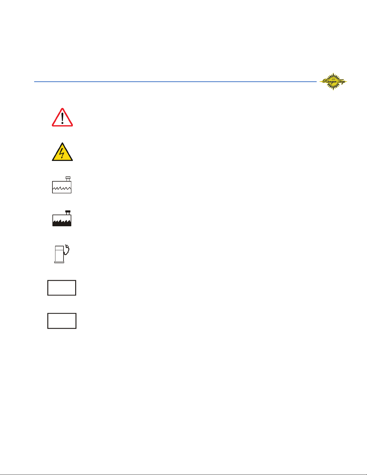
Symbol Glossary ........................................................................................................... 4
Specifications (Subject To Change Without Notice) ....................................................... 5
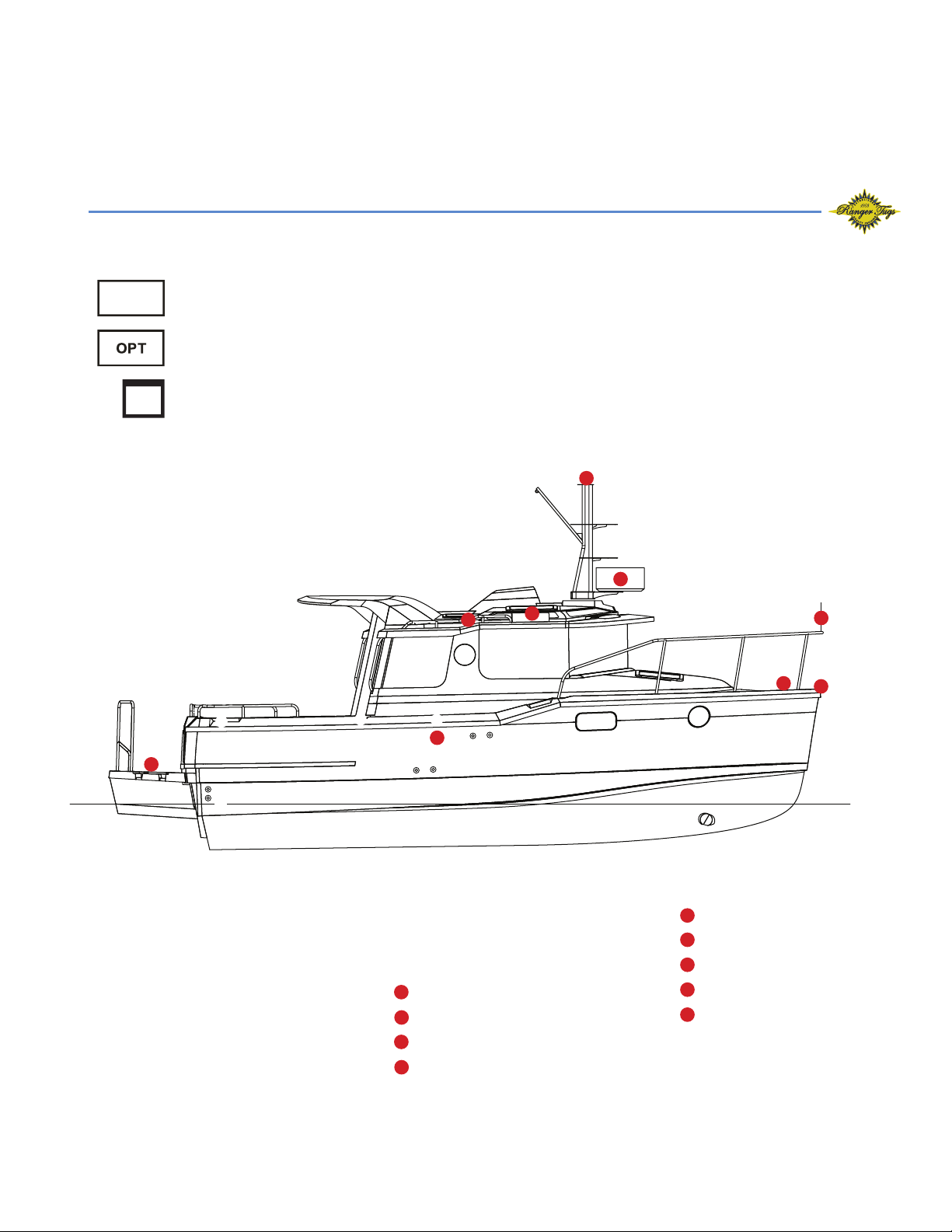
Equipment Location ..................................................................................................... 6
Starboard Fittings .................................................................................................. 6
Port Fittings ........................................................................................................... 7
Stern Components ................................................................................................ 8
Main Cabin And Cockpit Lights .............................................................................. 9
Fuel System, Engine, Generator ............................................................................. 10
Raw Water / Sea Strainer System ........................................................................... 11
Fresh Water Plumbing System ................................................................................ 12
Shower Sump ........................................................................................................ 13
Bilge Pump System ................................................................................................ 14
Waste System With Macerator Pump ..................................................................... 15
Air Conditioning ................................................................................................... 16
Webasto Furnace .................................................................................................. 17
Solar Panel ............................................................................................................ 18
Battery Configuration ............................................................................................ 19
Fuse Location & Values .......................................................................................... 20
Ac Distribution Panel & Rotary Switch .................................................................... 21
12V Helm Control Operation ................................................................................. 22
Ranger Tug R-23 Wiring Schematic (Acc. 1) ........................................................... 23
Ranger Tug R-23 Wiring Schematic (Acc. 2) ........................................................... 24
Ranger Tug R-23 Wiring Schematic (Acc. 3) ........................................................... 25
Ranger Tug R-23 Wiring Schematic (Lighting) ........................................................ 26
Ranger Tug R-23 Wiring Schematic (P.D.P.) ............................................................. 27
Ranger Tug R-23 Working Deck ................................................................................... 28
Care And Maintenance ................................................................................................ 29
Example Of A Preparation For The Road Checklist .................................................. 29
Example Of A Spring Pre-Launch Checklist ............................................................. 30
Example Of Winter Storage Checklist .................................................................... 31
Warning Label Locations .............................................................................................. 32

3
CONGRATULATIONS
The Ranger Tug family has a passion for boating. We are committed to continuous
process improvement in all areas that affect our customer’s satisfaction with our
products and providing great customer service.
SAFETY
Safety is always a priority at Ranger Tugs. Please read all manuals to ensure that
equipment is used in a safe manner. We highly recommend attendance in a Coast
Guard approved boating safety course. Such courses are available from the Coast
Guard directly or from boating organizations. Owners should have annual inspec-
tions to ensure that all safety equipment is current.
Operating, servicing and maintaining
a recreational marine vessel can expose
you to chemicals including engine exhaust,
carbon monoxide, phthalates, and lead,
which are known to the State of California
to cause cancer and birth defects or other
reproductive harm. To minimize exposure,
avoid breathing exhaust, service your vessel
in a well-ventilated area and wear gloves or
wash your hands frequently when servicing
this vessel. For more information go to
www.P65warnings.ca.gov/marine.
Prop 65 Boat Owner’s
Manual Image
Notes on use of the above:
27 CCR § 25607.18
§ 25607.18. Recreational Vessel Exposure Warnings -
Method of Transmission. [Operative August 30, 2018]
(a) A warning for exposures that occur during the operation
or maintenance of a recreational vessel as defined in California
Harbor and Navigation Code Section 651(t) meets the
requirements of this subarticle if it complies with the content
requirements in Section 25607.19 and is provided as follows:
(1) The warning is printed in the owner's manual for the
specific recreational vessel, in no smaller than 12-point type
enclosed in a box printed or affixed to the inside or outside
of the front or back cover of the manual or on the first page
of the text, and;
(2) The warning is provided on a hang tag readily visible from
the helm of the vessel printed in no smaller than 12-point type.

SYMBOL GLOSSARY
4
STE
OPT
Attention! – Important Operating or Maintenance Instructions
Attention! – Electrical Shock Hazard
Fresh Water
Black Water
Fuel
Standard Equipment
Optional Equipment
Hints

SPECIFICATIONS
5
(Subject to Change Without Notice)
R-23
Length (hull) ................................................................................. 22’ 8” 9.04 m
Length rigged (LOA) motor up ...................................................... 29’ 8” 9.04 m
Length rigged (LOA) motor down ................................................. 28’ 5” 8.66 m
Beam ............................................................................................ 8’ 6” 2.6 m
Draft (motor down) ....................................................................... 30” .76 m
Draft (motor up) ........................................................................... 19” .48 m
Height on trailer (w/radar) ............................................................. 11’ 4” 3.5 m
Height on trailer (no radar) ............................................................ 10’ 10” 3.3 m
Length on trailer motor up ............................................................ 36’ 10” 11.22 m
Length on trailer motor down ....................................................... 34’ 10” 10.61 m
Weight, dry ................................................................................... 5,000 lbs 2,268 kg
Bridge clearance (mast down) ....................................................... 8’ 6” 2.6 m
Fuel capacity ................................................................................. 80 U.S. Gal 302.8 L
Water capacity .............................................................................. 22 U.S. Gal 83.3 L
Holding tank capacity ................................................................... 11 U.S. Gal 41.6 L
Hot water tank ............................................................................. 4 U.S. Gal 15.14 L

EQUIPMENT LOCATION
6
STARBOARD FITTINGS
1 2 3 4 6 7 8 9 11 12 16
5 10 13 14
Keep all vents, drains and exhausts clear of any obstructions
to ensure proper performance of each system.
STE
➊ Fuel Fill
➋ Aft Bilge
➌ Forward Bilge
➍ Waste Pumpout
➎ Macerator Thru-Hull
➏ Galley Sink Drain
➐ Water Fill
➑ Water Tank Vent
➒ Waste Tank Vent
➓ Bow Thruster
Trailering Side Marker Light
Anchor Roller
Windlass
Radar
Anchor Light
Swim Ladder
Nav Light
Burgee Pole
VHF Antenna
➏➑➒
11
11
13
13 12
12
14
14
15
15
16
16
17
17
18
18
19
19
➎
➌
➋
➊
➓
➍➐

7
STE
PORT FITTINGS
1 2 3 4 5 6 7 8 9 14
2 3 10 11 12 13 14 15
Keep all vents, drains and exhausts clear of any obstructions
to ensure proper performance of each system.
➊ Anchor Locker Drain
➋ Bow Thruster
➌ Radar
➍ Nav Light
➎ Anchor Light
➏ Head Sink Drain
➐ AC Drain
➑ Shower Drain
➒ Trailering Side Marker Light
➓Generator Air Intake
Generator Exhaust
Bow Eye
Webasto Air Intake
Webasto Exhaust
Webasto Fuel Fill
➊
➋
➌
➍
➎
11
11
13
13
12
12
14
14
15
15
➏➐ ➒
➓
➑

8
STERN COMPONENTS
STE
1 2 3 4 6 8 10 11 12 13 15 16
➊ ➊
➋
➌ ➌
➍ ➍
➑
➒ ➒
➎➎
➏
➐
7 5 14
➊ Swim Platform Courtesy Lights
➋ Fuel Fill
➌ Cockpit Scupper Drains
➍ Trim Tabs
➎ Underwater Lights
➏ Drain Plug
➐ Multiport Strainer Exhaust
➑ Engine Pod Bilge Pump
➒ Trailer Turn/Brake Lights
➓ Rod Holders
Pod Drain Plug
Engine Well Drain
Flagstaff Mount
Trim Tab Zinc (behind lights)
Towing Strapdown
Trim Tab Ram
11
11
13
13
12
12
14
14 14
15
1515
16
16 16
➓

9
MAIN CABIN AND COCKPIT LIGHTS
STE
Switch on
fixture
Switch on
fixture
Switch on
fixture
V-Berth Lighting
(below seat in midberth)
Indirect LED
Lighting
Push On/Off
LED Lights Push On/Off
LED Lights
Indirect LED
Lighting
Cabin lighting
Courtesy / LED
Lights
Optional Underwater Lights

FUEL SYSTEM, GENERATOR
STE
Yamaha 200
Optional Fuel System
with Generator
Standard Fuel System
10
Generator
Fuel Tank
Primer bulb
Fuel fill
Sender
Vent
Vent
Fuel filter /
seperator
Fuel Tank
Generator
Fuel filter /
seperator
Generator
Fuel filter /
seperator
Primer bulb
Fuel fill
Sender
Vent
Vent
Generator
Supply

11
RAW WATER / SEA STRAINER SYSTEM
STE
• Multi port sea strainer for head and raw water wash down pump.
Marine Toilet
Generator
Multi Strainer
(optional)
Strainer Relief
Overflow Thru Hull
Raw Water Washdown
(standard)
Head Raw Water
Multi Strainer
Thru-hull/Valve
Raw Water Washdown
(standard)
Marine Toilet
AC Water Pump
(optional)
Head Raw Water
Sea Strainer
Thru-hull/Valves
Sea Strainers
• A/C Raw Water Input
• Generator raw water thru-hull strainer
Raw Water System with GeneratorRaw Water System

12
FRESH WATER PLUMBING SYSTEM
STE
22 Gallon Fresh Water Tank, 4 Gallon Hot Water Heater, 3.5 GPM Fresh Water Pump.
Disinfecting The Fresh Water System
Water fill
Water vent
Cabin sink
Water
Pump
Head
sink
Water heater
Water heater drain
Sender
H-23
7/14
© 2014 American Boat & Yacht Council, Inc.
6
APPENDIX - POTABLE WATER SYSTEMS
The information contained in this appendix provides supplementary data about disinfecting a potable water system.
A SUGGESTED METHOD OF DISINFECTION
Perform the following steps in the order indicated:
a. Flush entire system thoroughly by allowing potable water to flow through it;
b. Drain system completely;
c. Fill entire system with a chlorine solution having a strength of at least 100 parts per million, and allow to
stand for one (1) hour. Shorter periods will require greater concentrations of chlorine solution. See Table I
d. Drain chlorine solution from entire system;
e. Flush entire system thoroughly with potable water;
f. Fill system with potable water.
Table I shows how much disinfecting agent is required to make up various quantities of 100 parts per million chlorine
solution.
TABLE I – CHLORINE CONCENTRATIONS
Amount of chlorine compound required for 100 ppm solution
Solution
(Gallons)
Chlorinated Lime
25% (ounces)
High Test Calcium
Hypochlorite 70%
(ounces)
Liquid Sodium
Hypochlorite 1% (quarts)
5
0
.
3 0
.
1 0
.
2
10 0
.
6 0
.
2
0
.
4
1
5
0
.
9 0
.
3 0
.
6
2
0 1
.
2
0
.
4 0
.
8
30 1
.
8 0
.
6 1
.
2
5
0 3
.
0 1
.
0
2
.
0
100 6
.
0
2
.
0 4
.
0
NOTE: This table contains information taken from the Handbook on Sanitation of Vessel Water Points,
Public Health Service Publication No. 274 - Reprinted June 1963.
* * * * *
Origin and Development of ABYC H-23, Water Systems for Use on Boats
ABYC H-23, Installation of Potable Water Systems for Use on Boats was first published in 1970. Revised editions
were published in 1974, 1983, 1996, and 2008. In 2014 the title was revised to H-23, Water Systems for Use on
Boats. The 2014 version is the work of the Hull Piping Project Technical Committee.
* * * * *
ABYC technical board rules provide that all reports, including standards and technical information reports, are
advisory only. Their use is entirely voluntary. They represent, as of the date of publication, the consensus of
knowledgeable persons, currently active in the field of small craft, on performance objectives that contribute to small
boat safety.
The American Boat & Yacht Council assumes no responsibility whatsoever for the use of, or failure to use, standards
and technical information reports promulgated by it, their adaptation to any processes of a user, or any consequences
flowing therefrom.
Prospective users of the standards and technical information reports are responsible for protecting themselves
against liability for infringement of patents.
The American Boat and Yacht Council standards and technical information reports are guides to achieving a specific
level of design or performance, and are not intended to preclude attainment of desired results by other means.

SHOWER SUMP
13
STE
12V, 1000 GPH
(This should be inspected for debris on a regular basis if shower is used frequently.)
Shower drain
Thru-hull
Sump pump
Depth Transducer
The shower sump box is located underneath the removable v-berth step positioned just
outside the head door.

BILGE PUMP SYSTEM
14
Forward bilge pump
(1100 GPH)
Aft bilge pump
(1100 GPH)
Thru-hulls
Thru-hull
Pod bilge pump
(1100 GPH)
Pod bilge pump
switch
STE
The bilge pumps operate automatically by checking for water every 2.5 minutes even with
battery switches and breakers in the OFF position.
However, the bilge pumps will run continuously once their switches are placed in the on position.
Monitor the outflow accordingly. Do not run when dry.
• Manual switches are located at the helm for the forward and center pumps.
• The aft bilge pump switch is located in the aft section of the cockpit.
12V 1100GPH

WASTE SYSTEM WITH MACERATOR PUMP
STE
11 Gallon Tank with standard pump out, and vent
Waste tank pump out stations are widely available.
Please follow the directions carefully for the pump out equipment you are using to avoid damage
to the waste system.
Boat owner is responsible for following all applicable laws when using the macerator
system to pump out into the surrounding waters.
Overboard shutoff valve is accessed under the galley sink above the pump area.
Macerator pump out
15
Holding Tank
Waste pumpout
Macerator out
Macerator pump
Macerator
shut off
Waste vent

16
AIR CONDITIONING
AC Water Pump
Multi Strainer
Thru-hull/Valve
Multi Strainer
Main Cabin A/C Control
Panel (in Mid-Berth)
Main Cabin A/C Unit
(Under Seat)
A/C Vent

17
WEBASTO FURNACE
Webasto furnace is located under helm seat.
The control panel is located at the quarter berth power management center.
The fuel pump and filter are beneath the passenger seat, inside of the black box.
To access the heater/pump the seat must be removed. The fuel filter should be changed during
the annual maintenance. Filter change intervals may vary depending on usage.
Webasto Furnace
Diesel Tank (3.5 gal)
V-Berth Interior
Heat Vent
Main Cabin
Heat Vent
Exhaust
(keep unblocked/
gets very warm)
Air Intake
Pump/Filter

18
SOLAR PANEL
Solar panel 90 watt, with display panel
• The solar panel is designed to provide charging to the house & engine batteries. 90% of its
charge is dedicated to the house battery and 10% is dedicated to the engine battery.
• The green light on the solar display indicates proper operation.
• The solar display is located in the mid-berth.
• The controller is located in the lazarette
*Keep panel clean and completely uncovered for best results
• There is an inline fuse on top of the batteries for solar charging.
• The controller is located in the lazarette
*Keep panel clean and completely uncovered for best results
• There is an inline fuse on top of the batteries for solar charging.
Solar Panel
Display
Controller
Batteries
1
1
2
3
Battery Banks
1= House
2= Engine
3= Thruster (optional)

19
BATTERY CONFIGURATION
STE
2 House Batteries, 1 Engine Battery, 1 Thruster Battery (optional).
1
1
2 3
3 bank battery charger
Ground/bonding bus
Inverter battery switch
Inverter current breaker (200A)
Thruster battery switch (optional)
Thruster ANL fuse 200A (optional)
HOUSE
ENGINE
EMERGENCY
PARALLEL
STE
House, engine, & battery parallel switches are located in the midberth.
Thruster battery switch is located in the port side lazarette
Inverter battery switch and ANL fuse located in the port side lazarette
Once the EMERGENCY PARALLEL switch is placed in the on position the power from the
HOUSE batteries will be transferred to the ENGINE battery. Use only for EMERGENCY
starting of the engine.
If the house bank drops below 10.8v you must reset the charging relay by switching on
the parallel while the engine is running or while plugged into shore power.
Automatic Charging
Relay (ACR)
House Breaker
Automatic Charging
Relay (ACR)
Downrigger Starboard
Freshwater Switch
Downrigger Port
TV
Washdown Switch
Cabin Light
LED Light Switch
Fridge Foreward
Fridge Aft
Underwater Lights
USB V-Berth
USB Port
40
40
CO Monitor
Stereo Memory
Stove Switch
#1 Float
#2 Float
3 3
1
HOUSE
BREAKER
175
Battery Banks
1= House
2= Engine
3= Thruster (optional)

20
FUSE LOCATION & VALUESFUSE LOCATION & VALUES
STE
Dash fuse blocks are located behind a hinged access panel in the head. The 24/7 fuse block is
located in the mid cabin behind a removable panel secured with Velcro in the aft inboard corner.
Fuses are automotive blade type and all values shown below are in Amps.
* To reset, reinsert yellow
arm “up” into the breaker.
To test, press red button
and the yellow arm should
flip down.
Left Right
Trim Tab
Toilet
Switch Panel
12v Outlet
Bathroom
Reading Light
Bathroom Light
V Berth Light12v Outlet
Spot Light
Stereo
Shower Pump
4 SW Panel Power
GPS
8 SW Panel Power #2
8 SW Panel Power #1
NEMA
AIS
Bildge Pump
VHF
Auto Pilot 40
R-23
Fuse Block Layouts
Last Update:8/16/16
Dash Fuse Block #1
4SwitchPanel
8SwitchPanel
8SwitchPanel
Stereo
ShowerPump
T.V. #1 (Option)
HeaterCraft(Option)
VHF
Auto Pilot Pump
Trim Tab
Deck Lights
Misc Light Switch
Cabin Light Switch
V-Berth Light Switch
Refrigerator
F/W Switch
12V DC Port
12V DC Passenger
12V DC Starboard
Shower Pump
Fan Switch
8 Switch Panel Power
4 Switch Panel Power
NEMA
Garmin
Washdown Switch
Stereo
VHF
Trim Tab
Deck Lights
Misc Light Switch
Cabin Light Switch
V-Berth Light Switch
Refrigerator
F/W Switch
12V DC Port
12V DC Passenger
12V DC Starboard
Shower Pump
Fan Switch
8 Switch Panel Power
4 Switch Panel Power
NEMA
Garmin
Washdown Switch
Stereo
VHF
Autopilot
Table of contents
Other Rangertugs Boat manuals
Popular Boat manuals by other brands

Canadian Electric Boat Company
Canadian Electric Boat Company Fantail 217 owner's manual

Prestige
Prestige 500 user guide

BENETEAU
BENETEAU 323 2006 Information & operation manual

Sevylor
Sevylor YUKON KCC380 owner's manual

Falcon
Falcon F18 owner's manual

Polaris
Polaris msx 110 Owner's manual for maintenance and safety

Cruisers Yachts
Cruisers Yachts 420 Express Series owner's manual

Carver
Carver 56 Voyager SE Setup

Monterey
Monterey 295SY owner's manual

no stress yachting
no stress yachting BAVARIA 45 CRUISER instruction manual

Creek Company
Creek Company ODC 915 Assembly instructions

J&J Amusements
J&J Amusements 24v 1750 rpm Service manual