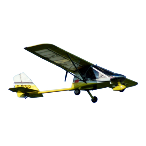
Rans S-7LS Courier Owner's manual

S-7LS COURIER
LIGHT SPORT AIRCRAFT
PILOT OPERATING HANDBOOK
Serial Number:
Registration Number:
March 3, 2005
COPYRIGHT © 2005
RANS DESIGNS
KANSAS, USA

Rans Inc.
Model S-7LS COURIER Table of Contents
Original Issue March 3, 2005 ii
TABLE OF CONTENTS
SECTION
GENERAL INFORMATION …………………………………… 1
OPERATING LIMITATIONS……………………………………. 2
WEIGHT AND BALANCE INFORMATION …………………… 3
PERFORMANCE ………………………………………………… 4
EMERGENCY PROCEDURES ………………………………… 5
NORMAL PROCEDURES ……………………………………… 6
AIRCRAFT GROUND HANDLING AND SERVICING … 7
REQUIRED PLACARDS AND MARKINGS …………………. 8
SUPPLEMENTARY INFORMATION……… …………………. 9

Rans Inc. Section 1
Model S-7LS COURIER General Information
Revision - B May 8, 2007 1- 1
SECTION 1
GENERAL INFORMATION
TABLE OF CONTENTS
Page
Three View………………………………………………………………………………. 1-3
Introduction………………………………………………………………………………. 1-4
Airplane and Systems Descriptions…………………………………………………… 1-4
Airframe………………………………………………………………………… 1-4
Flight Controls…………………………………………………………………. 1-4
Trim Control System………………………………………………………….. 1-5
Wing Flap System…………………………………………………………….. 1-5
Landing Gear………………………………………………………………….. 1-5
Seats……………………………………………………………………………. 1-5
Seat Belts and Shoulder Harness…………………………………………… 1-6
Powerplant…………………………………………………………………….. 1-6
Carburetors and Fuel Pumps………………………………………………… 1-6
Exhaust System……………………………………………………………….. 1-6
Oil System……………………………………………………………………… 1-7
Liquid Cooling System………………………………………………………… 1-7
Carburetor Heat……………………………………………………………….. 1-7
Propeller………………………………………………………………………… 1-9
Fuel System……………………………………………………………………. 1-10
Brake System………………………………………………………………….. 1-13
Doors……………………………………………………………………………. 1-13
Electrical System………………………………………………………………. 1-13
Pitot and Static System………………………………………………………... 1-14
Instrument Panel……………………………………………………………….. 1-14
Engine Instruments……………………………………………………. 1-14
Flight Instruments……………………………………………………… 1-14

Rans Inc. Section 1
Model S-7LS COURIER General Information
Revision - B May 8, 2007 1- 2
Operating Weights and Loadings ………………………………………………….. 1-16
Maximum Airplane Weights …………………………………………………. 1-16
Standard Airplane Weights …………………………………………………… 1-16
Cabin and Entry Dimensions ………………………………………………… 1-16
Specific Loadings……………………………………………………………… 1-16
Symbols, Abbreviations and Terminology …………………………………………… 1-16
General Airspeed Terminology and Symbols ……………………………… 1-17
Meteorological Terminology …………… …………………………………… 1-17
Engine Power Terminology …………………………………………………. 1-18
Airplane Performance and Flight Planning Terminology ………………… 1-18
Weight and Balance Terminology …………………………………………… 1-18

Rans Inc. Section 1
Model S-7LS COURIER General Information
Revision - B May 8, 2007 1- 3
THREE VIEW

Rans Inc. Section 1
Model S-7LS COURIER General Information
Revision - B May 8, 2007 1- 4
INTRODUCTION
This handbook contains 8 sections.
The pilot should study the entire handbook to familiarize himself with the limitations,
performance and procedures applicable for this aircraft.
Section 1 provides general information and system descriptions.
AIRPLANE AND SYSTEMS DESCRIPTIONS
AIRFRAME
The primary airframe construction material is tubular aircraft grade aluminum and steel.
Primary items of the structure are the fuselage and tail structure. The fuselage and tail
structure are of steel truss construction. The flight controls, main wheels, and seats are
attached to the forward part of the fuselage. The empennage (tail assembly) is attached
to the aft section of the tail structure. The fuselage and tail structure are covered with
polyester fabric type covering.
The externally braced wings are comprised of a tubular leading edge and trailing edge
spar joined by compression and diagonal struts. Formed ribs maintain the airfoil shape.
The leading edge and trailing edge spars are equipped with strut attachment fittings.
Conventional hinged ailerons are attached to the outboard section of the trailing edge
spar of the wings. Conventional flaps are attached to the inboard section of the trailing
edge spar of the wings. The wing, ailerons and flaps are covered with polyester fabric
type covering.
The tail assembly consists of a conventional vertical stabilizer, horizontal stabilizer,
rudder, and elevator. The stabilizers are braced with stainless steel rods. The right
elevator carries a servo- adjustable trim tab. The left elevator has a fixed stability tab (do
not adjust). The tail assembly is covered with polyester fabric type covering.
FLIGHT CONTROLS
The aircraft's flight control system consists of conventional aileron, rudder, and elevator
control surfaces.
The ailerons are manually operated through cables to bell cranks in each wing and short
push pull tubes from bell crank to aileron.
The elevators are operated through push pull tubes via a bell crank.
The forward and rear rudder pedals are connected through link tubes and the rear
pedals via cables to the rudder. By pushing the left rudder pedal the aircraft yaws to the
left and the right pedal yaws the aircraft to the right. All flight control surfaces are of
tubular construction with fabric covering.
The aircraft has the following controls at both seats.
-Control sticks

Rans Inc. Section 1
Model S-7LS COURIER General Information
Revision - B May 8, 2007 1- 5
-Rudder pedals
-Brake pedals
-Throttle lever
TRIM CONTROL SYSTEM
The AC has an in flight elevator trim system.
The movable trim tab is operated through a servomotor installed in the right elevator via
a short pushrod.
The trim switch for nose up and nose down trim are located at the top of the forward
control stick. An Indicator installed in the instrument panel provides information about the
position of the trim tab.
WING FLAP SYSTEM
The flaps are conventional plain flaps and are extended or retracted by positioning the
flap selector lever (located on the left side of the forward control stick) to the desired flap
deflection position. The spring loaded flap lever moves up or down parallel to metal
plates that provide indentations creating mechanical stops at the desired flap position.
The flap lever has a button on the top. This button must be pushed slightly before
moving the flap lever into a new position. The Lever has a “flaps retracted”, “flaps half”,
and “flaps full” position. The flaps are retracted when the lever is all the way down and
the flaps are full down when the flap lever is all the way up. When the new flap position
is reached, ensure that the lever is securely seated in the new position.
The flaps are actuated through Teleflex- cables (push pull cable). A slight play on the
trailing edge (up and down) is normal.
LANDING GEAR
The landing gear is of the tail dragger type, having a steerable tail wheel and two main
wheels. Shock absorption is provided by the tapered, heat- treated, alloy steel main
landing gear legs and a steel heat- treated flat spring for the tail wheel. The tail wheel is
connected via springs to the rudder and is steerable through the rudder pedals.
The full swivel tail wheel can be made to swivel by using full rudder pedal and brakes in
the desired direction to turn. The steer-cam disengages once the rudder and brakes
have turned the tail wheel to almost max travel left or right. To re-engage steering use
brakes and rudder to taxi a few feet straight.
SEATS
The AC is flown from the front seat if solo.
Both seats are attached to the forward fuselage tube frame by adjustable seat rails.
They are adjustable fore and aft. Each seat is adjusted through removing of the locking
pins, readjusting the seat position as desired and re installation of the locking pins (2 per
seat). The seats can only get adjusted if not occupied. Do not attempt in flight.

Rans Inc. Section 1
Model S-7LS COURIER General Information
Revision - B May 8, 2007 1- 6
SEAT BELTS AND SHOULDER HARNESSES
The aircraft is equipped with a four-point pilot restraint system. At any time the pilot is
seated in the aircraft with the intent of moving it, the pilot restraint system must be
securely fastened. Always ensure the buckle is snapped into its locking position and the
belt tension is snug and the shoulder harness are placed over the shoulders and
properly adjusted. The empty seat restraint system must be secured even when not
in use. NOTE: Always ensure the pilot restraint systems are not restricting any control
system movement.
POWERPLANT
The S-7LS is powered by a Rotax four stroke, four cylinder horizontally opposed engine.
The cylinders are ram air-cooled and the cylinder heads are water- cooled. The ignition
is of the electronic type.
The propeller is driven via a reduction gear. The RPM indicated is engine- RPM. The
engine is started through an electrical starter.
Number of Engines: 1
Engine Manufacturer: Rotax
Engine Model Number: 912 ULS
Engine type: Normally aspirated, four stroke, horizontal opposed, gear
drive, liquid cooled cyl.- heads, air cooled cyl., carburetor
equipped four cylinder engine with 1352 cm³(82.5in³)
displacement.
Horsepower rating and
Engine speed:
Maximum Takeoff (max off 5 min): 98.5 HP at 5800 RPM
Max. Continuous : 92.5 HP at 5500 RPM
Idle (aprox.): 1400 RPM
CARBURETORS AND FUEL PUMPS
Two Bing carburetors with float chambers are used on the Rotax engine.
An engine driven fuel pump supplies fuel to both carburetors. A electrical back up fuel
pump (fire wall mounted) is used during take off, climb out, landing and in case of engine
pump failure.
A separate air filter is attached to each carburetor.
EXHAUST SYSTEM
The exhaust system consists of an after muffler and four pipes made from stainless
steel. A stainless steel wrap around the muffler provides cabin heat and heat cups
attached to both sides of the muffler canister provide heated air for the carburetor heat.

Rans Inc. Section 1
Model S-7LS COURIER General Information
Revision - B May 8, 2007 1- 7
OIL SYSTEM
The engine is equipped with a dry sump forced lubrication system with a main oil pump
with integrated pressure regulator and oil pressure sensor. The oil pump sucks the oil
from the oil tank via the oil cooler and forces it through the oil filter to the points of
lubrication of the engine.
Oil Grade: SAE Motorcycle oil of registered brand with gear additives.
Use only oil with API classification “SF” or “SG”. Minimum
recommended viscosity 10W-40.
For additional information refer to ROTAX Operators - and
Maintenance Manual.
►CAUTION: Do not use aircraft engine oil
Total Oil Capacity: 6.4 liq pt ; minimum 4.2 liq pt.
LIQUID COOLING SYSTEM
The cooling system of the cylinder heads is a closed circuit with an expansion tank.
The coolant flow is forced by a water pump from the radiator to the cylinder heads and to
an expansion tank on top of the engine. The expansion tank is closed by pressure cap.
An overflow bottle receives coolant by temperature rise. The radiator is located at the
bottom of the cowling inside the engine compartment.
Coolant capacity: 2.5 qt.
For additional information refer to ROTAX- Operators and Maintenance Manual.

Rans Inc. Section 1
Model S-7LS COURIER General Information
Revision - B May 8, 2007 1- 8
CARBURATOR HEAT
Each one of the two carburetors of the Rotax 912S engine has a separate pre heating
system consisting of a heat exchanger, heat control unit and connecting duct hose. One
control knob operates both systems. Figure 1- 1 shows the general layout of the design
(only the left side is shown).
Figure 1-1. Carburetor Heat
A heat exchanger is mounted to both sides of the exhaust muffler. The air entering the
carburetor (heat on selected) is downstream cooling air, which is further heated on the
sides of the exhaust muffler when passing through the heat exchanger.
The sides of the exhaust muffler provide sufficient area for heat transfer. Figure 1- 2
shows the muffler mounted heat exchanger.
Figure 1-2. Carburetor Heat Exchanger

Rans Inc. Section 1
Model S-7LS COURIER General Information
Revision - B May 8, 2007 1- 9
The instrument panel mounted control knob opens or closes the valves in both heat
control units with a simple mixer simultaneously. The position of the valve determines if
the engine runs on “cool” air coming through the air filter or on “hot” unfiltered air coming
from the heat exchanger.
A spring mounted to each control unit supports the closing of the heat control valve and
assures a fully closed valve when carburetor heat “off “is selected and therefore cool air
supply and maximum engine performance. Reference also Figure 1-3.
Figure 1-3. Carburetor Heat Valve

Rans Inc. Section 1
Model S-7LS COURIER General Information
Revision - B May 8, 2007 1- 10
PROPELLER
The propeller is a fixed pitch Sensenich wood propeller. The maximum diameter is 72".
The propeller has a polyurethane leading edge for protection and better service life.
Always park the aircraft with propeller blades horizontal to preserve balance.
Propeller Manufacturer: Sensenich wood propeller Inc.
Propeller Model Number: W72RR
Number of Blades: 2
Propeller Diameter: 72”
Propeller Type: 2 blade, fixed pitch
Optional a 2 blade ground adjustable carbon propeller is installed (Sensenich).
Propeller Manufacturer: Sensenich wood propeller Inc.
Propeller Model Number: R70D
Number of Blades: 2
Propeller Diameter: 70”
Propeller Type: 2 blade, ground adjustable
FUEL SYSTEM
The S-7LS fuel system is a pump fed carbureted system incorporating two wing tanks ( 9
gallons each) interconnected at one fuel valve accessible to the primary occupant (front
seat).
Fuel quantity indication is provided through a fuel side gauge (clear plastic fuel line) at
each fuel tank.
The indicator is calibrated to read zero, when the unusable fuel amount of 1.25 gall
total or 0.625 gall each tank is reached in horizontal level flight at maximum
continuous RPM.
The ¼; ½; and ¾ marks are also with reference to level flight.
The 1 or full mark indicates a recommended refuel level, if the aircraft is to be parked
(sufficient expansion space) and is with reference to the ground attitude.

Rans Inc. Section 1
Model S-7LS COURIER General Information
Revision - B May 8, 2007 1- 11
Figure 1-4.Fuel system Airframe

Rans Inc. Section 1
Model S-7LS COURIER General Information
Revision - B May 8, 2007 1- 12
In addition to the engine mounted (mechanical) fuel pump, there is an electric (back up)
fuel pump mounted to the aft engine mount. These pumps are fed from a gascolator
mounted on the firewall. This system incorporates an anti vapor lock feature at the fuel
tee between the carburetors that feeds the vapor back to the gascolator at the firewall.
Figure 1-5 Fuel System Engine
The system also incorporates a panel mounted fuel pressure gauge

Rans Inc. Section 1
Model S-7LS COURIER General Information
Revision - B May 8, 2007 1- 13
Fuel Grade: unleaded automotive (ASTM D 4814) gasoline with
minimum AKI (Anti Knock Index) of 91 (R+M)/2 –
No alcohol permitted.
Or AVGAS 100 LL
For additional information refer to ROTAX Operators - and
Maintenance Manual
►ATTENTION: If engine is mainly run on AVGAS
more frequent oil changes will be required.
For additional information refer to ROTAX
Operators - and Maintenance Manual
Fuel Capacity:
Total Capacity: 18 US Gal.
Total Capacity each tank: 9 US Gal.
Total Usable: 16.75 US Gal.
►NOTE: Due to cross feeding between fuel tanks,
the tanks should be re- topped after each refueling
to assure maximum capacity.
BRAKE SYSTEM
The S-7LS is equipped with a main wheel hydraulic braking system. The brake pedals
are mounted on top of the forward and rear rudder pedals. The individual brake pedals
allow differential braking of left or right wheel. Pushing both pedals will result in braking
on both wheels.
The braking system is equipped with a hydraulic fluid reservoir located firewall forward.
Check the fluid level frequently.
To activate the park brake, push both brake pedals and pull the park brake knob on the
left side of the instrument panel. To deactivate the park brake, push the park brake knob
in. Always make sure, that the park brake is off, before adding power for taxiing or at
landing.
DOORS
The S-7LS is equipped with two doors, one on each side of the AC. Always secure the
doors before flight. Only 1 door may be open in flight. Open at or below 60 mph. Do not
exceed 100 mph.
If a door comes open in flight, fly the AC before you attempt to close it. The AC will fly
with open doors. The door will float in a position pending on the speed of the AC. To
close an open door in flight, slow to 60 mph, push the opposite rudder pedal. This will
make the AC yaw and help to get the door closed.

Rans Inc. Section 1
Model S-7LS COURIER General Information
Revision - B May 8, 2007 1- 14
ELECTRICAL SYSTEM
The S-7LS electrical system is a 12-volt negative ground system. An integral AC
generator mounted in the aft end of the engine powers it. It stores energy in a sealed
maintenance free battery, located in the tail cone. Power is regulated by a solid-state
regulator-rectifier located on the firewall.
Charge or discharge of the battery is indicated at a panel -mounted voltmeter.
PITOT AND STATIC SYSTEM
The S-7LS incorporates both pitot and static sources on the same probe. The probe
extends forward of the left wing. The probe is attached to the instruments with plastic
line joined with quick connectors.
INSTRUMENT PANEL
Engine Instruments
The aircraft is equipped with a tachometer, engine oil temperature gauge, engine oil
pressure gauge, cylinder head temperature gauge, fuel pressure gauge, voltmeter and
an hour meter. The cylinder head temperature gauge is used to monitor the coolant
temperature also.
Flight Instruments
The AC is equipped with airspeed indicator, vertical speed indicator, altimeter, slip
indicator, and compass.

Rans Inc. Section 1
Model S-7LS COURIER General Information
Revision - B May 8, 2007 1- 15
1 Engine Choke Control 17 Outside Air Temperature Gauge
2 Carburetor Heat Control 18 Hour Meter
3 Cabin Heat Control 19 Fuel Pressure Gauge
4 Park Brake Control 20 Voltmeter
5 Intercom 21 Tachometer RPM- Gauge
6 Air Speed Indicator 22 Transponder
7 ELT Remote Control 23 Radio/ GPS Combination
8 Trim Position Indicator 24 Master Switch
9 Vertical Speed Indicator 25 Fuel Pump Switch
10 Slip Indicator 26 Avionics Master Switch
11 Altimeter 27 Ignition Key Switch
12 Music In (Plug) 28 Trim Switch Elevator Trim “Nose UP”
13 Emergency Head Set Plug In 29 Trim Switch Elevator Trim “Nose Down”
14 Oil Pressure Gauge 30 Push to Talk Switch (Radio)
15 Cylinder Head Temperature Gauge 31 Remote Frequency Select Switch
16 Oil Temperature Gauge 32 Compass
33 Fuel Main Shut Off Valve (Floor Board)
Figure 1- 6 Instrument Panel
CARB HEAT
CHOKE PULL
PULL ON
ON ON
FUEL
PUMP
AVIONICS
MASTER
ON
MASTER
RADIO/GPSTRANSPO.INTERCOM
REG.
OUTPUT
ENG. INSTR. TRIM STARTER REGULATOR
OPEN
SPINS PROHIBITED
ELT
CABIN HEAT
PULL ON
PARKING
PULL SET
DOWN
UP
T.O.
BRAKE
MUSIC IN
EMRG. COM
OIL PRESS. OIL TEMP.
CHT OAT

Rans Inc. Section 1
Model S-7LS COURIER General Information
Revision - B May 8, 2007 1- 16
OPERATING WEIGHTS AND LOADINGS
MAXIMUM AIRPLANE WEIGHTS
Ramp: 1235 lb.
Takeoff: 1235 lb.
Landing: 1235 lb.
Weight in Baggage Compartment: 50 lb.
STANDARD AIRPLANE WEIGHTS
Standard Empty eight: 740 lb.
Maximum Useful load: 495 lb.
CABIN AND ENTRY DIMENSIONS
Cabin width (Maximum) 27 “
SPECIFIC LOADINGS
At Maximum Takeoff weight:
Wing Loading: 8.16 lb./ft²
Power Loading: 12.18 lb./ HP

Rans Inc. Section 1
Model S-7LS COURIER General Information
Revision - B May 8, 2007 1- 17
SYMBOLS, ABBREVIATIONS AND TERMINOLOGY
The following definitions are of symbols, abbreviations and terminology used in this
handbook and which may be of operational significance to the pilot.
GENERAL AIRSPEED TERMINOLOGY AND SYMBOLS
CAS Calibrated Airspeed is indicated airspeed corrected for position
and instrument error.
IAS Indicated Airspeed is the speed shown on the airspeed indicator.
TAS True Airspeed is the airspeed relative to undisturbed air which is
CAS corrected for altitude and temperature.
VA Maneuvering Speed is the maximum speed at which full or abrupt
control movements may be used.
VFE Maximum Flap Extended Speed is the highest speed permissible
with wing flaps in a prescribed extended position.
VNO Maximum Structural Cruising speed is the speed that should not
be exceeded except in smooth air and then only with caution.
VNE Never Exceed Speed is the speed limit that may not be exceeded
at any time.
VS Stalling Speed or the minimum steady flight speed at which the
airplane is controllable.
VSO Stalling Speed or the minimum steady flight speed at which the
airplane is controllable in the landing configuration.
VX Best Angle off Climb Speed is the airspeed, which delivers the
greatest gain of altitude in a given horizontal distance.
VY Best Rate off Climb Speed is the airspeed, which results in the
greatest gain of altitude in a given time.

Rans Inc. Section 1
Model S-7LS COURIER General Information
Revision - B May 8, 2007 1- 18
METEOROLOGICAL TERMINOLOGY
OAT Outside Air Temperature is the free air static temperature
STANDARD
TEMPERATURE Standard Temperature is 15 ° C at sea level and decreases
approximately 2° C for each 1000 ft of altitude.
PRESSURE
ALTITUDE Pressure Altitude is the altitude read from an altimeter when the
barometric scale has been set to 29.92 inches of mercury (1013
mb).
ENGINE POWER TERMINOLOGY
BHP Brake Horsepower is the power developed by the engine.
RPM Revolutions per Minute is the engine speed
STATIC RPM Static RPM is engine speed attained during a full throttle engine
run up with the airplane on the ground and stationary.
MAXIMUM
CONTINUOUS
POWER Maximum power permissible continuously during flight.
AIRPLANE PERFORMANCE AND FLIGHT PLANNING TERMINOLOGY
DEMONSTRATED
CROSSWIND
VELOCITY The Demonstrated Crosswind Velocity is the velocity of the
crosswind component for which adequate control of the airplane
during takeoff and landing was actually demonstrated during
certification flight test.
USABLE FUEL Usable Fuel is the fuel available for flight planning
UNUSABLE FUEL Unusable Fuel is the quantity of fuel that can not be safely used
during flight.
GPH Gallons per Hour is the amount of fuel consumed per hour.
Table of contents
Other Rans Aircraft manuals

Rans
Rans S-21 OUTBOUND User manual

Rans
Rans S-21 OUTBOUND User manual

Rans
Rans N512DT User manual

Rans
Rans S-7S COURIER User manual

Rans
Rans S-12 User manual

Rans
Rans S-12 User manual

Rans
Rans S-20 RAVEN User manual

Rans
Rans S-19 VENTERRA User manual

Rans
Rans S-21 OUTBOUND User manual

Rans
Rans S-12 Owner's manual
Popular Aircraft manuals by other brands

ICARO paragliders
ICARO paragliders SPEEDUP manual

Zlin Aviation
Zlin Aviation Savage Cub 912 100 hp Flight manual

AMD
AMD Zodiac 601XL SLSA Maintenance manual

SOL paragliders
SOL paragliders ELLUS 2 Pilot's manual

Air Creation
Air Creation GTE 503 SE Instruction and maintenance handbook

Air Creation
Air Creation Skypper 582 S Maintenance manual