Ransomes 1200 Series User manual

RANSOMES
Parts & Fitting Instructions
Consignes relatives à la pose des composants
Onderdelen & Montagevoorschriften
Bauteilverzeichnis und Montageanleitung
Istruzioni per il montaggio di accessori e ricambi
Tilbehørs- og monterings-vejledning
Delar & instruktioner för montering
Osia ja varustuksia koskevia ohjeita
Instrucciones sobre Piezas y Accesorios
Instruções Peças e Acessórios
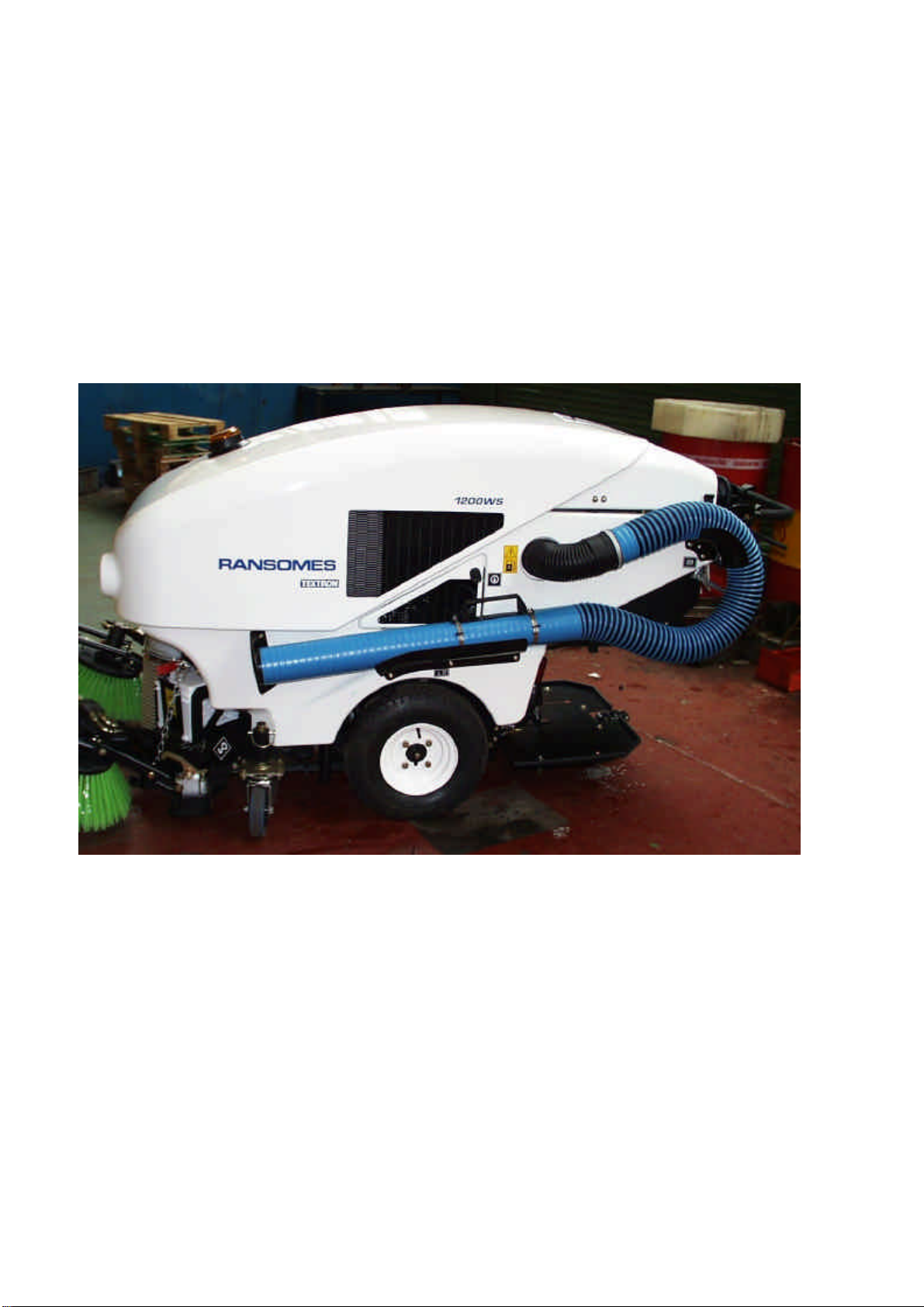
Wanderhose Kit for Ransomes Pathway 1200 series WE
Product code: LMAB637
RANSOMES
AVVERTENZA: Questa macchina può causare gravi infortuni
se viene utilizzata in modo errato. Prima di accingersi ad
approntare, usare, mettere a punto o eseguire la
manutenzione di questa macchina, coloro che la utilizzano
ediresponsabilidella manutenzionedevonoessereaddestrati
all’impiego della macchina, devono essere informati dei
pericoli, e devono leggere l’intero manuale.
GB
Part No. 24310G (rev.0)(RJ 100 062000)
FNL DI
WARNHINWEIS: Wenn diese Maschine nicht
ordnungsgemäß verwendet wird, können ernsthafte
Verletzungen verursacht werden. Personen, die diese
Maschine verwenden und warten, müssen in ihrer richtigen
Verwendung ausgebildet sein, auf die Gefahren aufmerksam
gemachtworden sein und dieAnleitung ganz gelesenhaben,
bevorsie versuchen, die Maschine aufzustellen, zu bedienen,
einzustellen oder zu warten.
WAARSCHUWING: Bij verkeerd gebruik kan deze machine
ernstig lichamelijk letsel veroorzaken. Degenen die de ma-
chine gebruiken en onderhouden moeten worden getraind in
het juiste gebruik ervan, worden gewaarschuwd voor de
gevarenervanenbehorendevolledigehandleidingaandachtig
te lezen alvorens de machine bedrijfs-klaar te maken, te
bedienen, af te stellen en/of te onderhouden.
AVERTISSEMENT : Risque de blessures graves en cas
d’utilisation incorrecte de la machine. Les opérateurs et le
personnel d’entretien doivent être formés et conscients des
dangers encourus. Ils doivent lire avec attention le manuel
avant d’essayer de monter, d’utiliser, de régler ou maintenir
la machine.
WARNING: If incorrectly used this machine can cause se-
vereinjury. Those who use and maintain this machine should
be trained in its proper use, warned of its dangers and should
read the entire manual before attempting to set up, operate,
adjust or service the machine.
DK SSF E P
AVISO: Esta máquina pode causar ferimentos graves se
for utilizada incorrectamente. A pessoa responsável pela
suautilizaçãoe manutenção deve ser previamente instruída
para a sua utilização correcta, avisada sobre os perigos
que ela pode causar e deve ler todo o manual antes de
tentar preparar, conduzir, afinar ou reparar a máquina.
ADVERTENCIA: Si se usa de forma incorrecta esta
máquina puede causar graves lesiones. Cualquier per-
sona que use y mantenga esta máquina deberá estar
entrenado en su uso correcto, instruido de sus peligro y
deberá leer el manual completamente antes de tratar de
instalar, operar, ajustar o revisar la máquina.
VAROITUS: Laitteen virheellinen käyttö voi aiheuttaa
vakavia vahinkoja. Laitteen käyttäjille ja huoltajille on
opetettava laitteen asianmukainen käyttö, heitä on varoitet-
tava mahdollisista vaaroista ja heidän on luettava koko
käyttöopas ennen laitteen valmistelua, käyttöä, säätämistä
ja huoltamista.
VARNING: Om denna maskin används på fel sätt kan den
orsaka svåra personskador. De som använder och
underhåller denna maskin ska utbildas i hur den används
korrekt, vara varnade för de förekommande riskerna och
ska alltid läsa hela handboken innan någon form av arbete
utförs på eller med maskinen.
ADVARSEL: Denne maskine kan forårsage alvorlig
personskade, hvis den bruges forkert. Alle, der bruger og
vedligeholder denne maskine, skal være korrekt uddannet
til dette, skal advares om farerne og læse hele
instruktionsbogen, før maskinen forberedes, bruges,
justeres eller serviceres.
®

©2000, Textron Inc. All Rights Reserved

GB-1
NOTICE
NOTICE
INSTALLATION INSTRUCTIONS
IMPORTANT!
Read all instructions thoroughly before beginning installation. When you complete the installation, put this
instruction with operator’s manual in the bag on the vehicle. These instructions alert you to certain things you
should do very carefully, if you don’t, you could: hurt yourself or bystanders, hurt the next person who operates
the equipment, or damage the accessory or the vehicle it is used on.
This “HAZARD” symbol is used to alert you to information about unsafe actions or situations, and will
be followed by the word DANGER, WARNING, or CAUTION. Used withthe word DANGER itwill describe
immediate hazards that may result in severe personal injury or death. With the word WARNING it will describe
unsafe actions or situations that may cause severe injury, death and/or major equipment or property damage.
With the word CAUTION it will describe unsafe actions or situations that may cause injury, and/or minor
equipmentorpropertydamage.
This NOTICE symbol is used to alert you to information that describes procedures or tips that will
help you install, operate and maintain you equipment.
WANDERHOSE KIT PARTS AND FITTING INSTRUCTIONS
PART No. LMAB637
FOR PATHWAY 1200WS
•Before beginning, read through this instruction manual and familiarise yourself with all the
parts in the Fitting Kit and the steps for proper installation.
•The left or right side or the machine will always be determined from the operaterating
position.

GB-2
TRIMMINGOF LEFTHAND SIDECOVER: 009135270.
a) Removethe sidepanel from theSweeper byundoing thefive screws:one onthe front, onebehind
the Access Panel, one behind the wheel and two at the rear of the machine, covered by the
Bonnet.
b) Carefully measure and mark the hole positions as detailed below. All holes to be drilled to Ø9mm
Eye protection should always be worn when
using power tools.
CAUTION

GB-3
c) Once drilled, bolt on the support pieces as supplied using large washers on both sides to ensure
the bolts do not pull through the GRP
009135370
009135360
009135350

GB-4
WORKINGONTHE FILTERCHAMBER, 009135190
a) With the side cover removed trim 10mm off the end of the boss as detailed in the following
diagram. This equates to the end of the radius.
Do not cut too much away as the hose
attaches to the straight section of the boss
CAUTION
b) Make sure that the hole has smooth edges so that the litter will not snag and block the hose
TRIM ALONG THIS END OF THE RADIUS

GB-5
FITTINGTHEHANDLETOTHEHOSE
a) Screw the plastic handle to the steel plate as shown
b) For general purposes the handle should be positioned at the top of the smooth duct section and
secured using the two Jubilee clamps, one at each end.

GB-6
FINALFITTING
a) Feed the flexible end of the Wanderhosethrough the hole inthe side cover
b) Pushthe flexible endof the Wanderhose over the trimmed boss on the filter chamber
c) Use the Band Clamp supplied to secure the Wanderhose to the boss. Ensure that it is a tight to
stop any leaks that would cause a drop in suction performance.
d) Reposition the side cover on the machine and secure.

GB-7
NOTICE HINTSON USEOFWANDERHOSE
If the Wanderhose is removed from its’ mount only 50% of suction will be available.
To obtain 100% suction on the hose take the blanking plate from its’ stowage position, hooked
underneath the Instrument Panel. Slide into place in the front of the Suction Head. This blocks air flow
throughthe Suction Headand allows fullsuction through theWanderhose.
When not in use, make sure that the hose is firmly seated and properly blocked by the support cap.
If not properly seated there will be a loss of suction performance.
BLANKING PLATE .


F-1
CONSIGNES RELATIVES A LA POSE DES
COMPOSANTS
IMPORTANT
Il faut lire entièrement les consignes avant de procéder à tout montage. Dès le montage terminé, replacez-les
dansleur casier.Les consignes voussignalent lesdangers éventuelsencourus etdoivent être respectéesafin
d’évitertoutrisquedeblessure pouvantaffecter nonseulement l’opérateurmais égalementlestiers,
endommagerles accessoires oula machine.
Le symbole“HAZARD” signale toute action ou situation dangereuse et précède le mot DANGER,
AVERTISSEMENT, ouATTENTION. Quandilest accompagnédumotDANGER il indiquedesrisques
immédiatspouvant s’avérer mortelsou desblessuresgraves. Quandilest accompagnédumot
AVERTISSEMENT ilindiquedesactionsousituationsdangereusespourvants’avérermortellesoublesser
gravement et/ou endommager la machineet les biens. Accompagnédu mot ATTENTION ilindique des actions
ou situations dangereuses susceptibles de blesser et/ou endommager légèrement la machine et les biens.
Le symbole CONSIGNE indiqueles procéduresou conseilsformulés, susceptiblesde vous
aideràmonter, fairefonctionnerouentretenir lescomposants.
CONSIGNES RELATIVES AUX COMPOSANTS DU KIT DU TUYAU BALADEUR ET A
LEUR POSE
No. PIECE LMAB637
MODELE PATHWAY 1200WS
•Lisez, tout d’abord, attentivement ces consignes et familiarisez-vous avec les composants
du kit et leur processus de pose.
•Le côté gauche ou droit de la machine est celui correspondant à l’opérateur en position de
conduite.
CONSIGNE
CONSIGNE

F-2
TAILLAGEDUCAPOTGAUCHE:009135270.
a) Déposez le panneau latéral de la balayeuse en dévissant les cinq vis suivantes : celle de
l’avant, celle derrière le panneau d’accès, celle derrière la roue et les deux vis à l’arrière de la
machine,recouvertes par lecapot.
b) Mesurez attentivement et placez des points de repère aux endroits où se trouvent les orifices.
Les orifices doivent tous être percés et avoir un diamètre de 9 mm.
Il faut toujours se protéger les yeux quand
desoutilsélectriquessontutilisés.
ATTENTION

F-3
c) Les orifices étant percés, boulonnez les supports fournis et placez des rondelles, des deux
côtés, afin que les boulons ne ressortent pas du plastique renforcé.
009135370
009135360
009135350

F-4
CHAMBREDEFILTRE, 009135190
a) Le panneau latéral étant retiré, taillez 10 mm sur l’extrémité du renflement, comme représenté
sur le schéma suivant, pour être égal à l’extrémité de l’arrondi.
Ne pas trop tailler car le flexible s’attache à
la partie droite du renflement.
ATTENTION
b) Veillez à ce que les bords de l’orifice restent lisses pour que les déchets ne s’accumulent pas
et ne bloquent pas le flexible.
TAILLER LE LONG DE L’EXTREMITE DE
L’ARRONDI

F-5
POSE DE LA POIGNEE SUR LE FLEXIBLE
a) Reportez-vous à l’illustration pour visser la poignée en plastique sur la tôle d’acier.
b) En raison de divers facteurs, la poignée doit se trouver en haut de la conduite lisse et doit être
fixée par les deux crampons Jubilee, un sur chaque extrémité.

F-6
POSE FINALE
a) Placez l’extrémité du flexible du tuyau baladeur au travers de l’orifice du capot latéral.
b) Faites passer l’extrémité du flexible du tuyau baladeur au-dessus du renflement taillé de la
chambredefiltre.
c) Utilisez le crampon de la bande fourni pour fixer le tuyau baladeur sur le renflement en veillant
à ce qu’il soit bien serré pour éviter les fuites pouvant réduire la puissance d’aspiration.
d) Reposez le capot latéral sur la machine et fixez-le.

F-7
RECOMMANDATIONS
Quand le tuyau baladeur se décroche, la puissance d’aspiration n’est que de 50 %.
Afin d’obtenir une aspiration à 100 %, retirez la plaque obturatrice et placez-la sous le pupitre des
instruments. Faites-la glisser pour la positionner à l’avant de la tête d’aspiration. Le passage d’air est
alors impossible dans la tête d’aspiration, ce qui permet au tuyau baladeur d’aspirer à fond.
Quand le flexible n’est pas utilisé, veillez à ce qu’il tienne solidement en place et soit muni de son
chapeaudesupport.
Quand il n’est pas bien en place, la puissance d’aspiration diminue.
PLAQUEOBTURATRICE
.
CONSIGNE


NL-1
INSTALLATIEVOORSCHRIFTEN
BELANGRIJK!
Leesallevoorschriftenaandachtigdooralvorens metde installatiete beginnen.Na voltooiing vande installatie
dienendezevoorschriftensamenmet debedieningshandleidingindetasop demachinetewordenbewaard.
Dezevoorschriftenattenderenuopbepaaldehandelingendieuuiterstzorgvuldigmoetuitvoeren.Zoniet,dan
kuntuuzelfofomstandersverwondendanwelde volgende bedienervan de machine,terwijl het ook
beschadigingtengevolgekanhebbenvanhethulpstukofdemachinewaarophetwordtgebruikt.
Dit “GEVAAR” symbool wordt gebruikt om u te wijzen op informatie over onveilige acties of situaties en
wordtgevolgddoorhetwoordGEVAAR,WAARSCHUWING ofVOORZICHTIG.Gebruiktincombinatiemethet
woordGEVAAR wordenhiermee directerisico’sbeschrevendiekunnenresulteren inernstiglichamelijkletsel
ofdood.Samen methetwoordWAARSCHUWING worden onveiligeacties ofsituatiesbeschrevendieernstig
lichamelijkletsel,dooden/ofzwarebeschadigingvandemachineofeigendomkunnenveroorzaken.Samen
methet woordVOORZICHTIG worden onveiligeactiesof situatiesbeschrevendie lichamelijkletsel en/of lichte
beschadigingvandemachineofeigendomkunnenveroorzaken.
Dit “KENNISGEVING” symbool wordt gebruikt om u attent te maken op informatie die
procedures of tips beschrijft die zijn bedoeld om u te helpen bij de installatie, de bediening en het onderhoud
vanmachineenuitrusting.
LOOPSLANGONDERDELEN EN MONTAGEVOORSCHRIFTEN
ONDERDEELNR. LMAB637
VOOR PATHWAY 1200WS
•Alvorens te beginnen, dient u deze instructiehandleiding aandachtig door te lezen en uzelf
vertrouwd te maken met alle onderdelen in de montageset en de stappen die moeten
worden genomen om juiste installatie te verzekeren.
•De linker- of rechterzijde van de machine wordt altijd bepaald vanuit de normale zitpositie
van de bediener.
KENNISGEVING
KENNISGEVING

NL-2
INSNIJDENVANLINKERZIJAFDEKKING:009135270.
a) Verwijderhetzijpaneelvandevegerdoordevijfschroeventelossen:eenaandevoorkant,een achter
het inspectieluik, een achter het wiel, en twee aan de achterzijde van de machine, onder de kap.
b) Meetenmarkeerdegatpositieszorgvuldig,zoalsonderstaandgedetailleerdaangegeven.Allegaten
moetenwordengeboordmeteendiametervan9mm.
Tijdens gebruik van elektrisch gereedschap
behoort altijd oogbescherming te worden
gedragen
VOORZICHTIG
This manual suits for next models
1
Table of contents
Languages:
Other Ransomes Construction Equipment manuals