6
The lower pot
cover does not
descend properly.
1. The lower pot cover
motor is not installed
correctly.
2. The lower pot cover
motor is faulty.
3. The mainboard is faulty.
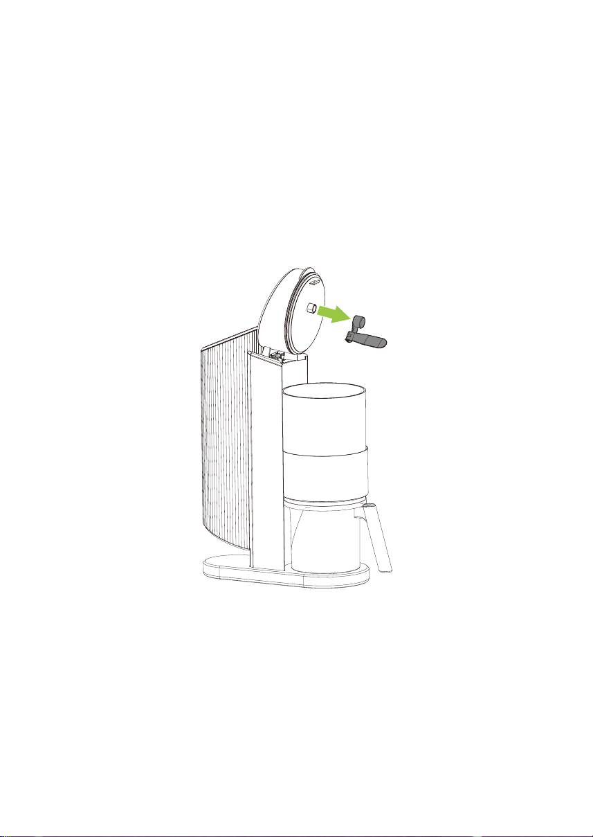
1. Ensure that the lower pot cover
motor is secured properly. See
“Securing the Lower Pot Cover
Motor” on page 35 for
instructions.
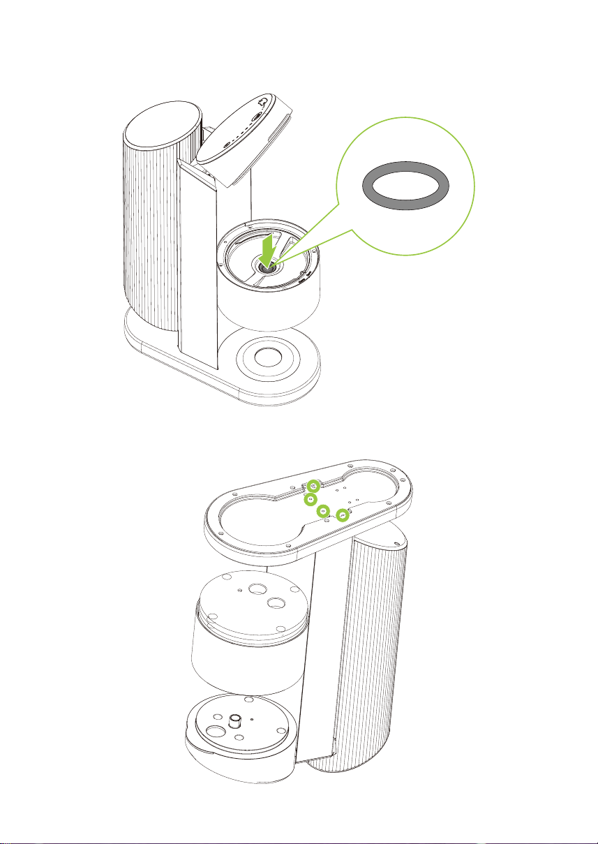
2. Replace the lower pot cover
motor. See “Replacing the
Lower Pot Cover Motor” on
page 31 for instructions.
3. Replace the mainboard. See
“Replacing the Mainboard” on
page 18 for instructions.
When the pump is
supposed to be
operating, it does
not fluctuate
between a hight
and low frequency
so it does not
sound like there is
any suction
occurring.
1. The lower pot has not
been properly pressure
sealed.
2. The lower pot cover
motor is faulty.
1. Correct the lower pot cover
pressure. See “Correcting the
Lower Pot Cover Pressure” on
page 33 for instructions.
2. Replace the lower pot cover
motor. See “Replacing the
Lower Pot Cover Motor” on
page 31 for instructions.
The stirrer is not
rotating.
1. Plastic rotary head is
faulty.
2. The stirrer motor is not
installed correctly.
3. The 6-pin stirrer motor
cable is faulty.
4. The mainboard is faulty.
1. Replace the plastic rotary head.
See “Replacing the Plastic
Rotary Head” on page 47 for
instructions.
2. Ensure that the stirrer motor is
secured properly. See “Securing
the Stirrer Motor” on page 46
for instructions.
3. Replace the 6-pin stirrer motor
cable. See “Replacing the 6-Pin
Stirrer Motor Cable” on
page 51 for instructions.
4. Replace the mainboard. See
“Replacing the Mainboard” on
page 18 for instructions.
Issue Possible Cause Suggested Solution