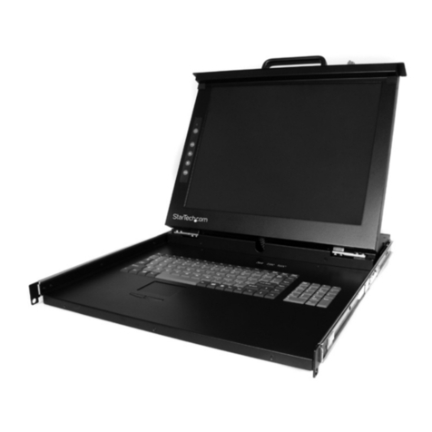
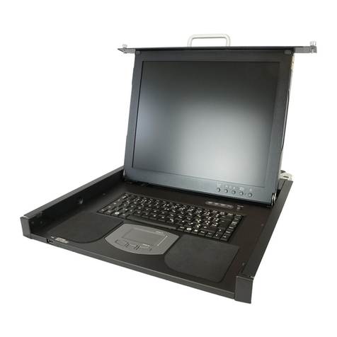
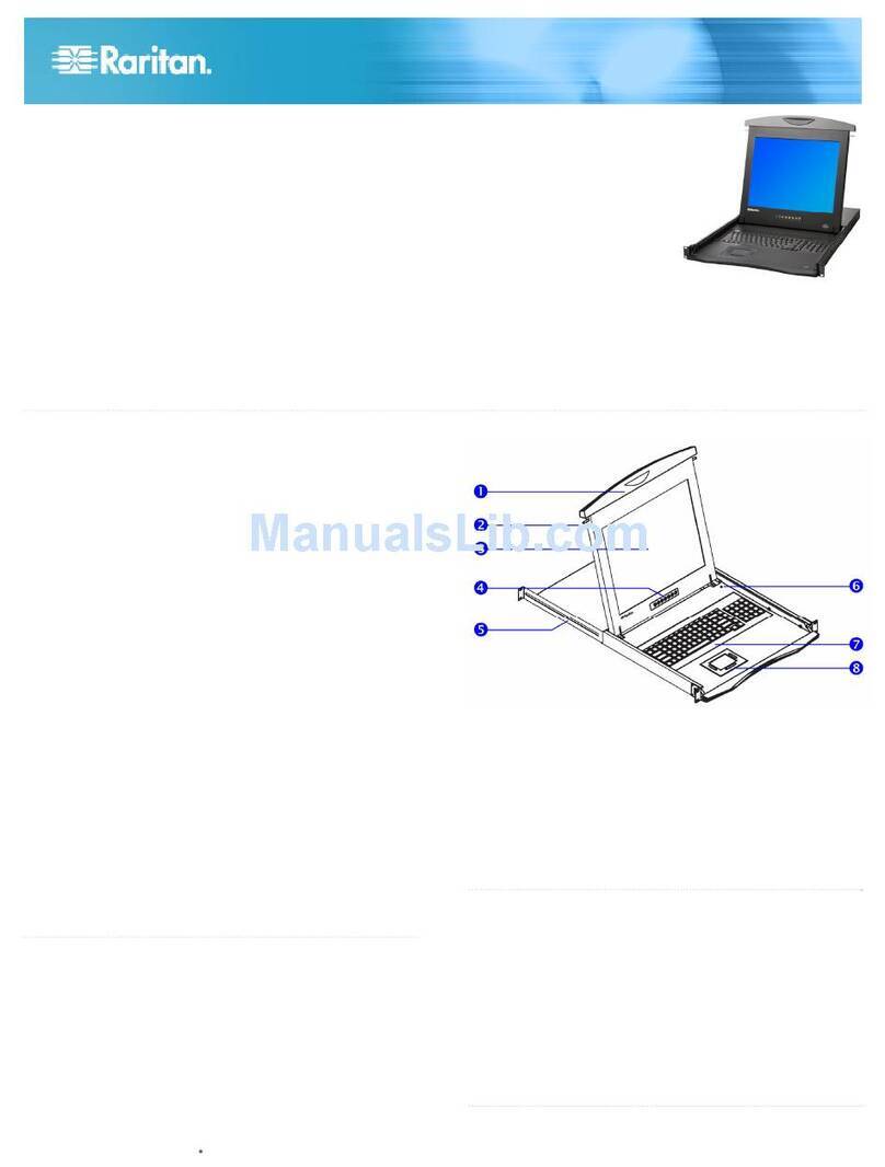
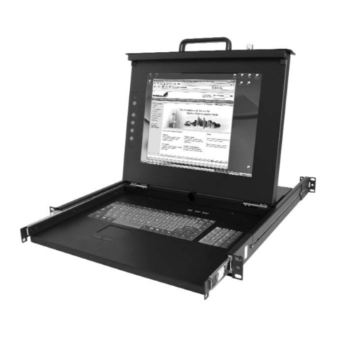
Raritan TZ1500 User manual

User Manual
TZ1500

This page intentionally left blank.

Raritan Computer Inc.
400 Cottontail Lane
S t NJ 08873
Raritan Computer Europe, B.V.
Eglantierbaan 16
2908 LV C ll d IJ l
Raritan Computer Japan, Inc.
Kuga Building 7F
11
6K 4
h
Raritan Computer Taiwan, Inc.
5F, 121, Lane 235,
P
Chi Rd H i Ti
Copyright ©2003 Raritan Computer, Inc.
KVM_TZ1500-0A-E
March 2003
255-37-0050
LISTE
D
CUS
L
U
1F61
I.T.E.
User Manual
TZ1500

This page intentionally left blank.

FCC Information
This equipment has been tested and found to comply with the limits for a Class A digital device,
pursuant to Part 15 of the FCC Rules. These limits are designed to provide reasonable protection
against harmful interference in a commercial installation. This equipment generates, uses, and can
radiate radio frequency energy and if not installed and used in accordance with the instructions, may
cause harmful interference to radio communications. Operation of this equipment in a residential
environment may cause harmful interference.
Trademark Information
Product names mentioned in this document are trademarks or registered trademarks of their
respective companies. KVM Drawer, Paragon, and their respective logos are trademarks or
registered trademarks of Raritan Computer, Inc. All other marks are the property of their respective
owners.
Japanese Approvals

This page intentionally left blank.

Table of Contents
CHAPTER 1: INTRODUCTION ............................................... 1
KVM Drawer TZ1500 Overview.......................................................................1
Product Photos ................................................................................................2
Product Features .............................................................................................3
Package Contents............................................................................................3
CHAPTER 2: KVM DRAWER AND Z-CIM INSTALLATION .......... 5
KVM Drawer Rack Mount Instructions.............................................................5
Z-CIM Connection............................................................................................7
Naming Attached Computers................................................................................8
Additional Z-CIM Connections.........................................................................9
Z-CIM Cabling Information ................................................................................. 11
Z-CIM On-Screen User Interface (OSUI) Functions......................................12
Help Menu.......................................................................................................... 13
Selection Menu................................................................................................... 13
Edit Menu ........................................................................................................... 14
System Profile Menu .......................................................................................... 14
System Profile Menu .......................................................................................... 15
LCD Panel......................................................................................................17
Factory Preset Timing for Reference.................................................................. 17
Power Indicator................................................................................................... 17
Other Rear Panel Ports .................................................................................18
Video Adjustment ............................................................................................... 18
Admin. ................................................................................................................ 18
CHAPTER 3: KVM DRAWER OPERATING INSTRUCTIONS........ 19
LCD Panel and OSD Controls............................................................................ 19
OSD Main Menu Functions ................................................................................ 21
Auto Tune........................................................................................................... 21
Brightness .......................................................................................................... 22
Contrast.............................................................................................................. 22
Color................................................................................................................... 23
Quality ................................................................................................................ 25
Position............................................................................................................... 27
Language ........................................................................................................... 30
Recall ................................................................................................................. 30
Exit ..................................................................................................................... 31
APPENDIX A: SPECIFICATIONS .......................................... 33
KVM Drawer TZ1500.....................................................................................33
Z-CIM Specifications......................................................................................33
LCD Panel......................................................................................................34
Model Differentiation......................................................................................34
APPENDIX B: TROUBLESHOOTING ...................................... 35
Z-CIM Troubleshooting..................................................................................36
APPENDIX C: FREQUENTLY ASKED QUESTIONS.................... 37
APPENDIX D: GLOSSARY .................................................. 41

Safety Instructions
1. Please read these safety instructions carefully.
2. Keep this User Manual for later reference.
3. Disconnect this equipment from the electrical outlet before cleaning. Do not use liquid or
spray detergent for cleaning. Use moisture sheet or cloth for cleaning.
4. For plug-in equipment, the outlet should be located near the equipment and should be
easily accessible.
5. Keep this equipment from humidity.
6. Rest this equipment on a reliable surface when installing. A drop or a fall could cause
injury.
7. Do not leave this equipment in an unconditioned environment where storage temperatures
rise above 40º C; it may damage the equipment.
8. The ventilation openings on the equipment are for air convection to keep it from
overheating. DO NOT COVER THE OPENINGS.
9. Make sure the voltage of the power source connecting to the equipment is appropriate.
10. Place the power cord in such a way that people cannot step on it. Do not place anything
over the power cord. The power cord must be rated for the voltage and current marked on
the product’s electrical ratings label. The voltage and current rating of the cord should be
greater than the voltage and the current rating marked on the product.
11. Please note all cautions and warnings on the equipment.
12. If the equipment is not in use for an extended time period, disconnect the equipment to
avoid being damaged by transient over-voltage.
13. Never pour any liquid into ventilation openings. This could cause fire or electrical shock.
14. If one of the following situations arises, get the equipment checked by service personnel.
− The power cord or plug is damaged.
− Liquid has gotten into the equipment.
− The equipment has been exposed to moisture.
− The equipment is not working well, or you cannot get it to work according to this User
Manual.
− The equipment has dropped and is damaged.
− The equipment has obvious signs of breakage.
15. Never open the equipment. Only qualified service personnel should open the equipment.

This page intentionally left blank.

CHAPTER 1: INTRODUCTION 1
Chapter 1: Introduction
KVM Drawer TZ1500 Overview
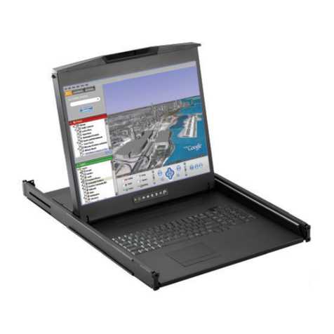
Raritan’s KVM Drawer Model TZ1500 is the first in the industry to offer the convenience of using
standard UTP cabling to connect servers up to 1,000 feet away. The KVM Drawer TZ1500 is a 1U
19” rack mount KVM console with built-in keyboard, touchpad, and LCD monitor. It offers highly
integrated Raritan Z-Series server management and enables control of up to 42 servers via industry
standard UTP cabling.
The KVM Drawer TZ1500 has a built in Z-Series KVM switch with Cat5 Simplicity and enables
quick and efficient access to servers and other network devices, as well as allowing you to manage
the setup, administration, and maintenance of rackmount servers in data centers, server rooms, and
other space-critical industrial environments.
Raritan’s innovative Z-CIM technology, built into the KVM Drawer TZ1500, enables access and
control of multiple servers from the single-user console of the KVM Drawer without consuming
valuable rack space. Through the TZ1500, you can control up to 42 servers and eliminate the
traditional KVM switch box and all extraneous cable. Z-CIM technology replaces the traditional
KVM switch-to-multiple-server cabling configuration with an innovative chain-like server-to-server
arrangement. Servers can be added at any time without interrupting server operation.

2 KVM DRAWER T1500 USER MANUAL
Product Photos
KVM Drawer TZ1500
UKVMSPD Z-CIM Unit

CHAPTER 1: INTRODUCTION 3
Product Features
• 1U 19” rack mount KVM drawer that meets EIA RS-310C standard
• 15” Active-Matrix LCD Flat Panel Display Color Monitor
• Tempered glass protecting the LCD panel
• Compact design enabling the unit to be mounted in most cabinets
• Industrial grade ultra-low-profile compact keyboard with integrated touchpad
• Zero-U design to support up to 42 computers
• Add a computer anywhere in the chain at any time
• Hot connect a user console to any server
• Hot-swap components with no impact on server operation
• Select computers by name from on-screen menus
• Supports high-resolution video—to 1600 x 1200
• Locate user up to 1,000 feet away with Category 5e UTP cable
• Administration (Admin.) Port for on-site firmware upgrades
Package Contents
The complete KVM Drawer TZ1500 package consists of:
• (1) 1U 19” Rack Mount KVM Drawer console
• (1) Mounting Kit (includes short and long brackets for customized fit)
• (1) TER-RJ45 Z-CIM Terminator
• (1) User Manual
• (1) Warranty Card
The complete KVM Drawer TZ1500 KIT package consists of:
• (1) 1U 19” Rack Mount KVM Drawer console
• (1) Mounting Kit (includes short and long brackets for customized fit)
• (3) Cat5e Cables
• (3) UKVMSPD Z-CIM units
• (1) TER-RJ45 Z-CIM Terminator
• (1) User Manual
• (1) Warranty Card
Check to make sure that the unit was not damaged in shipping. If you encounter a problem, contact
your reseller.
Please read this manual thoroughly and follow the installation and operation procedures carefully to
prevent any damage to the KVM Drawer, and/or any of the devices that connect to it.

4 KVM DRAWER T1500 USER MANUAL

CHAPTER 2: KVM DRAWER AND Z-CIM INSTALLATION 5
Chapter 2: KVM Drawer and Z-CIM Installation
Before you begin, make sure that power to all devices you will be connecting has been turned off. To
prevent damage to your KVM Drawer due to ground potential difference, make sure that all devices
on the installation are properly grounded. Please consult your vendor for any technical issues if
necessary or contact Raritan Technical Support at (732) 764-8886 or via email at
KVM Drawer Rack Mount Instructions
Before attaching pieces to your KVM Drawer, determine whether you will be using the short
brackets with the two-grid sliders or the longer brackets with the four-grid sliders. Select the pieces
according to the depth of the rack in which the unit will be mounted.
1. With the rear of the KVM Drawer facing you, use two screws to secure each small bracket
piece to the corners of the unit, as illustrated below.
2. Select the appropriate bracket arms and attach them to the sides of the KVM Drawer as
shown below. This bracket will fit over the small bracket piece attached in Step 1, and must
be secured with two screws from above and two screws from below.
Note: Notice that there are five openings (in the form of an “X”) at one end of
the bracket arm and there are two screws already in the KVM Drawer at two
points of the “X”; you can remove the two screws in the KVM drawer and
attach the bracket arm using five screws to fill all five holes.

6 KVM DRAWER T1500 USER MANUAL
3. With the rear of the KVM Drawer facing you, insert the slider into the bracket arm so that
the rack mount openings are aimed away from the unit. Attach the slider to the bracket arm
using the larger-head screws included in the kit.
Note: Leave the screws loose so that you can adjust the slider to the depth of
the rack when mounting the unit.
4. Secure the entire assembly to a rack using eight large rack screws (not included).
Remember to support the KVM Drawer until the assembly is securely fastened to the rack.

CHAPTER 2: KVM DRAWER AND Z-CIM INSTALLATION 7
Z-CIM Connection
Important! The KVM Drawer unit and the component being attached via Z-CIM must be
powered OFF prior to installation.
1. Connect the Category 5e UTP cable to the Cat5 port on the rear of the KVM Drawer
2. Connect the other end of Cat5e cable to UTP OUT port on a Z-CIM.
3. Place the Z-CIM terminator in the UTP IN port of the Z-CIM.
4. Connect the HD15 video port connector of the Z-CIM to the video port of the computer
being connected to the KVM Drawer, and then connect the 6-pin mini-DIN keyboard and
mouse connectors on the Z-CIM to the computer’s keyboard and mouse ports.
5. Plug the power cord into the KVM Drawer’s power jack, then plug the power cord into an
AC power source.
6. Power ON the KVM Drawer.
7. Name the newly connected computer (please refer to the section that follows, Naming
Attached Components, for further information).
Note: If you are connecting more than one computer/Z-CIM to your KVM
Drawer, please see the section that follows, Additional Z-CIM Connections,
for additional information.
2
Cat5 cable plugs into
“OUT”
p
ort on Z-CIM.
15
6
Rear view of KVM Drawer TZ1500

8 KVM DRAWER T1500 USER MANUAL
KVM Drawer attached to one Z-CIM and Computer
Naming Attached Computers
You must name the computer attached to the KVM Drawer via Z-CIM, and test for proper operation.
1. On the KVM Drawer keyboard, press the <Scroll Lock> key twice rapidly to view the
Z-CIM Selection Menu. A factory name and serial number for the Z-CIM will display on
the menu in your LCD Panel. The name represents the connected computer.
2. While the Selection Menu is displayed, press the <F3> key to open the Edit Menu.
3. The Edit Menu will appear and the name of the computer just added will be displayed in a
yellow highlight.
4. Press the <Enter> key; the highlight turns green
5. Type in a desired computer name and press the <Enter> key; the highlighted area will turn
yellow.
6. Press the <S> key to save the new name.
7. Press the <F2> key to return to the Selection Menu.
8. The Selection Menu will display the new computer name highlighted in white.
9. Press the <Enter> key to switch to the selected computer.
10. Normal computer access and operation indicates a successful connection.
Note: Function keys <F1>, <F2>, <F3>, and <F4> are used to switch among
menus. Pressing <F1> while OSUI is active invokes the Help Menu. This menu
lists all available menu options. Whenever the OSUI is invoked, the user
console keyboard’s <Scroll Lock> LED indicator blinks. Section 4. Operating
Z4200U gives more detail on OSUI menus and operations.
Last Z-CIM
K/B Video Mouse
UKVMSPD
Z-CIM Terminator
a
t
5
e
KVM Drawer
A
ttached Compute
r

CHAPTER 2: KVM DRAWER AND Z-CIM INSTALLATION 9
Additional Z-CIM Connections
Additional Z-CIMS can be added to the your KVM Drawer to allow control of up to 42 devices
from one central location. Repeat steps 1 through 3 below to add computers to the Z-Series chain.
Name and test each computer as it is added.
Note: Z-Series installation requires that each computer be assigned a channel
name as it is added to the Z-CIM chain. Computer channels are organized
alphabetically by assigned name (or the default name which is the Z-CIM’s
serial number), rather than in the order of their placement within the chain.
Connecting all computers first and then attempting to assign channel names
can cause difficulty when trying to locate the respective channel for each
computer.
1. Attach Z-CIM to computer to be added:
a. Connect the HD15 video port connector on the Z-CIM to the computer.
b. Connect the 6-pin mini-DIN keyboard and mouse connectors on the UKVMSPD
Z-CIM to computer’s keyboard and mouse ports.
2. Attach Z-CIM to chain:
a. Remove Z-CIM Terminator from the last Z-CIM’s UTP IN port and set aside.
b. Connect a Category 5e UTP cable to the UTP IN port on the Z-CIM that is currently
last in the chain.
c. Connect the other end of this Category 5e UTP cable to the UTP OUT port on the next
Z-CIM/computer currently being added to the chain.
d. Place the Z-CIM Terminator in the added Z-CIM’s UTP IN port.
e. Power ON computer.
f. Press the default hot key <Scroll Lock> twice rapidly at the KVM Drawer console to
bring up the OSUI.
g. Press <F2> to bring up the Selection Menu.
h. The new computer will appear as a new channel on the Selection Menu on the LCD
Panel of the KVM Drawer. A factory name and serial number for the Z-CIM will
display.
3. Name Computer and Test Operation:
i. At the Edit Menu on the LCD panel, the name of the computer just added will be
displayed in a yellow highlight.
j. Press the <Enter> key; the highlight turns green
k. Type in a desired computer name and press the <Enter> key; the highlighted area will
turn yellow.
l. Press the <S> key to save the new name.

10 KVM DRAWER T1500 USER MANUAL
m. Press the <F2> key to return to the Selection Menu.
n. The Selection Menu will display the new computer name highlighted in white.
o. Press the <Enter> key to switch to the selected computer.
p. Normal computer access and operation indicates a successful connection.
KVM Drawer attached to multiple Z-CIMs and Computers
Z-CIMs
Z-CIMs
Up to 42
C
a
t
5
e
C
C
ae
t
5
Servers
Up to 42
UKVMSPD
UKVM
SPD
UKVMSPD
UKVMSPD
C
ae
t
5
Z-CIM Terminator
Last Z-CIM in chain
Table of contents
Other Raritan LCD Drawer manuals