rastar BMW XR S1000 User manual


The BMW logo and the BMW wordmark are trademarks
of BMW AG and are used under License.
Http://www.rastar.com
08.06.877000.000260

Frequency bands: 2400MHz to 2483.5MHz
Maximum Transmitting Power (EIRP) : Not more than 10mW.

The product configuration functions include one-key startup, forward
gear, stop, backward gear, safety brake, left turn light and right turn
light, head light, rear brake light, sound and AUX socket. The
instructions are applicable for the following model products:
Solid color style
Electric vehicle, BMW
and motorcycle
Configured driving function
Supported foot brake
function

(102x31x57)cm
12.2kg
(0-4) km/hour (infinitely variable speed)
Input:AC100-240V 50Hz/60Hz Output:DC15V 1000mA
1
2
3
4
5
6
7
8
9
10
11
12
13
14
15
16
17
2 sets
1 set
1 set
1 Piece
1 volume
1 bottle
3 Pieces
2 sets
1 bar
Key
Vehicle body
Instructions
Lubricating oil
M5 screw
M6 screw and nut
AUX line
Balanced
wheel set
Left and
right pedals
12V 7Ah lead-acid
Rear license plate
Battery
Charger
M4 screw
Left handlebar set
1 Piece
1 Piece
1 Piece
6 Piece
1 Piece
1 Piece
1 set
1 set
Right handlebar
set
Left and right
rearview mirrors
Left and right
rearview mirrors


3-1 3-2
1
2
3
22
15 4
4
4
6
5
7
Left pedal
Right pedal
4-24-1
2.Installation of balanced wheel
set at the bottom
3.Installation of left and right
handlebar sets
The wire plug (as shown in the figure
3-1) at the end of handlebar
bibcock(as shown in the figure 4)
is taken in the body and is jointed
with female connector and male
connector of the handlebar (accessory
6). And then the wire and connectors
are taken back handlebar bibcock
tube and plugged back wire plug (as
shown in the figure 3-2). After that, the
handlebar is installed on the bibcock
and aligned with screw hole(as shown
in the figure 5). Finally, the screw is
put and the nut is equipped for locking
(as shown in the figure 3).
Left assembly: The left assembly
method is similar with that in the right.
Refer to the figure shown and conduct
installation (as shown in the figure 4).
The configured balanced wheel set at
the bottom(accessory 10)is aligned
with the screw hole(as shown in the
figure 2) / (as shown in the figure 3) of
body bottom(as shown in the figure
2)and the configured screws
(accessory 15 (M5x37.5 half-tooth
polar screw)) / (accessory
4(M4x12PB)) are taken for successive
locking(as shown in
the figure 2).
The equipped left and right pedals
(accessory 11) are installed and
tightly plugged along the card slot
(as shown in the Figure 1) to the
designated position (as shown in
Figure 2) of body pedal (as shown
in Figure 1)
Wire plug Wire plug
Wire plug
Wire plug
Nut
Nut
Right
handlebar set
Left
handlebar set
Screw
Screw
Male
connector
Male
connector
Female
connector
Female
connector
1.Installment of the left and right
pedals

9
10
1111
8
4. Installation of windscreen
5.Battery and power installation
6.Installation of rear license plate
cover
7.Installation of left and right
rearview mirrors
8.Assembly completion
Male
connector
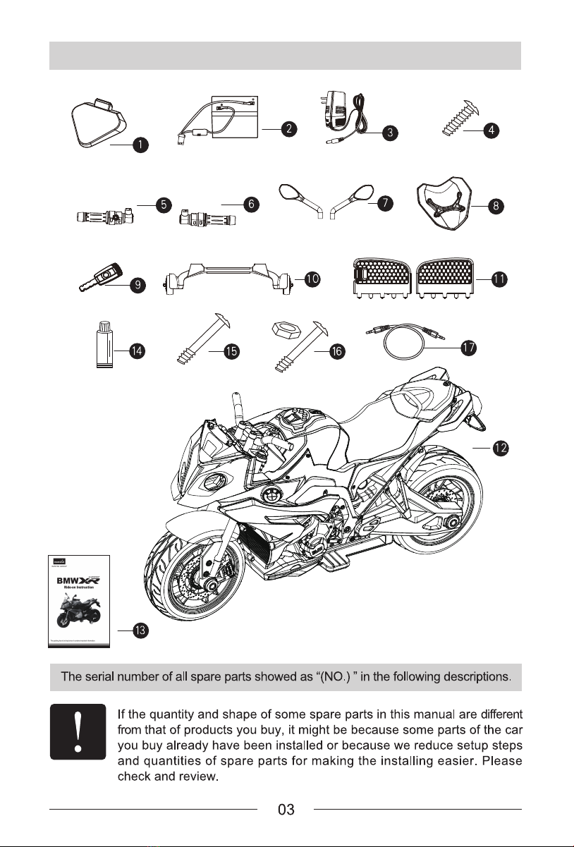
The configured windscreen
(accessory 8) is taken and the screw
hole (as shown in the figure 8) under
it is aligned with two screws of
vehicle head, and then configured
screw (accessory 4(M4x12PB)) is
applied for successive locking (as
shown in the figure 5).
The skewed slot behind the seat (as
shown in the figure 9) is set as left
and right turning. At that time, the
seat cover is taken to see the
configured battery (as shown in the
figure 6).
The configured connecting wire in the
battery slot is taken to connect two
pairs of male connector and female
connector (as shown in the figure 6).
The battery socket shall be noted that
the red wire corresponds with red wire
and the black wire corresponds with
black wire, without false connection,
otherwise, the short circuit may be
caused. After connecting the wire, the
seat can be installed back.
The designated button in the rear is
aligned (as shown in the figure 10) for
pressing. At the same time, the
configured rear license plate cover
(accessory 1) is taken and tightly
plugged upwards along the rear card
slot and then rear button is loosened
(as shown in the figure 10).
The left and right rearview mirrors
(accessory 7) are taken and the
rearview mirror handspike is aligned
with the designated position (as shown
in the figure 11) and tightly plugged
along the slot (as shown in the figure
8). (The installation method of left
rearview mirror is similar with that of
the right rearview mirror)
Notes: When the vehicle is
assembled or disassembled, note
installation order of accessories and
keep accessories in good condition.
Female
connector

9
3
10
BATTERY REPLACEMENT
NOTES
1.Notes to battery replacement
The seat cover is disassembled. The
male connector and female connector
are pulled out and then two-end wires
are untied in the positive and negative
electrodes of the battery. The screw
driver is applied to remove screw (M4X
12 screw) of the battery casting
component. After that, the battery
casting component (3) is taken and
then battery is taken for replacement
(as shown in the figure 9).
The battery with the same or equivalent type as or with the recommended
can be used.
The adult shall monitor the replacement of the battery.
The battery shall be placed according to the correct polarity and the short
circuit of the power supply terminal shall be avoided.
In case of long-term non-use, please take out the battery to avoid leakage
and corrosion; when the battery is lacking of electricity, it shall be taken
out of the car body.
The battery is equipped with self-
recovery fuse (over-current protector).
In case of any overload and improper
use, when the motor is closed, the
fuse will automatically disconnect
power for about 10 - 20 seconds, and
close key switch. After removing fault
and waiting for 10 seconds, the fuse
will make self-recovery.
Over-current
protector
The over-current protector is installed under the seat tail and can be seen
after the seat is taken when turning the skewed slot in the tail position.
Battery casting
component screw
Male
connector
Female
connector


OPERATION FUNCTION
12
Horn
AUX
Right
headlight
Power
switch
Safety switch
Lamplight
Steering
Volume up/
down
Brake
light
Left
turn light Right
turn light
Switch
lock sign
Forward /Stop/Back
Brake
One-key
startup
Charging
port
Throttle
Left
headlight

Vehicle startup: When the key is inserted
into key hole for twisting, the instrument
panel is on and then next key, namely
startup key, is pressed. At the same time,
all the functions in the whole vehicle are
started and the low-beam light is on.
Stop: The center console switch is
adjusted to stop gear for stopping
vehicle. In case of emergency brake in
the process of driving, the right pedal
can be directly depressed for starting
the brake function and the vehicle will
be stopped safely with the sound of
brake.
AUX: The instrument panel is equipped
with AUX for supporting external
equipment to play songs
Left turning: In the process of driving
forwards, the handlebar can be turned
towards left side, for realizing left turning.
Right turning: In the process of driving
forwards, the handlebar can be turned
towards right side, for realizing right
turning.
Turn light: Under the startup state, press
turn key, therein, the first-time pressing
indicates that the left turn light is on; the
second-time pressing indicates that the
right turn light is on; the third-time
pressing indicates that the emergency
flasher is on; the four-time pressing
indicates that the turn light effect is off.
Volume size: Slide volume size key, for
indicating that the volume size can be
adjusted.
Vehicle driving forwards: Under the startup
state, press forward gear function. Press
and hold handlebar switch with the left
hand and twist handlebar throttle (red
button) with the right hand at the same
time, for making the vehicle slowly drive
forwards.
Vehicle driving backwards: Under the
startup state,press backward gear function.
Press and hold handlebar switch with the
left hand and twist handlebar throttle (red
button) with the right hand at the same
time, for making the vehicle slowly drive
backwards.
Lighting: Under the startup state, press
lighting key, therein, the first-time pressing
indicates that the low-beam light is started;
the second-time pressing indicates that the
low-beam and high-beam light are started
simultaneously; the third-time pressing
indicates that the lighting effect is cancelled.
Horn: Under the startup state, press horn
key, for indicating that the horn sound will
ring immediately.
When the battery electricity consumption reaches to 80% of battery capacity, the
system will automatically start voice prompt of electricity shortage. After continuously
driving the vehicle for a period of time, the system will automatically turn off power.
The vehicle can be used after the full-charge battery. After the vehicle is placed for a
period of time, if the system still prompts electricity shortage, it means thebattery’
svoltage is at below level. Due to excessive low voltage of battery, the whole vehicle
will be not started. After the full-charge battery and the system fails to make prompts,
the vehicle can be started.
The cover plate under the seat back as shown in the
figure is set to replace mainboard accessories. In
case of any accessory replacement, unscrew screw
in the position referred by the arrow in the figure and
open cover plate and then see the mainboard. (as
shown in the figure 13)
The safety precautions describe how to use this
product happily and safely for children. Please
carefully read the following safety precautions.
For the battery charging, the adult must conduct operation rather than children.
The vehicle must be driven under the supervision, management and guidance of adult.
To avoid children to be frightened due to sudden driving forwards and backwards
after startup, the safety handlebar switch must be pressed and held with the left hand
when the vehicle is driven forwards and backwards and the throttle must be slowly
twisted
OPERATION FUNCTION
VEHICLE FUNCTION
WARNING
13

Cautions!
When the battery is replaced, the dangers of breakage, fever and liquid leakage
will occur. Therefore, please notice the following matters:
This toy car may be confronted with the falling of small parts during the use and
hence, it is not suitable for the children aged less than 36 months to use it.
The battery must be replaced by the adults.


A
-
+
Power indicator
Low-
beam
light
Power switch
Tail
light
High-
beam light
Left
turn
light Right turn light
Brake
light
Charging
panel
Charging
socket
Brake
switch
Over-current protector
Motor
Variable speed
Safety switch
Forward
Backward
One-key
startup
Left and
right turn
High-beam
and low-beam
light
Horn
Volume
switch
Horn
Remarks: This circuit diagram shall be only for reference. In case of any difference with the real object,
the real object shall prevail!
CIRCUIT DIAGRAM

Table of contents