Rath 2100-TDL User manual

N56W24720 N. Corporate Circle Sussex, WI 53089
866-850-8854 www.rathcommunications.com RP8500050
Ver. 7
10/18
Made in the USA
2 Year Warranty
Installation & Operations Manual
Emergency Tower Phone
• 2100-TDL Landline Dusk2Dawn Tower
• 2100-TDC Cellular Dusk2Dawn Tower
• 2100-TD9 900 MHz Dusk2Dawn Tower
• 2100-TDT 2-Way Radio Dusk2Dawn Tower
• 2100-TDV VoIP Dusk2Dawn Tower
• 2100-TDW Wi-Fi VoIP Dusk2Dawn Tower

N56W24720 N. Corporate Circle Sussex, WI 53089
866-850-8854 www.rathcommunication.com
Thank you for purchasing RATH’s Emergency Tower Phone. We are the largest Emergency Phone
Manufacturer in North America and have been in business for over 35 years.
We take great pride in our products, service, and support. Our Emergency Phones are of the highest
quality. Our experienced customer support teams are available to assist with site preparation, installation,
and maintenance. It is our sincere hope that your experience with us has and will continue to surpass
your expectations.
Thank you for your business,
RATH®Team
Table of Contents
Description . . . . . . . . . . . . . . . . . . . . . . . . . . .
Safety . . . . . . . . . . . . . . . . . . . . . . . . . . . . . . .
Site Preparation . . . . . . . . . . . . . . . . . . . . . . .
Items Needed . . . . . . . . . . . . . . . . . . . . . . . . .
Installation . . . . . . . . . . . . . . . . . . . . . . . . . . .
Communication . . . . . . . . . . . . . . . . . . . . . . .
Phone Programming . . . . . . . . . . . . . . . . . . .
Phone Testing . . . . . . . . . . . . . . . . . . . . . . . .
Phone Volume . . . . . . . . . . . . . . . . . . . . . . . .
Troubleshooting . . . . . . . . . . . . . . . . . . . . . .
Wiring . . . . . . . . . . . . . . . . . . . . . . . . . . . . . . .
Front
Page 3
Page 3
Page 3
Page 4
Page 4
Page 5
Page 6
Page 7
Page 7
Page 8
Page 9

Panel 1
Panel 2
Face Plate
Description
Safety Guidelines
• Save these instructions. This manual contains important instructions that will assist you during
installation and maintenance.
• Keep all the components secure and protected during storage.
• Be careful of nished surfaces during transport and installation to avoid damaging the nish.
• Installation and maintenance should only be performed by qualied electricians.
• It is recommended a minimum of 2 people perform installation.
• Do not install phone during extreme weather conditions.
• Do not touch uninsulated phone wires or terminals unless the phone line has been disconnected at
the network interface.
• Do not invert the battery.
Page 3
Back
Figure 1: Front & Back View
Front
Face Plate
• ADA compliant (hands free operation)
• LED call status indicator
• Powder coated steel construction inside and out
• Aluminum access panels powder coated inside and out
• Weather and vandal resistant
• Blue beacon and strobe with photocell
• Strobe turns on upon phone activation
• Recessed illuminated face plate
• Internal anchor base plate
• 4 hour phone battery backup*
• Ability to program up to 5 emergency numbers*
• Remote or on-site programmable**
• Panels secured with security screws
• Torx bit provided to access panels
Features:
Height 9’
Width 10-3/4”
Depth 6”
Thickness of Steel 11 Gauge
Weight 167 lbs.
Tower Specications:
*Not applicable for 2-Way Radio application
**Not applicable for 2-Way Radio, Cellular, or 900 MHz application
Tower Site Preparation Instructions
1. Concrete mounting pad should be at least 16” in depth and 2’ in diameter
2. Insert the 3/4” x 12” galvanized rods per mounting template provided
3. A minimum 2” of thread must be exposed above level of concrete
4. Let concrete set for a minimum of 48 hours to cure

Items Needed for Installation
Tower Installation
Page 4
• Concrete for 16” deep, 2’ diameter slab
• Rath Kit 7476* or 7477**
• #1 Phillips screwdriver
• 1/4” driver
• Torx bit (provided to remove Access Panels)
*7476 (For New Concrete)
• (4) 3/4” x 12” galvanized anchor bolts
• (12) 3/4” at washers
• (4) 3/4” hex nuts
• (4) 3/4” SAE washers
• (4) split lock washers
**7477 (For Existing Concrete)
• (4) anchors
• (4) 3/4” x 4” galvanized anchor bolts
• (1) setting tool
• (8) 3/4” at washers
• (4) split lock washers
• 1/4” spanner adapter (provided to remove
Access Panel 1)
• Adjustable wrench
• Analog phone line (if using 900 MHz or a Landline)
• Phone cable (if using 900 MHz or a Landline)
1. Lay tower on its side with the base next to the concrete pad.
2. Open Access Panel 2 on back of tower (see Figure 1).
3. Feed the electrical and phone wires in the conduit into the tower base through the 4” hole.
4. Align the tower mounting holes with the four 3/4” galvanized rods and lift on to the concrete slab.
5. Put a lock washer on each rod along with a nut and secure tightly.
Connecting the Electric Lines:
1. Locate the blue (positive), brown (negative), and green (ground) wires coming out of the bottom of the
tower from the charging station.
2. Connect the electrical wires from the 120v power supply, run through conduit, to the wires in the tower
using the waterproof wire nuts located on the wires.
Connecting the Phone and Turning On the Electric Power:
1. Locate the gray phone cable coming out of the NEMA 4 box behind the face plate.
2. If using an analog phone line for communication, connect tip and ring from phone line run through
conduit to red and green phone cable coming out of the NEMA 4 box.
Note: If using Cellular or 900 MHz, phone line should already be connected within tower.
3. Turn on the electrical power.
Note: If using 480v or 277v, an additional transformer will be installed in the tower. The wire connections should be
made at this time according to the manufacturer’s instructions.
Warning! Electrical Connection Should Be Performed by a Qualied Electrician!

Communication
Page 5
To connect your analog phone line to the tower:
1. Remove the face plate (see Figure 1).
2. Locate the gray phone cable coming out of the NEMA 4 box.
3. Connect the gray phone cable to the phone cable that was run through the conduit either by connecting
the modular jack or the Red and Green wires.
Landline:
GSM Cellular:
CDMA Cellular:
2-Way Radio:
900 MHz:
1. Open Access Panel 1 (see Figure 1) using torx bit to remove security screws.
2. Remove the cover of the NEMA 4 enclosure.
3. Locate the Cellular Module inside the enclosure.
4. When the “PWR”, “RDY”, and “NW” lights on the front of the unit are illuminated, unit is ready.
5. Verify SmartPhone is plugged into the FXS port on Cellular Module.
Note: If the Sim card is not provided to Rath at time of purchase, an active Sim Card will need to be installed into Sim Card slot.
1. Open Access Panel 1 (see Figure 1) using torx bit to remove security screws.
2. Remove the cover of the NEMA 4 enclosure.
3. Locate the Cellular Module inside the enclosure.
4. When “Power”, “Signal Strength”, and “Service Indicator” lights are illuminated solid, unit is ready.
5. Verify SmartPhone is plugged into the phone port on Cellular Module.
The 2-Way Radio phone can both transmit and receive voice communications. Our 2-Way Radios
are xed in the tower and must be programmed to the specics of the 2-Way System in use within the
facility or campus. The 2-Way Radio is programmed at the factory using customer provided information
(frequency, squelch code, and narrow or wide bandwidth). The antenna is installed and tuned at the
factory. Towers using 2-Way Radio are not ADA compliant (the button must be pushed and held to talk
and let go to listen).
Phones using 2-Way Radios are not programmable. Sections in this manual on Programming the Phone do not apply.
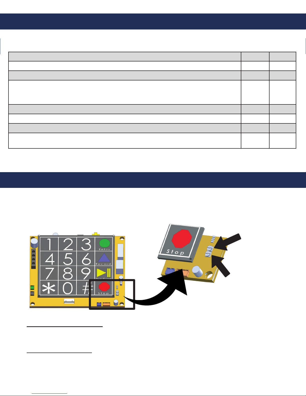
Adjusting the Volume for 2-Way Radio:
1. If the volume of the tower needs to be adjusted, remove the face plate.
2. Open the NEMA 4 box to access the radio. Turn the radio volume control up or down to adjust.
3. Close the NEMA 4 box and reattach the face plate.
Note: If installing multiple 900 MHz units, please put a minimum of 3 feet between each Base Station. Connect
one unit at a time, test, and then continue adding one unit and testing until all units are ready and functional.
1. Locate the 900 MHz unit with Base Station labeled on the bottom.
2. Screw black antenna into back of 900 MHz Base Station.
3. Plug dedicated analog phone line or analog extension o of a PBX system into the port labeled “Line”.
4. Connect Power Cable included with unit into dc input on Base Station and a 120v outlet.
5. Test units by taking an analog phone and plugging it into the “Line” Port on Remote Station installed in
the tower. There should be a dial tone and you should be able to place a call out.
6. Verify SmartPhone is plugged into “Tel” Port on Remote Station. Phone is now ready for programming.
Each tower includes (2) 900 MHz units, (1) Remote Station, and (1) Base Station. The Remote
Station is already installed in the tower.
• 1/4” spanner adapter (provided to remove
Access Panel 1)
• Adjustable wrench
• Analog phone line (if using 900 MHz or a Landline)
• Phone cable (if using 900 MHz or a Landline)

Programming the Phone
On-Site Programming:
Remote Programming:
Step 1. To Begin Program Mode
A. Press Enter
Step 2. To Program Emergency Numbers
A. Press 1, Enter, (phone number), Stop
Note: Press 2-5 in step 2A for emergency numbers 2-5 as needed
Step 3. To Program Location Message
A. To turn on message Press 1, 3, Enter, 2
B. Press 6, Record (speak message) Stop (to replay message Press 6, Play)
C. For no message Press 1, 3, Enter, 0
Step 4. To Program Auto Disconnect Time (Default is 5 minutes, lowest interval is 1 minute)
A. Press 8, Enter, (3 digit number in minutes)
Ex: 2 minutes = 002
Step 5. To Exit Program Mode
A. Press Stop for 3 seconds
Step 1. To Begin Program Mode
A. Call into phone by dialing the number of the phone
B. After rst simulated ring, Press #, # (Wait for 4 tones)
C. Key in security code (Default is 1111) (Wait for conrmation tones)
Step 2. To Program Emergency Numbers
A. Press 1, *, (Phone number), *, # (Wait for conrmation tones)
Note: Emergency numbers (2-5) repeat step 2A pressing (2-5) as needed
Step 3. To Program Location Message
A. To turn on message press 1, 3, *, 2 (Wait for conrmation tones)
B. Press 6, *, (Speak message) #, *, # (Wait for conrmation tones)
i. To replay message Press 6, # (Wait for conrmation tones)
C. For NO message Press 1, 3, *, 0 (Wait for conrmation tones)
Step 4. To Program Auto Disconnect Time (Default is 5 minutes, lowest interval is 1 minute)
A. Press 8, *, (3 digit number in minutes)
Ex: 2 minutes = 002
Step 5. To Exit Program Mode
A. Press *, #, 0 (You will hear a beep, beep) *, # (You will hear a buzz)
Keypad
Page 6
1. You can program the phone on-site or remotely.
Note: Cellular and 900 MHz applications cannot be remotely programmed.
2. If programming on-site, remove the face plate. Use the #10 spanner bit provided to remove the
6 security screws.
3. Remove the cover of the NEMA 4 enclosure by loosening the 4 corner screws.
VoIP & Wi-Fi VoIP:
See additional manual.

Testing the Phone
Did you hear a dial tone?
Did the strobe start ashing immediately after the button was pushed?
Did the red LED become a solid light when you pushed the button?
Did the red LED ash and approximately 15-20 seconds later the called party
started talking to you? (Delay is due to the phone telling the other party your
location via the “Location Message”)
Can you hear the other party clearly? (If not, see “Adjust Speaker” below)
Can the other party hear you clearly? (If not, see “Adjust Microphone” below)
When the party you called hangs up, does the strobe stop?
If you have answered YES to all questions, you have successfully installed and tested
the phone. If you answer NO to any question, proceed to the Troubleshooting Section.
Push the silver emergency button on the front of the tower:
Yes No
* Rath recommends the tower phone be tested on a regular basis to ensure proper operation.
Adjusting the Volume
Volume Adjust VR1
Mic Sensitivity VR2
Adjusting the Microphone:
If the person you are calling reports your voice is not loud enough, increase the Microphone
Sensitivity by adjusting VR2 a 1/4 turn clockwise (requires a small Phillips screwdriver).
Adjusting the Speaker:
If the voice of the person you call is not loud enough in the phone speaker, increase the volume
by adjusting VR1 a 1/4 turn clockwise.
Page 7
Rath SmartPhone
If the volume is too low or high, adjust it by referring to the diagram and instructions below.
Note: Refer to the instructions under “Programming the Phone” to access the circuit board.

Troubleshooting
Problem Possible Cause & Solutions
No dial tone when the
button is pushed:
• Check to make sure the phone line is connected to
SmartPhone board.
• Verify dial tone and voltage on phone line going into unit.
Audio is low from the
speaker:
• Speaker control needs to be adjusted. Go to “Speaker
Adjustment” on page 6.
• Make sure the speaker holes are not blocked.
Audio is distorted from the
speaker:
• Speaker control needs to be adjusted. Go to “Speaker
Adjustment” on page 6.
• Make sure there are no items touching the speaker inside the tower.
When the called party
hangs up, strobe
continues to ash:
• Phone company or phone system is not providing a disconnect
signal. Contact the appropriate party to make sure the
disconnect signal is provided.
When the called party
hangs up, busy signal is
heard through speaker:
• Phone company or phone system is not providing a disconnect
signal.
• Operator needs to press *, # to disconnect the call.
• Disconnect time on phone needs to be lowered (see page 5).
Tower appears non-
functional. Strobe does
not ash and no audio is
heard from the speaker
when button is pushed:
• Check to make sure the phone line is connected from the
communication source.
• Check electrical connections and 120v supply to transformer.
• Push button may be non-functional.
LED above push button
comes on and goes o
immediately:
• No dial tone or operating voltage from communication source.
• Remove line from SmartPhone and connect to analog phone.
Verify 2-way calling.
Page 8

Page 9
Wiring
Wiring Diagram
pg. 8
Strobe
Wago Connector to front plate
1
45
7 8
0
9
6
3
2
Enter
Record
Play / Pause
Stop
*
#
Constant
Strobe
120v
Phone line
to cellular unit
Charging/Finishing/Ready
Dusk2Dawn Charging Station
Ground
Positive Negative
Photocell
yrettaB
BATTERY
Transformer
(Only if using 277
or 480v power)
Reference the manufacturer’s
instructions for the wire connections
This manual suits for next models
5
Table of contents
Other Rath Telephone manuals