Troubleshooting
Problem Possible Cause & Solutions
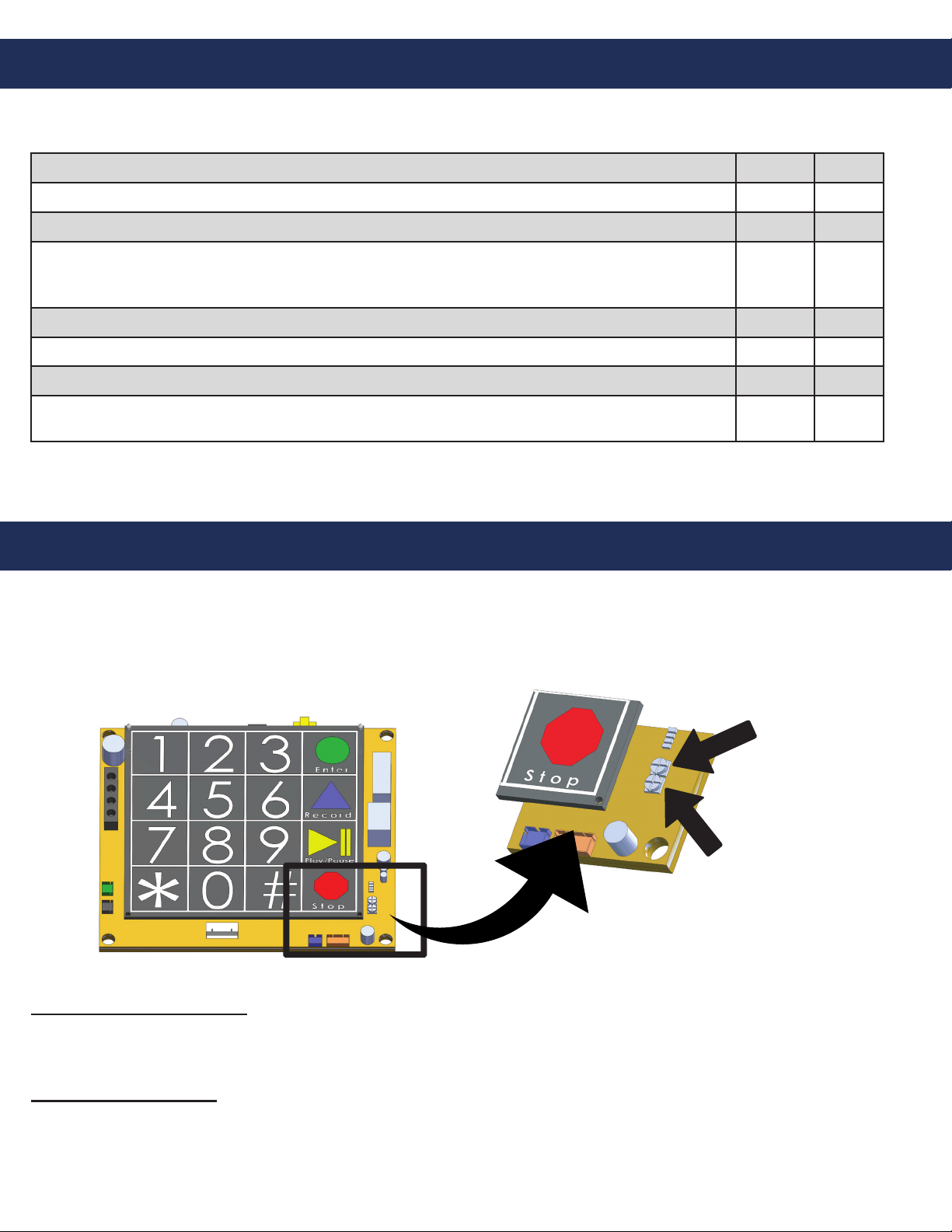
No dial tone when the
button is pushed:
• Check to make sure the phone line is connected to SmartPhone board.
Audio is low from the
speaker:
• Speaker control needs to be adjusted. Go to “Speaker Adjustment” on page 9.
• Make sure the speaker holes are not blocked.
Audio is distorted from the
speaker:
• Speaker control needs to be adjusted. Go to “Speaker Adjustment” on page 9.
• Make sure there are no items touching the speaker inside the Tower.
When the called party hangs
up, strobe continues to ash:
• Phone company or phone system is not providing a disconnect signal. Contact
the appropriate party to make sure the disconnect signal is provided.
• Press * , # to simulate disconnect signal.
When the called party hangs
up, strobe continues to ash for
one minute:
• Slow disconnecting signal from the communication source. This is
considered normal operation.
When the called party hangs
up, busy signal is heard
through speaker:
• Phone company or phone system is not providing a disconnect signal.
• Operator needs to press *, # to disconnect the call.
• Disconnect time on phone needs to be lowered (see page 8).
Tower appears non-functional.
Strobe does not ash and no
audio is heard from the
speaker when button is
pushed:
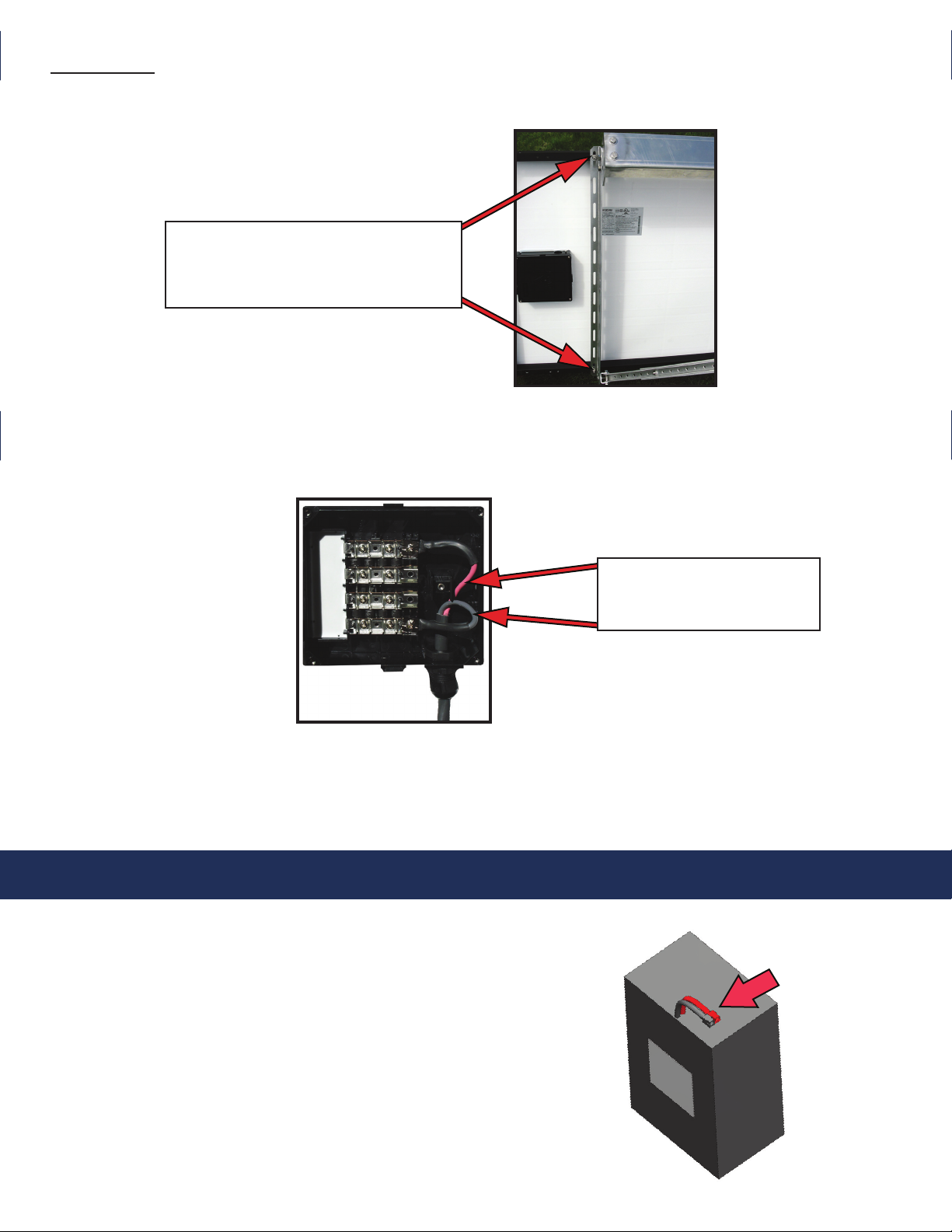
• Access the waterproof enclosure containing the Sun Saver Regulator located
behind the face plate (see Figure 1).
• Disconnect the two wires connected to the “solar” terminals. Using a voltmeter,
measure the voltage across the two terminals. It should read approximately 20
volts dc on a sunny day. If voltage is low or 0, the panel may be damaged.
• Disconnect the two wires connected to the “battery” terminals on the
Sun Saver Regulator. Using a voltmeter, measure the voltage across the two
terminals. It should be 12.8 volts dc. If voltage is low, battery may not be getting
charged or holding a charge. If voltage is 0, check to make sure the battery is
connected properly.
• Verify 12 volts are going to the SmartPhone board.
Tower works in the afternoon
but not at night or early in the
morning:
• Be sure the solar panel is not shaded by trees or other objects.
• Access the waterproof enclosure containing the Sun Saver Regulator located
behind the face plate (see Figure 1).
• Disconnect the two wires connected to the “solar” terminals. Using a voltmeter,
measure the voltage across the two terminals. It should read approximately 20
volts dc on a sunny day. If voltage is low or 0, the panel may be damaged.
• Disconnect the two wires connected to the “battery” terminals on the Sun Saver
Regulator. Using a voltmeter, measure the voltage across the two terminals. It
should be 12.8 volts dc. If voltage is low, battery may not be getting charged or
holding a charge. If voltage is 0, check to make sure the battery is connected
properly.
Blue light stays on
constantly, even though it
should only be on at night.
• Check photocell adjustment on page 6.
• Cover the opening of the photo eye. The blue light should go out. If the
light stays lit, photodiode may be damaged.
Page 10