Ebyte E32-400T20S User manual

E32-400T20S User Manual
SX1278 430MHz 100mW SMD Wireless Module

Chengdu Ebyte Electronic Technology Co,;Ltd E32-400T20S User Manual
Copyright ©2012–2019,Chengdu Ebyte Electronic Technology Co,;Ltd 1
CONTENTS
1. OVERVIEW..................................................................................................................................... 3
1.1 INTRODUCTION.............................................................................................................................................................. 3
1.2 FEATURES.......................................................................................................................................................................3
2.SPECIFICATION AND PARAMETER......................................................................................................................................4
2.1 LIMIT PARAMETER......................................................................................................................................................... 4
2.2 OPERATING PARAMETER................................................................................................................................................ 4
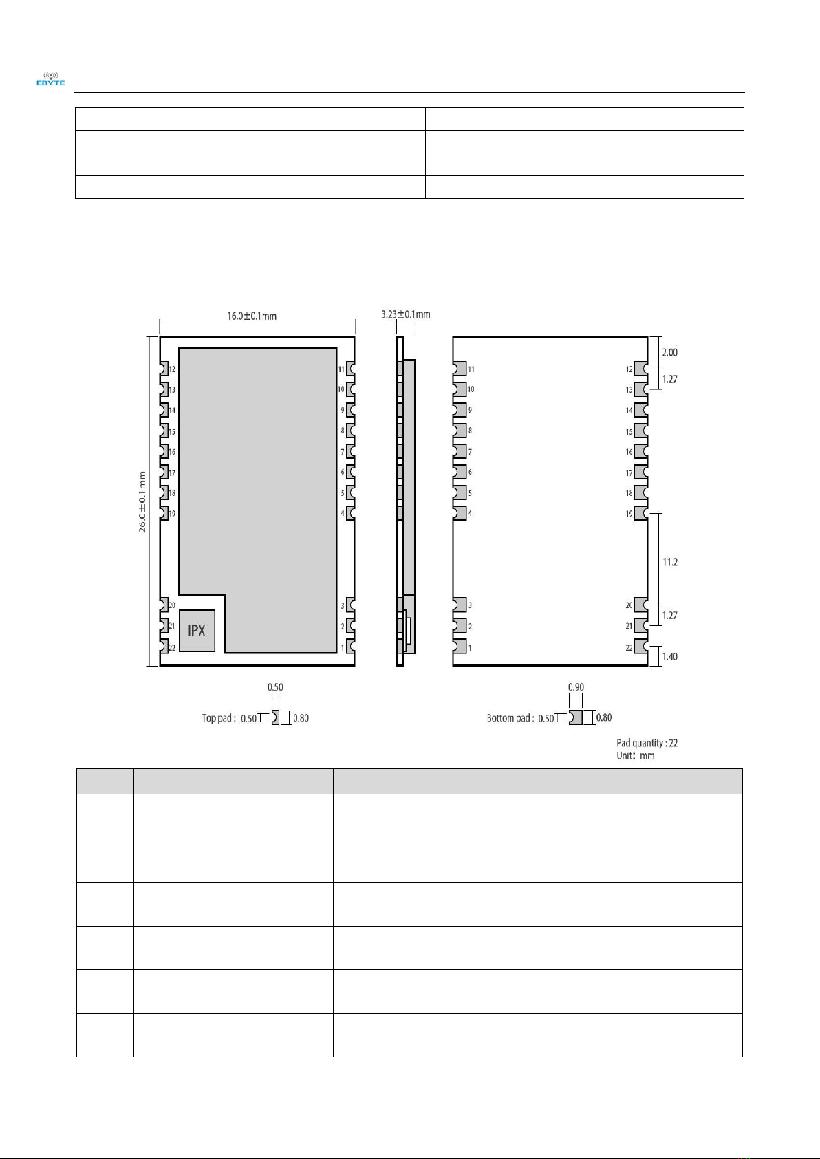
3 SIZE AND PIN DEFINITION......................................................................................................... 5
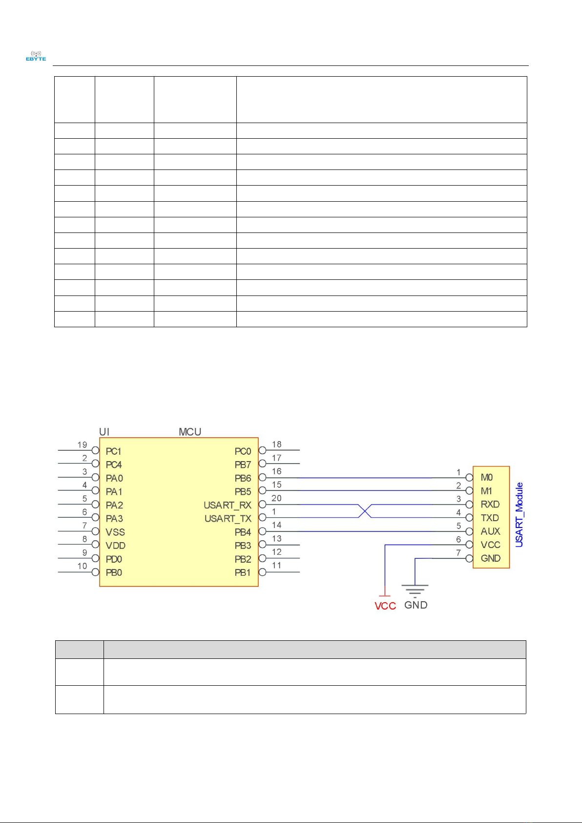
4. CONNECT TO MCU.......................................................................................................................6
5 FUNCTION DESCRIPTION...........................................................................................................7
5.1 FIXED TRANSMISSION....................................................................................................................................................7
5.2 BROADCASTING TRANSMISSION.................................................................................................................................... 7
5.3 BROADCASTING ADDRESS............................................................................................................................................. 7
5.4 MONITOR ADDRESS....................................................................................................................................................... 8
5.5 RESET............................................................................................................................................................................ 8
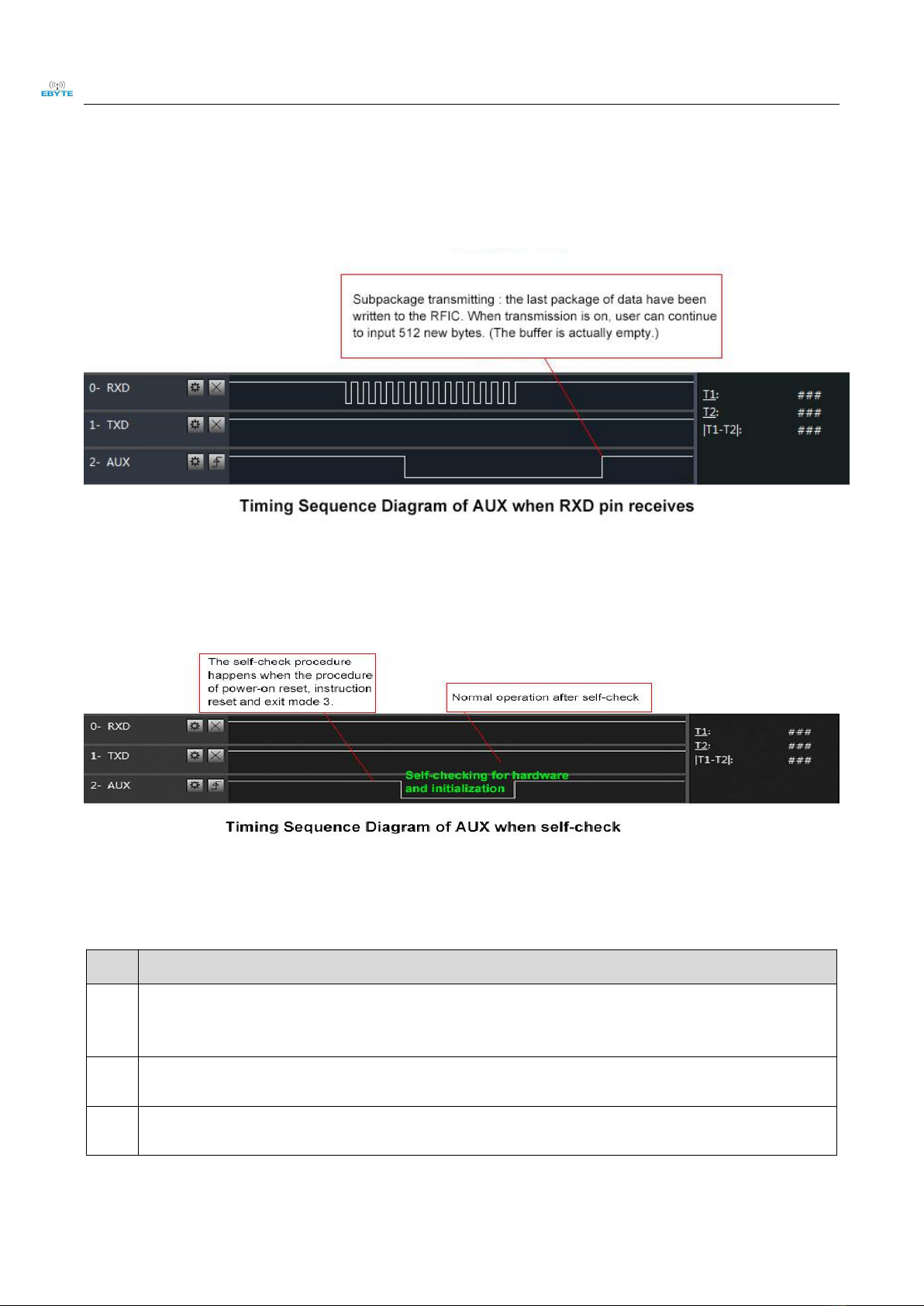
5.6 AUX DESCRIPTION........................................................................................................................................................ 8
5.6.1 Indication of UART output.....................................................................................................................................8
5.6.2 Indication of wireless transmitting........................................................................................................................ 8
5.6.3 Configuration procedure of module.......................................................................................................................9
5.6.4 Notes for AUX........................................................................................................................................................ 9
6 OPERATING MODE..................................................................................................................... 10
6.1 MODE SWITCH............................................................................................................................................................. 10
6.2 NORMAL MODE (MODE 0)............................................................................................................................................11
6.3 WAKE-UP MODE (MODE 1)...........................................................................................................................................11
6.4 POWER-SAVING MODE (MODE 2)..................................................................................................................................11
6.5 SLEEP MODE (MODE 3)................................................................................................................................................ 12
7 COMMAND FORMAT.................................................................................................................. 12
7.1 DEFAULT PARAMETERS................................................................................................................................................ 12
7.2 READING OPERATING PARAMETERS............................................................................................................................. 13
7.3 READING VERSION NUMBER........................................................................................................................................13
7.4 RESET COMMAND........................................................................................................................................................ 13
7.5 PARAMETER SETTING COMMAND.................................................................................................................................13
8. HARDWARE DESIGN................................................................................................................. 15
9 FAQ...................................................................................................................................................16
9.1 COMMUNICATION RANGE IS TOO SHORT......................................................................................................................16
9.2 MODULE IS EASY TO DAMAGE.....................................................................................................................................16
9.3 BER(BIT ERROR RATE)IS HIGH................................................................................................................................17
10 PRODUCTION GUIDANCE...............................................................................................................................................17
10.1 REFLOW SOLDERING TEMPERATURE......................................................................................................................... 17

Chengdu Ebyte Electronic Technology Co,;Ltd E32-400T20S User Manual
Copyright ©2012–2019,Chengdu Ebyte Electronic Technology Co,;Ltd 2
10.2 REFLOW SOLDERING CURVE...................................................................................................................................... 18
11 E32 SERIES................................................................................................................................... 18
12 ANTENNA RECOMMENDATION.........................................................................................19
13 PACKAGE FOR BATCH ORDER............................................................................................. 20
REVISION HISTORY.......................................................................................................................21
ABOUT US..........................................................................................................................................21

Chengdu Ebyte Electronic Technology Co,;Ltd E32-400T20S User Manual
Copyright ©2012–2019,Chengdu Ebyte Electronic Technology Co,;Ltd 3
1.Overview
1.1 Introduction
E32-400T20S UART wireless modules based on
SX1278 of SEMTECH with transparent transmission
and LoRa spread spectrum technology. SX1278 support
LoRa technology, The LoRa DSSS (direct sequence
spread spectrum) technology features long range and
strong anti-interference as well as strong data
confidentiality. SX1278 are considered as a milestone in
terms of low speed data communication,(default
470MHz) with max 197 bytes per package.SX1278
features LoRa™ technology, LoRa will bring longer
communication distance, and has the advantages of
concentrated power density, meanwhile it has a very strong confidentiality.
The modules of 20dBm transmitting power adopt industrial grade crystal oscillators to ensure the stability and
consistency, its precision is lower than the widely adopted 10ppm. E32 series are in stable bulk production and are widely
applied in utility meters, IoT renovation, smart home, etc. The modules feature data encryption and compression. The
data transmitted in air features randomness. The encryption-decryption algorithm makes data interception meaningless.
And the data compression enables shorter transmitting time and lower rate of being interfered, which increased the
reliability and transmitting efficiency.
1.2 Features
Communication distance tested is up to 3km
Maximum transmission power of 100mW, software multi-level adjustable;
Support the global license-free ISM 470MHz band;
Support air date rate of 0.3kbps~19.2kbps;
Low power consumption for battery supplied applications;
Support 3.3V~5.2V power supply, power supply over 5.0V can guarantee the best performance;
Industrial grade standard design, support -40 ~ 85 °C for working over a long time;
IPEX and stamp hole optional, good for secondary development and integration.
1.3 Application
Home security alarm and remote keyless entry;
Smart home and industrial sensors;
Wireless alarm security system;
Building automation solutions;
Wireless industrial-grade remote control;

Chengdu Ebyte Electronic Technology Co,;Ltd E32-400T20S User Manual
Copyright ©2012–2019,Chengdu Ebyte Electronic Technology Co,;Ltd 4
Health care products;
Advanced Meter Reading Architecture(AMI);
Automotive industry applications.
2. Specification and parameter
2.1 Limit parameter
Main parameter
Performance
Remark
Min.
Max.
Power supply(V)
0
5.2
Voltage over 5.2V will cause
permanent damage to module
Blocking power(dBm)
-
-10
Chances of burn is slim when
modules are used in short distance
Operating temperature(℃)
-40
85
-
2.2 Operating parameter
Main parameter
Performance
Remark
Min
Typ.
Max.
Operating voltage(V)
3.3
5.0
5.2
≥5.0 V ensures output power
Communication level(V)
-
3.3
-
For 5V TTL, it may be at risk of
burning down
Operating temperature(℃)
-40
-
85
Industrial design
Operating frequency(MHz)
410
-
525
Support ISM band
Power
consump
tion
Transmitting current
[mA]
-
106
Instant power
consumption
Instant power consumption
Receiving current [mA]
-
15
-
-
Turn-off current [μA]
-
4
-
Software is shut down
Max Tx power(dBm)
19.0
-
20.0
-
Receiving sensitivity(dBm)
-144
-146
-147
Air data rate is 2.4kbps
Air data rate(bps)
0.3k
2.4k
19.2k
Controlled via user’s programming
Main parameter
Description
Remark
Distance for reference
3000m
Test condition:clear and open area, antenna gain: 5dBi,
antenna height: 2.5m,air data rate: 2.4kbps
TX length
197 Byte
Maximum capacity of single package
Buffer
512 Byte
-
Modulation
LoRa™
-
Communication interface
TTL
@3.3V

Chengdu Ebyte Electronic Technology Co,;Ltd E32-400T20S User Manual
Copyright ©2012–2019,Chengdu Ebyte Electronic Technology Co,;Ltd 5
Package
SMD
-
Connector
1.27mm
-
Size
16 * 26mm
-
Antenna
IPEX/stamp hole
50 ohm impedance
3 Size and pin definition
No.
Name
Direction
Function
1
GND
-
Ground
2
GND
-
Ground
3
GND
-
Ground
4
GND
-
Ground
5
M0
Input
(weak pull-up)
Work with M1 to decide 4 working modes of module (not suspended,
if not used, could be grounded).
6
M1
Input
(weak pull-up)
Work with M0 to decide 4 working modes of module (not suspended,
if not used, could be grounded).
7
RXD
Input
TTL UART inputs, connects to external (MCU, PC) TXD output pin. Can be
configured as open-drain or pull-up input.
8
TXD
Input
TTL UART outputs, connects to external RXD (MCU, PC) input pin. Can
be configured as open-drain or push-pull output

Chengdu Ebyte Electronic Technology Co,;Ltd E32-400T20S User Manual
Copyright ©2012–2019,Chengdu Ebyte Electronic Technology Co,;Ltd 6
9
AUX
Input
To indicate module ’ s working status & wakes up the external MCU.
During the procedure of self-check initialization, the pin outputs low
level. Can be configured as push-pull output (suspending is allowed).
10
VCC
-
Power supply :2.3~ 5.2V DC
11
GND
-
Ground
12
NC
-
-
13
GND
-
Ground
14
NC
-
-
15
NC
-
-
16
NC
-
-
17
NC
-
-
18
NC
-
-
19
GND
-
Ground
20
GND
-
Ground
21
ANT
-
Antenna
22
GND
-
Ground
4. Connect to MCU
No.
Description(STM8L MCU)
1
The UART module is TTL level.
2
For some MCU works at 5VDC, it may need to add 4-10K pull-up resistor for the TXD & AUX pin.

Chengdu Ebyte Electronic Technology Co,;Ltd E32-400T20S User Manual
Copyright ©2012–2019,Chengdu Ebyte Electronic Technology Co,;Ltd 7
5 Function description
5.1 Fixed transmission
5.2 Broadcasting transmission
5.3 Broadcasting address
For example: Set the address of module A as 0xFFFF , and the channel as 0x04;

Chengdu Ebyte Electronic Technology Co,;Ltd E32-400T20S User Manual
Copyright ©2012–2019,Chengdu Ebyte Electronic Technology Co,;Ltd 8
When module is the transmitter (transparent transmission), all modules under channel 0x04 will receive the data, the
purpose of broadcast is realized.
5.4 Monitor address
For example: Set the address of module A as 0xFFFF, and the channel as 0x04;
When module A is the receiver, it can receive the data sent from all modules under channel 0x04, the purpose of
monitor is realized.
5.5 Reset
When the module is powered, AUX outputs low level immediately, conducts hardware self-check and sets the operating
mode based on user’s parameters. During the process, the AUX remains low level. After the process completed, the AUX
outputs high level and starts to work as per the operating mode combined by M1 and M0. Therefore, users need to wait
the AUX rising edge as the start of module’s normal work.
5.6 AUX description
AUX Pin can be used as indication for wireless send & receive buffer and self-check.
It can indicate whether there are data that are not sent yet via wireless way, or whether all wireless data has been
sent through UART, or whether the module is still in the process of self-check initialization.
5.6.1 Indication of UART output
To wake up external MCU
5.6.2 Indication of wireless transmitting
Buffer (empty): the internal 512 bytes data in the buffer are written to the RFIC (Auto sub-packaging).
When AUX=1, the user can input data less than 512 bytes continuously without overflow. Buffer (not empty): when

Chengdu Ebyte Electronic Technology Co,;Ltd E32-400T20S User Manual
Copyright ©2012–2019,Chengdu Ebyte Electronic Technology Co,;Ltd 9
AUX=0, the internal 512 bytes data in the buffer have not been written to the RFIC completely. If the user starts to
transmit data at this circumstance, it may cause overtime when the module is waiting for the user data, or
transmitting wireless sub package.
When AUX = 1, it does not mean that all the UART data of the module have been transmitted already, perhaps the
last packet of data is still in transmission.
5.6.3 Configuration procedure of module
Only happened when power-on resetting or exiting sleep mode
5.6.4 Notes for AUX
No.
Description
1
For function 1 & function 2 mentioned above, the priority should be given to the one with low level output, which means
if it meets each of any low level output condition, AUX outputs low level, if none of the low level condition is met, AUX
outputs high level.
2
When AUX outputs low level, it means the module is busy & cannot conduct operating mode checking. Within 1ms since
AUX outputs high level, the mode switch will be completed.
3
After switching to new operating mode, it will not work in the new mode immediately until AUX rising edge lasts for
2ms . If AUX stays on the high level, the operating mode switch can be effected immediately.

Chengdu Ebyte Electronic Technology Co,;Ltd E32-400T20S User Manual
Copyright ©2012–2019,Chengdu Ebyte Electronic Technology Co,;Ltd 10
4
When the user switches to other operating modes from mode 3 (sleep mode) or it’s still in reset process, the module will
reset user parameters, during which AUX outputs low level.
6 Operating mode
There are four operating modes, which are set by M1 and M0, the details are as follows:
Mode(0-3)
M0
M1
Mode introduction
Remark
0 Normal
0
0
UART and wireless channel are open, transparent
transmission is on
The receiver must work
in mode 0 or mode 1
1 Wake up
1
0
UART and wireless channel are open, the only
difference with mode 0 is that before transmitting
data, increasing the wake up code automatically, so
that it can awake the receiver under mode 3.
The receiver could be
0,1 or 2
2 Power
saving
0
1
UART close, wireless is under air-awaken mode, after
receiving data, UART open and send data.
transmitter must be mode
1, unable to transmit in
this mode.
3 Sleep
1
1
sleep mode, receiving parameter setting command is
available.
more details on
parameter specification.
6.1 Mode switch
The user can decide the operating mode by the combination of M1 and M0. The two GPIO of MCU can be used to
switch mode. After modifying M1 or M0, it will start to work in new mode 1ms later if the module is free. If there
are any serial data that are yet to finish wireless transmitting, it will start to work in new mode after the UART
transmitting finished. After the module receives the wireless data & transmits the data through serial port, it will
start to work in new mode after the transmitting finished. Therefore, the mode-switch is only valid when AUX
outputs 1, otherwise it will delay.
For example, in mode 0 or mode 1, if the user inputs massive data consecutively and switches operating mode at the
same time, the mode-switch operation is invalid. New mode checking can only be started after all the user’s data
process completed. It is recommended to check AUX pin out status and wait 2ms after AUX outputs high level
before switching the mode.
If the module switches from other modes to stand-by mode, it will work in stand-by mode only after all the
remained data process completed. The feature can be used to save power consumption. For example, when the
transmitter works in mode 0, after the external MCU transmits data “12345”, it can switch to sleep mode
immediately without waiting the rising edge of the AUX pin, also the user’s main MCU will go dormancy
immediately. Then the module will transmit all the data through wireless transmission & go dormancy 1ms later
automatically, which reduces MCU working time & save power.
Likewise, this feature can be used in any mode-switch. The module will start to work in new mode within 1ms after
completing present mode task, which enables the user to omit the procedure of AUX inquiry and switch mode
swiftly. For example, when switching from transmitting mode to receiving mode, the user MCU can go dormancy

Chengdu Ebyte Electronic Technology Co,;Ltd E32-400T20S User Manual
Copyright ©2012–2019,Chengdu Ebyte Electronic Technology Co,;Ltd 11
before mode-switch, using external interrupt function to get AUX change so that the mode-switch can be realized.
This operation is very flexible and efficient. It is totally designed on the basis of the user MCU’s convenience, at the
same time the work load and power consumption of the whole system have been reduced and the efficiency of
whole system is largely improved.
6.2 Normal mode (mode 0)
When M1 = 0 & M0 = 0, module works in mode 0
Transmitting
The module can receive the user data via serial port, and transmit wireless data package of 58 bytes.
When the data inputted by user is up to 58 byte, the module will start wireless transmission. During
which the user can input data continuously for transmission.
When the required transmission bytes are less than 58 bytes, the module will wait 3-byte time and treat
it as data termination unless continuous data inputted by user. Then the module will transmit all the data
through wireless channel.
When the module receives the first data packet from user, the AUX outputs low level.
After all the data are transmitted into RF chip and transmission start , AUX outputs high level.
At this time, it means that the last wireless data package transmission is started, which enables the user
to input another 512 bytes continuously. The data package transmitted from the module working in
mode 0 can only be received by the module working in mode 0 or 1.
Receiving
The wireless receiving function of the module is on, the data packet transmitted from the module
working in mode 0 & mode 1 can be received.
After the data packet is received, the AUX outputs low level, 5ms later the module starts to transmit
wireless data through serial port TXD pin.
After all the wireless data have been transmitted via serial port, the AUX outputs high level.
6.3 Wake-up mode (mode 1)
When M1 = 0 & M0 = 1, module works in mode 1
Transmitting
The condition of data packet transmission & AUX function is the same as mode 0. The only difference
is that the module will add preamble code before each data packet automatically. The preamble code
length depends on the wake-up time set in the user parameters. The purpose of the preamble code is
waking up the receiving module works in mode 2. Therefore, the data package transmitted from mode
1 can be received by mode 0, mode1 and mode 2.
Receiving
The same as that in mode 0.
6.4 Power-saving mode (mode 2)
When M1 = 1 & M0 = 0, module works in mode 2
Transmitting
UART is closed, the module cannot receive any serial port data from outside MCU.
Hence the function of wireless transmission is not available for the module working in this mode.

Chengdu Ebyte Electronic Technology Co,;Ltd E32-400T20S User Manual
Copyright ©2012–2019,Chengdu Ebyte Electronic Technology Co,;Ltd 12
Receiving
In mode 2, it is required the data transmitter works in mode 1.
The wireless module monitors the preamble code at regular time.
Once it gets the preamble code, it will remain as receiving status and waiting for the completion of
receiving the entire valid data package.
Then the AUX outputs low level, 5ms later the serial port is open to transmit received wireless data
through TXD. Finally, AUX outputs high level after process completed.
The wireless module stays in “power-saving – monitoring” working status (polling).
By setting different wake-up time, the module will have different receiving response delay (2s in
maximum) and average power consumption (30uA in minimum).
The user needs to achieve a balance between communication delay time & average power
consumption.
6.5 Sleep mode (mode 3)
When M1=1, M0=1, module works in mode 3
Transmitting
N/A
Receiving
N/A
Parameter
setting
This mode can be used for parameter setting. It uses serial port 9600 & 8N1 to set module working
parameters through specific instruction format. (pls refer to parameters setting for details)
Notes
When the mode changes from stand-by mode to others, the module will reset its parameters, during which
the AUX keeps low level and then outputs high level after reset completed. It is recommended to check the
AUX rising edge for user.
7 Command format
In sleep mode(Mode 3:M1=1, M0=1), it supports below instructions on list.
(Only support 9600 and 8N1 format when setting)
No.
Instruction format
Illustration
1
C0+working
parameters
C0 + 5 bytes working parameters are sent in hexadecimal format. 6 bytes in total and
must be sent in succession, ( Save the parameters when power-down ).
2
C1+C1+C1
( Save the parameters when power-down )
3
C2+working
parameters
Three C1 are sent in hexadecimal format. The module returns the saved parameters and
must be sent in succession.
4
C3+C3+C3
C2 + 5 bytes working parameters are sent in hexadecimal format. 6 bytes in total and
must be sent in succession. ( Do not save the parameters when power-down )
5
C4+C4+C4
Three C3 are sent in hexadecimal format. The module returns the version information
and they must be sent in succession.
7.1 Default parameters
Default parameter values:C0 00 00 1A 3C 40
Model
Frequency
Address
Channel
Air data rate
Baud rate
Parity
Transmitting
power
E32-400T20S
470MHz
0x0000
0x3C
2.4kbps
9600
8N1
20dBm

Chengdu Ebyte Electronic Technology Co,;Ltd E32-400T20S User Manual
Copyright ©2012–2019,Chengdu Ebyte Electronic Technology Co,;Ltd 13
7.2 Reading operating parameters
Instruction format
Description
C1+C1+C1
In sleep mode(M0=1,M1=1),
User gives the module instruction (HEX format): C1 C1 C1,
Module returns the present configuration parameters.
For example, C2 00 00 1A 17 44.
7.3 Reading version number
Instruction format
Description
C3+C3+C3
In sleep mode(M0=1,M1=1),
User gives the module instruction (HEX format): C3 C3 C3,
Module returns its present version number, for example C3 32 xx yy.
32 here means the module model (E32 series); xx is the version number and yy refers to the other
module features.
7.4 Reset command
Instruction format
Description
C4+C4+C4
In sleep mode(M0=1,M1=1),
User gives the module instruction (HEX format): C4 C4 C4, the module resets for one time. During
the reset process, the module will conduct self-check, AUX outputs low level. After reset
completing, the AUX outputs high level, then the module starts to work regularly which the
working mode can be switched or be given another instruction.
7.5 Parameter setting command
No.
Item
Description
Remark
0
HEAD
Fix 0xC0 or 0xC2, it means this frame data is control command
Must be 0xC0 or 0xC2
C0: Save the parameters when power-down
C2: Do not save the parameters when
power-down
1
ADDH
High address byte of module
(the default 00H)
00H-FFH
2
ADDL
Low address byte of module
(the default 00H)
00H-FFH
3
SPED
7
6
UART parity bit
UART mode can be different between
communication parties
0
0
8N1 (default)
0
1
8O1
1
0
8 E1
1
1
8N1 (equal to 00)
5
4
3
TTL UART baud rate(bps)
UART baud rate can be different

Chengdu Ebyte Electronic Technology Co,;Ltd E32-400T20S User Manual
Copyright ©2012–2019,Chengdu Ebyte Electronic Technology Co,;Ltd 14
between communication parties
The UART baud rate has nothing to do
with wireless transmission parameters
& won’t affect the wireless transmit /
receive features.
0
0
0
1200
0
0
1
2400
0
1
0
4800
0
1
1
9600 (default)
1
0
0
19200
1
0
1
38400
1
1
0
57600
1
1
1
115200
2
1
0
Air data rate(bps)
The lower the air data rate, the longer
the transmitting distance, better
anti-interference performance and
longer transmitting time
The air data rate must keep the same
for both communication parties.
0
0
0
0.3k
0
0
1
1.2k
0
1
0
2.4k (default)
0
1
1
4.8k
1
0
0
9.6k
1
0
1
19.2k
1
1
0
19.2k (same to 101)
1
1
1
19.2k (same to 101)
General Specifications
Except for E32 (400T20S)
4
CHAN
7
6
5
reserved
Write 0
Communication channel
00H-73FH, correspond to 410~525MHz
7~0, (410MHz+CHAN * 1MHz), default 3CH (470MHz)
5
OPTION
7
Fixed transmission enabling bit(similar to MODBUS)
In fixed transmission mode, the first
three bytes of each user's data frame can
be used as high/low address and
channel. The module changes its
address and channel when transmit. And
it will revert to original setting after
complete the process.
0
Transparent transmission mode
1
Fixed transmission mode
6
IO drive mode (default 1)
This bit is used to the module internal
pull-up resistor. It also increases the
level’s adaptability in case of open
drain. But in some cases, it may need
external pull-up resistor.
1
TXD and AUX push-pull outputs, RXD pull-up inputs
0
TXD、AUX open-collector outputs, RXD open-collector
inputs
5
4
3
wireless wake-up time
The transmit & receive module work in
mode 0, whose delay time is invalid &
can be arbitrary value.
The transmitter works in mode 1 can
transmit the preamble code of the
corresponding time continuously.
When the receiver works in mode 2,
the time means the monitor interval
0
0
0
250ms (default)
0
0
1
500ms
0
1
0
750ms
0
1
1
1000ms
1
0
0
1250ms
1
0
1
1500ms
1
1
0
1750ms

Chengdu Ebyte Electronic Technology Co,;Ltd E32-400T20S User Manual
Copyright ©2012–2019,Chengdu Ebyte Electronic Technology Co,;Ltd 15
time (wireless wake-up). Only the data
from transmitter that works in mode 1
can be received.
1
1
1
2000ms
2
FEC switch
After turn off FEC, the actual data
transmission rate increases while
anti-interference ability decreases. Also
the transmission distance is relatively
short.
Both communication parties must keep
on the same pages about turn-on or
turn-off FEC.
0
Turn off FEC(default)
1
Turn on FEC
1
0
Transmission power (approximation)
The external power must make sure the
ability of current output more than 250mA
and ensure the power supply ripple within
100mV.
Low power transmission is not
recommended due to its low power supply
efficiency.
0
0
20dBm (default)
0
1
17dBm
1
0
14dBm
1
1
10dBm
For example: The meaning of No.3 "SPED" byte:
The binary bit of the byte
7
6
5
4
3
2
1
0
Configures by user
0
0
0
1
1
0
1
0
Meaning
UART parity bit 8N1
UART baud rate is 9600
Air data rate is 2.4k
Corresponding hexadecimal
1
A
8. Hardware design
It is recommended to use a DC stabilized power supply. The power supply ripple factor is as small as possible, and
the module needs to be reliably grounded.;
Please pay attention to the correct connection of the positive and negative poles of the power supply. Reverse
connection may cause permanent damage to the module;
Please check the power supply to ensure it is within the recommended voltage otherwise when it exceeds the
maximum value the module will be permanently damaged;
Please check the stability of the power supply, the voltage can not be fluctuated frequently;
When designing the power supply circuit for the module, it is often recommended to reserve more than 30% of the
margin, so the whole machine is beneficial for long-term stable operation.;
The module should be as far away as possible from the power supply, transformers, high-frequency wiring and other
parts with large electromagnetic interference.;
High-frequency digital routing, high-frequency analog routing, and power routing must be avoided under the
module. If it is necessary to pass through the module, assume that the module is soldered to the Top Layer, and the
copper is spread on the Top Layer of the module contact part(well grounded), it must be close to the digital part of

Chengdu Ebyte Electronic Technology Co,;Ltd E32-400T20S User Manual
Copyright ©2012–2019,Chengdu Ebyte Electronic Technology Co,;Ltd 16
the module and routed in the Bottom Layer;
Assuming the module is soldered or placed over the Top Layer, it is wrong to randomly route over the Bottom Layer
or other layers, which will affect the module's spurs and receiving sensitivity to varying degrees;
It is assumed that there are devices with large electromagnetic interference around the module that will greatly
affect the performance. It is recommended to keep them away from the module according to the strength of the
interference. If necessary, appropriate isolation and shielding can be done;
Assume that there are traces with large electromagnetic interference (high-frequency digital, high-frequency analog,
power traces) around the module that will greatly affect the performance of the module. It is recommended to stay
away from the module according to the strength of the interference. If necessary, appropriate isolation and shielding
can be done.
If the communication line uses a 5V level, a 1k-5.1k resistor must be connected in series (not recommended, there is
still a risk of damage);
Try to stay away from some physical layers such as TTL protocol at 2.4GHz , for example: USB3.0;
The mounting structure of antenna has a great influence on the performance of the module. It is necessary to ensure
that the antenna is exposed, preferably vertically upward. When the module is mounted inside the case, use a good
antenna extension cable to extend the antenna to the outside;
The antenna must not be installed inside the metal case, which will cause the transmission distance to be greatly
weakened.
9 FAQ
9.1 Communication range is too short
The communication distance will be affected when obstacle exists.
Data lose rate will be affected by temperature, humidity and co-channel interference.
The ground will absorb and reflect wireless radio wave, so the performance will be poor when testing near ground.
Sea water has great ability in absorbing wireless radio wave, so performance will be poor when testing near the sea.
The signal will be affected when the antenna is near metal object or put in a metal case.
Power register was set incorrectly, air data rate is set as too high (the higher the air data rate, the shorter the
distance).
The power supply low voltage under room temperature is lower than 2.5V, the lower the voltage, the lower the
transmitting power.
Due to antenna quality or poor matching between antenna and module.
9.2 Module is easy to damage
Please check the power supply source, ensure it is 2.0V~3.6V, voltage higher than 3.6V will damage the module.
Please check the stability of power source, the voltage cannot fluctuate too much.
Please make sure antistatic measure are taken when installing and using, high frequency devices have electrostatic
susceptibility.
Please ensure the humidity is within limited range, some parts are sensitive to humidity.
Please avoid using modules under too high or too low temperature.

Chengdu Ebyte Electronic Technology Co,;Ltd E32-400T20S User Manual
Copyright ©2012–2019,Chengdu Ebyte Electronic Technology Co,;Ltd 17
9.3 BER(Bit Error Rate) is high
There are co-channel signal interference nearby, please be away from interference sources or modify frequency and
channel to avoid interference;
Poor power supply may cause messy code. Make sure that the power supply is reliable.
The extension line and feeder quality are poor or too long, so the bit error rate is high;
10 Production guidance
10.1 Reflow soldering temperature
Profile Feature
Curve characteristics
Sn-Pb Assembly
Pb-Free Assembly
Solder Paste
Solder paste
Sn63/Pb37
Sn96.5/Ag3/Cu0.5
Preheat Temperature min (Tsmin)
Min preheating temp.
100℃
150℃
Preheat temperature max (Tsmax)
Mx preheating temp.
150℃
200℃
Preheat Time (Tsmin to Tsmax)(ts)
Preheating time
60-120 sec
60-120 sec
Average ramp-up rate(Tsmax to Tp)
Average ramp-up rate
3℃/second max
3℃/second max
Liquidous Temperature (TL)
Liquid phase temp.
183℃
217℃
Time(tL)Maintained Above(TL)
Time below liquid phase line
60-90 sec
30-90 sec
Peak temperature(Tp)
Peak temp.
220-235℃
230-250℃
Average ramp-down rate(Tp to Tsmax)
Average ramp-down rate
6℃/second max
6℃/second max
Time 25℃ to peak temperature
Time to peak temperature for 25℃
6 minutes max
8 minutes max

Chengdu Ebyte Electronic Technology Co,;Ltd E32-400T20S User Manual
Copyright ©2012–2019,Chengdu Ebyte Electronic Technology Co,;Ltd 18
10.2 Reflow soldering curve
11 E32 series
Model No.
Core
IC
Frequency
Hz
Tx power
dBm
Distance
km
Data Rate
Packa
ge
Size
mm
Interface
E32-868T20S
SX1276
868M
20
3
0.3k~19.2k
SMD
16 * 26
UART
E32-915T20S
SX1276
915M
20
3
0.3k~19.2k
SMD
16 * 26
UART
E32-400T20S
SX1278
433M 470M
20
3
0.3k~19.2k
SMD
16 * 26
UART
E32-915T30S
SX1276
915M
30
8
0.3k~19.2k
SMD
25 * 40.3
UART
E32-868T30S
SX1276
868M
30
8
0.3k~19.2k
SMD
25 * 40.3
UART
E32-433T30S
SX1278
433M
30
8
0.3k~19.2k
SMD
25 * 40.3
UART
E32-433T20S2T
SX1278
433M
20
3
0.3k~19.2k
SMD
17 * 30
UART
E32-868T30D
SX1276
868M
30
8
0.3~19.2k
DIP
24 * 43
SMA-K
E32-915T30D
SX1276
915M
30
8
0.3~19.2k
DIP
24 * 43
SMA-K
E32-170T30D
SX1278
170M
30
8
0.3k~9.6k
DIP
24 * 43
SMA-K
E32-868T20D
SX1276
868M
20
3
0.3~19.2k
DIP
21 * 36
SMA-K
E32-915T20D
SX1276
915M
20
3
0.3~19.2k
DIP
21 * 36
SMA-K
E32- 433T20DC
SX1278
433M
20
3
0.3k~19.2k
DIP
21 * 36
SMA-K
E32- 433T30D
SX1278
433M
30
8
0.3k~19.2k
DIP
24 * 43
SMA-K
E32-433T27D
SX1278
433M
27
5
0.3k~19.2k
DIP
24 * 43
SMA-K
E32-433T20S1
SX1278
433M
20
3
0.3k~19.2k
SND
17 * 25.5
SMA-K

Chengdu Ebyte Electronic Technology Co,;Ltd E32-400T20S User Manual
Copyright ©2012–2019,Chengdu Ebyte Electronic Technology Co,;Ltd 19
12 Antenna recommendation
The antenna is an important role in the communication process. A good antenna can largely improve the
communication system. Therefore, we recommend some antennas for wireless modules with excellent performance and
reasonable price.
Model No.
Type
Frequency
Hz
Interface
Gain
dBi
Height
Cable
Function feature
TX433-NP-4310
Soft PCB antenna
433M
SMA-J
2
43.8*9.5mm
-
Soft inside,FPC soft antenna
TX433-JW-5
Rubber antenna
433M
SMA-J
2
50mm
-
Flexible &omnidirectional
TX433-JWG-7
Rubber antenna
433M
SMA-J
2.5
75mm
-
Flexible &omnidirectional
TX433-JK-20
Rubber antenna
433M
SMA-J
3
210mm
-
Flexible &omnidirectional
TX433-JK-11
Rubber antenna
433M
SMA-J
2.5
110mm
-
Flexible &omnidirectional
TX433-XP-200
Sucker antenna
433M
SMA-J
4
19cm
200cm
Sucker antenna, High gain
TX433-XP-100
Sucker antenna
433M
SMA-J
3.5
18.5cm
100cm
Sucker antenna, High gain
TX433-XPH-300
Sucker antenna
433M
SMA-J
6
96.5cm
300cm
Car Sucker antenna, High
gain
TX433-JZG-6
Rubber antenna
433M
SMA-J
2.5
52mm
-
Short straight
&omnidirectional
TX433-JZ-5
Rubber antenna
433M
SMA-J
2
52mm
-
Short straight
&omnidirectional
TX490-XPL-100
Sucker antenna
490M
SMA-J
3.5
12cm
100cm
Sucker antenna, High gain
TX490-JZ-5
Rubber antenna
490M
SMA-J
2
50mm
-
Short straight
&omnidirectional
Table of contents
Other Ebyte Control Unit manuals

Ebyte
Ebyte E44-TTL-100 User manual

Ebyte
Ebyte E22-400M33S User manual

Ebyte
Ebyte E104-BT5011A User manual

Ebyte
Ebyte E34-2G4D20D User manual

Ebyte
Ebyte E180-Z5812SP User manual

Ebyte
Ebyte E19-915M20S User manual

Ebyte
Ebyte E70 Series User manual

Ebyte
Ebyte E220-400M22S User manual

Ebyte
Ebyte E103-W02 User manual

Ebyte
Ebyte E180-Z5812SX User manual

Ebyte
Ebyte E820-AIO User manual

Ebyte
Ebyte AM22-12W2405V User manual

Ebyte
Ebyte E104-BT55SP User manual

Ebyte
Ebyte E104-BT5032A User manual

Ebyte
Ebyte E22-900M30S User manual

Ebyte
Ebyte E76-433M20S User manual

Ebyte
Ebyte E32-868T20D User manual

Ebyte
Ebyte E104-BT10-IPX User manual

Ebyte
Ebyte E19-433M30S User manual

Ebyte
Ebyte E31-433T30S User manual