Raven SCS 661 Manual

SCS 661
FOR LIQUID AND GRANULAR
APPLICATIONS
INSTALLATION
AND
SERVICE MANUAL

W A R N I N G
Disconnectconsolebeforejumpstarting,chargingbattery,orweldingonequipment.


.

RAVEN INDUSTRIES
LIMITED WARRANTY
WHAT IS COVERED?
This warranty covers all defects in workmanship or materials in your
RavenFlowControlProductundernormaluse,maintenance,andservice.
HOW LONG IS THE COVERAGE PERIOD?
Thiswarrantycoveragerunsfor12monthsfromthepurchasedateofyour
RavenFlowControlProduct. Thiswarrantycoverageappliesonlytothe
originalownerandis nottransferrable.
HOW CAN YOU GET SERVICE?
Bring the defective part, and proof of date of purchase, to your local
dealer. Ifyourdealeragreeswiththewarrantyclaim,hewillsendthepart,
andproofof purchase to hisdistributoror to Raven forfinalapproval.
WHAT WILL RAVEN INDUSTRIES DO?
When our inspection proves the warranty claim, we will, at our option,
repairorreplace the defective partand pay for return freight.
WHAT DOES THIS WARRANTY NOT COVER?
RavenIndustrieswillnotassumeanyexpenseorliabilityforrepairsmade
outside our plant without written consent. We are not responsible for
damagetoanyassociatedequipmentorproductandwillnotbeliablefor
lossofprofit or other special damages. The obligation ofthis warranty
isin lieu ofallother warranties, expressedor implied, andnoperson is
authorized to assume for us any liability. Damages caused by normal
wearandtear,mis-use,abuse,neglect,accident,orimproperinstallation
andmaintenancearenotcoveredbythiswarranty.

Manual Rev. D, SCS 661, LIQ.
07/02 #016-0159-744

1
TABLE OF CONTENTS
SYMBOLDEFINITION.............................................................................................................3
INTRODUCTION .....................................................................................................................5
INSTALLATION .......................................................................................................................6
1. MOUNTING THE RAVEN RADAR SPEED SENSOR ...................................................6
2.MOUNTINGTHEFLOWMETER ...................................................................................7
3.MOUNTINGTHECONTROLVALVE.............................................................................7
4.MOUNTINGTHEENCODER.........................................................................................8
5.MOUNTINGTHEHYDRAULICCONTROLVALVE........................................................9
6.MOUNTINGTHECONSOLEAND CABLING ..............................................................10
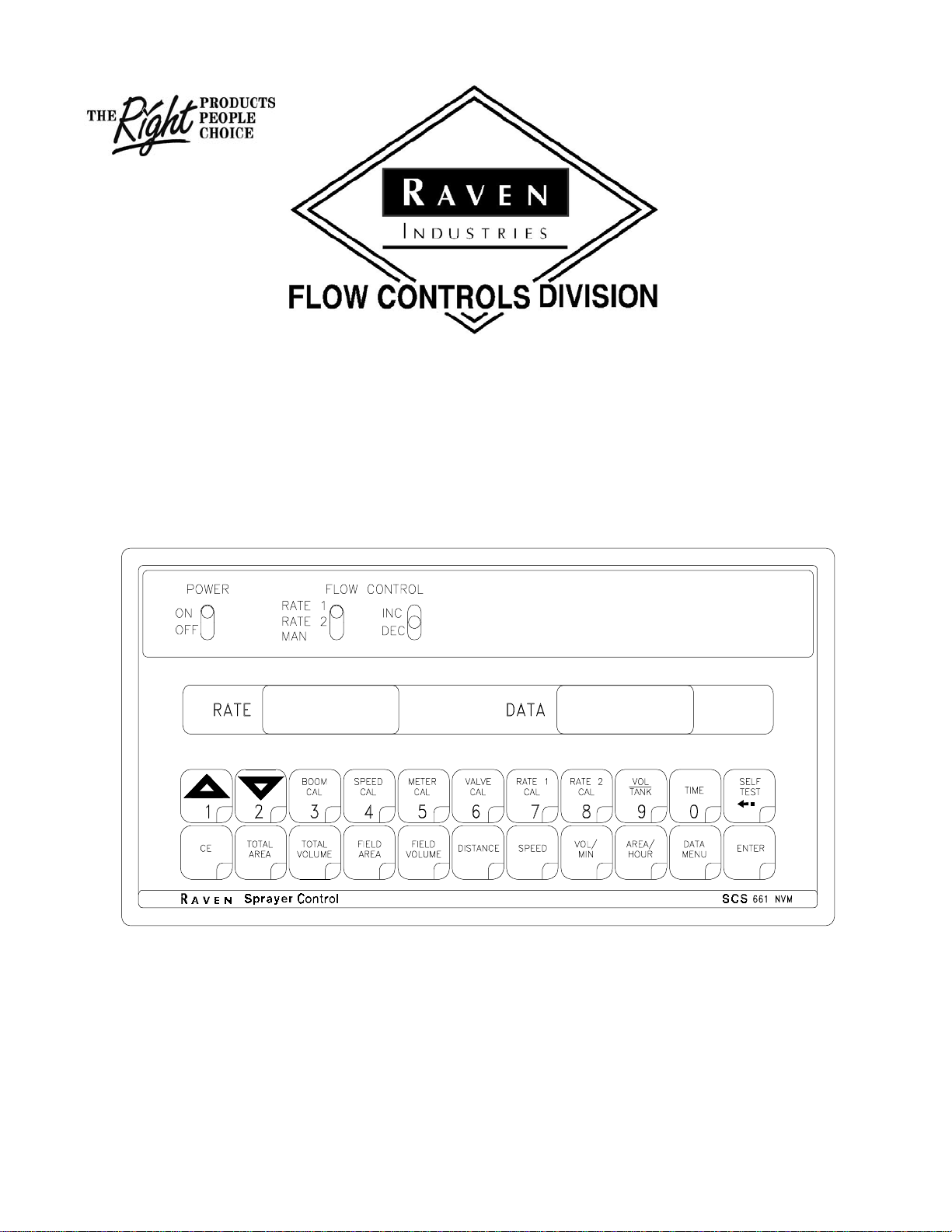
CONSOLE FEATURES........................................................................................................11
CONSOLECALIBRATION....................................................................................................12
1. CALCULATING "BOOM CAL".....................................................................................12
2.BOOMCALIBRATION .................................................................................................12
3. CALCULATING "SPEED CAL"...................................................................................13
4. CALCULATING "METER CAL" ...................................................................................13
5. CALCULATING "SPREADER CONSTANT" ...............................................................14
6. CALCULATING "VALVE CAL"....................................................................................15
7. CALCULATING "RATE 1 AND RATE 2 CAL" .............................................................16
CONSOLEPROGRAMMING................................................................................................18
1.INITIALCONSOLEPROGRAMMING ..........................................................................19
2. OTHER DISPLAY FEATURES ....................................................................................23
3. SELF TEST FEATURE ...............................................................................................23
4.VOLUME/MINUTERATEFAULT ................................................................................24
5. VOLUME/AREA RATE ALARM ..................................................................................24
6. LOW TANK FAULT......................................................................................................24
7.AUTOMATICRATE+/- ................................................................................................24
8. CONTROL VALVE DELAY .........................................................................................25
9. SEQUENCE TO ACTIVATE DATA-LOCK .................................................................. 25
10. SEQUENCE TO CHANGE DATA-LOCK .................................................................. 25
11. ENTER MODE SEQUENCE WITH ACTIVATED DATA-LOCK.................................25
12. DATA MENU .............................................................................................................26
13. DECIMAL SHIFT .......................................................................................................33
INITIALSYSTEMSET-UP .....................................................................................................34
INITIALSYSTEMFIELDTEST ..............................................................................................36
PREVENTIVEMAINTENANCE ............................................................................................36
TROUBLESHOOTINGGUIDE ..............................................................................................37
016-0159-744
07/02

2
APPENDIXES
1. PROCEDURE TO TEST SPEED SENSOR EXTENSION CABLES ................................40
2. PROCEDURE TO TEST FLOW METER CABLES...........................................................41
3. FLOWMETER MAINTENANCE AND ADJUSTMENT PROCEDURE ..............................42
4. PROCEDURE TO RE-CALIBRATE FLOW METER .........................................................43
5.FANRPMSENSORINSTALLATION ................................................................................44
6.BIN LEVELSENSOR INSTALLATION..............................................................................45
7. SERIAL INTERFACE ........................................................................................................46
8.SCS661COMMUNICATIONSTRINGS............................................................................47
9. VERIFICATIONOF SPREADERCONSTANT .................................................................. 48
10. WHEEL DRIVE SPEED SENSOR INSTALLATION & CALIBRATION PROCEDURE....49
11. SPEEDOMETER DRIVE SPEED SENSOR INSTALLATION AND CALIBRATION............
PROCEDURE .................................................................................................................52
REPLACEMENT PARTS SHEETS

3
SYMBOL DEFINITION (Liquid Applications)
METER CAL CONVERSIONS
To convert the METER CAL number simply divide the original number (number printed on Flow
Meter label) by the desired conversion factor.
FOR EXAMPLE:
Original METER CAL No. = METER CAL No. for displays in Fluid Ounces
128
Original METER CAL No. = METER CAL No. for displays in Liters
3.785
Original METER CAL No. = METER CAL No. for displays in Pounds
Weight of one gallon
LIQUID CONVERSIONS
U.S. Gallons x 128 = Fluid Ounces
U.S. Gallons x 3.785 = Liters
U.S. Gallons x 0.83267 = Imperial Gallons
U.S. Gallons x 8.34 = Pounds (Water)
LENGTH
1 millimeter (mm) = 0.039 inch
1 centimeter (cm) = 0.393 inch
1 meter (m) = 3.281 feet
1 kilometer (km) = 0.621 mile
1 inch = 25.4 millimeters; 2.54 centimeters
1 mile = 1.609 kilometers
PRESSURE
1 psi = 6.89 kPa
1 kPa = 0.145 psi
AREA
1 square meter = 10.764 square feet
1 hectare (ha) = 2.471 acres; 10,000 square meters
1 acre = 0.405 hectare; 43,560 square feet
1 square mile = 640 acres; 258.9 hectares
GPM - Gallons per minute
lit/min - Liters per minute
dl/min - Deciliter per minute
PSI - Pounds per square inch
kPa - Kilopascal
GPA - Gallon per acre
lit/ha - Liter per hectare
ml/ha - Milliliter per hectare
GPK - Gallons per 1,000 sq. ft.
mm - Millimeters
cm - Centimeters
dm - Decimeters
m -Meter
MPH - Miles per hour
km - Kilometers
km/h - Kilometers per hour
US - Volume per acre
SI - Volume per hectare
TU - Volume per 1,000 sq. ft.
[] - Metric numbers
{} - 1,000 sq. ft. numbers

4
SYMBOL DEFINITION (Granular Application)
DRY CONVERSIONS
Kilograms x 2.2 = Pounds
Pounds x .455 = Kilograms
LENGTH
1 millimeter (mm) = 0.039 inch
1 centimeter (cm) = 0.393 inch
1 meter (m) = 3.281 feet
1 kilometer (km) = 0.621 mile
1 inch = 25.4 millimeters; 2.54 centimeters
1 mile = 1.609 kilometers
AREA
1 square meter = 10.764 square feet
1 hectare (ha) = 2.471 acres; 10,000 square meters
1 acre = 0.405 hectare; 43,560 square feet
1 square mile = 640 acres; 258.9 hectares
VOLUME
1 cubic meter = 1000 liters
1 cubic centimeter = 1 milliliter
PPM - Pounds per minute
kg/min - Kilograms per minute
PPA - Pounds per acre
kg/ha - Kilograms per hectare
PPK - Pounds per 1,000 sq. ft.
mm - Millimeters
cm - Centimeters
dm - Decimeters
m -Meter
MPH - Miles per hour
km - Kilometers
km/h - Kilometers per hour
US - Volume per acre
SI - Volume per hectare
TU - Volume per 1,000 sq. ft.
[] - Metric numbers
{} - 1,000 sq. ft. numbers

5
INTRODUCTION
The Raven SCS 661 (CONTROL SYSTEM) is designed to improve the uniformity of spray and granular
applications. Its performance relies on installation and preventive maintenance of the complete sprayer or
spreader. It is important that this Installation and Service Manual be reviewed thoroughly before operating
the system. This manual provides a simple step-by-step procedure for installing and operating.
The SCS 661 liquid system consists of a Control Console, a Speed Sensor, a turbine type Flow Meter, and
a motorized Control Valve. The SCS 661 granular system consists of a Control Console, a Speed Sensor,
an Encoder, and a Hydraulic Control Valve. The Console mounts directly in the cab of the vehicle for easy
operator use. The Radar Speed Sensor is mounted to the frame of the tractor or sprayer (Other Speed
Sensors are also available). For liquid systems the Motorized Control Valve and Flow Meter mount to the
framework supporting the Boom Valves. For granular systems, the Hydraulic Control Valve mounts to the
framework of the vehicle and the Encoder mounts to the conveyor drive shaft. Appropriate cabling is
furnished for field installation.
The operator sets the target volume per area to be sprayed or weight per area to be applied and the SCS
661 automatically maintains the correct application rate regardless of vehicle speed or gear selection. A
manual override switch allows the operator to manually control the rate for system checkout and spot
application. Actual volume or weight per area being applied is displayed at all times. The SCS 661
additionally functions as an area monitor, speed monitor, and volume totalizer.
NOTE: The SCS 661 Control Console is designed to be used with external Boom
switches. Inorder for the Console to know when andwhichBoomisON or OFF,
Boom signal wires are provided.

6
INSTALLATION
1. MOUNTING THE RAVEN RADAR SPEED SENSOR
For mounting the radar, the following guidelines will assure proper installation:
It is suggested that a large heavy mounting bracket, (P/N 107-0159-693) be attached to the vehicle
frame for mounting the radar.
1) Park vehicle on level surface.
2) Select mounting site by considering the following:
a) The line of sight from the lens to the ground must not be obstructed by structures or tires.
Obstructions must not come closer than 20 inches to the bottom of the radar. See Figures
1 and 2.
b) The radar lens must be parallel to the ground from front to back. Radar can be tilted out 0-
15 degrees to provide more clearance and miss obstructions. See Figure 2.
c) The radar should be mounted so that the length of the radar is parallel with direction of
vehicle travel.
3) Use carpenters level to verify that mounting bracket is parallel to the ground.
4) Bolt mounting bracket to implement.
5) Bolt radar to mounting bracket using mounting hardware. See Figure 3.
6) ConnectradarwithRadarInterfaceCable(P/N115-0159-539),totheConsole. TheRedwireshould
be connected to the Orange cable wire. The White wire should be connected to the White cable
wire (See "BATTERY CONNECTIONS").
CAUTION: The connection of the radar power in reverse polarity could result in damage to
the radar.
FIGURE 1 FIGURE 3
FIGURE 2

7
2. MOUNTING THE FLOW METER (Liquid Applications)
1) Mount Flow Meter in the area of the boom valves per Figure 4. All flow through Flow Meter must go
to booms only, i.e., no return line to tank or pump after Flow Meter.
2) Mount Flow Meter horizontal to the ground. Use the bracket to secure the Flow Meter.
3) For best results, allow a minimum of 7 1/2 inches [20 cm] of straight hose on inlet of Flow Meter.
Bend radius of hose on outlet of Flow Meter should be gradual.
4) Flow must be in direction of arrow on Flow Meter.
3. MOUNTING THE CONTROL VALVE (Liquid Applications)
1) Mount the motorized Control Valve in the main hose line between the Flow Meter and the booms,
with motor in the upright position.
2) Connect the Vehicle Cable connectors to boom valves, Flow Meter, and motorized Control Valve.
(Blackwiretoboomvalve#1,Browntoboomvalve#2,Bluetoboomvalve#3,Blk/whttoboomvalve
#4,Brn/wht toboomvalve #5, Blu/whttoboom valve #6,Wht/blkto boom valve#7,wht/brn to boom
valve #8, wht/blue to boom valve #9, pink to boom valve #10).
NOTE: It is critical, when using suspensions, that the system be thoroughly rinsed out
each day after use.
FIGURE 4

8
4. MOUNTING THE ENCODER (Granular Applications)
1) Mount Encoder on output shaft of conveyor, or other shaft which rotates at a known ratio to the
conveyor. (See Figures 6,7, 8 & 9).
2) Apply grease to Encoder shaft, conveyor shaft, and Encoder coupler (fits 1" diameter conveyor
shaft). Secure coupler to Encoder and conveyor shafts with set screws provided.
3) Install mounting tabs to Encoder as shown in Figure 5. Connect mounting tab to mounting bracket
(not provided) to prevent Encoder from rotating. DO NOT rigidly mount Encoder. Encoder is to be
supported by coupler ONLY.
FIGURE 5

9
5. MOUNTING THE HYDRAULIC CONTROL VALVE (Granular
Applications)
1) Refer to Figures 6,7, 8 & 9 for typical placement of the Hydraulic Control Valve.
2) Valve is to be mounted with motor in the upright position.
PNEUMATIC SYSTEM
SPINNER SYSTEM
CLOSED HYDRAULIC SYSTEM (VARIABLE DISP. PUMP)
FIGURE 9FIGURE 8
FIGURE 7
FIGURE 6
OPEN HYDRAULIC SYSTEM (FIXED DISP. PUMP) CLOSED HYDRAULIC SYSTEM (VARIABLE DISP. PUMP)
OPEN HYDRAULIC SYSTEM (FIXED DISP. PUMP)

10
6. MOUNTING THE CONSOLE AND CABLING
1) Mount the Console and Switch Box to a secure support inside the cab of the vehicle.
2) Connect the Console Control Cable to the plug in the back of the Console. (See Figure 10). Route
the Console Control Cable out of the vehicle cab and connect with vehicle connectors.
FIGURE 10
3) Secure Console Control Cable with plastic cable ties.
4) Initial installation of the system is now complete.

11
CONSOLE FEATURES
IMPORTANT:This Console requires selection of US (acres), SI [hectares], or TU {1,000 sq.
ft.}area; SP1 (wheel drive,etc.)orSP2 (radar) speed sensor;LI (liquidsprayer),
GR1 (singlebeltbed),GR2 (splitbeltbed),orGR3 (splitbeltbed,dualencoder);
and C-Sd (Standard Valve), C-F (Fast Valve), C-FC (Fast Close Valve), and
C-P (PWM Valve).
POWER-TurnsConsolepowerONorOFF.
Turning Console OFF does not affect the
data stored in the computer.
CE-ExitsENTERmodeandisalsousedto
select the features listed in IMPORTANT
boxabove.
Displays actual rate of application and
other messages.
Displaysfunctionandcalibrationdata.
Manualoverridecontrolprovidescapability
for spot applications.
Selects manual or fully automatic control.
ConsoleRevisioncanbedeterminedbyletter stamped
in REV box on label.
ConsoleProgramcanbedeterminedbyletter stamped
in PGM box on label.
CALIBRATIONKEYS-- Used to enter data into the
Console to calibrate the
system.
BOOM CAL -- Width of Boom 1-10. Select
Boom number by using the
UP/DOWN arrow keys.
SPEEDCAL -- Determined by Speed Sensor
METERCAL -- Meter Calibration Number
VALVE CAL -- Valve Response Time
RATE 1 CAL -- Target Application Rate
RATE 2 CAL -- Target Application Rate
VOL/TANK -- Volume in Tank
TIME -- Time/Date features
SELFTEST -- Simulates Vehicle Speed
063-XXXX-XXX
FUNCTIONKEYS -- Used to Display Data
TOTAL AREA -- Total Area Applied
TOTALVOLUME -- Total Volume Applied
FIELDAREA -- Field Area Applied
FIELDVOLUME -- Field Volume
DISTANCE -- Distance Traveled
SPEED -- Speed of Vehicle
VOL/MIN -- Volume Per Minute
AREA/HOUR -- Area per Hour
DATAMENU -- Various options
ENTER -Used only to enter data into the
Console.

12
CONSOLE CALIBRATION
1. CALCULATING “BOOM CAL”
Calculate the width of each boom in inches (cm) by multiplying the number of tips time the spacing.
Write these boom widths down for future reference when programming the Console.
2. BOOMCALIBRATION
Definition of Boom Calibration keys for a Boom system.
Depressing this key, displays selected boom number in DATA display.
EXAMPLE: Left Boom will be displayed as b-01, and Right Boom will be displayed as
b-10 if all 10 Booms are used.
Depressing this key after selecting BOOM CAL, changes the boom number.
EXAMPLE: b-01 will change to b-02.
Depressing this key after selecting BOOM CAL, changes the boom number.
EXAMPLE: b-02 will change to b-01.
Entering Boom Data:
1. Select desired boom number.
2. Enter boom length as detailed under CALCULATING “BOOM CAL” section.
3. If a boom is not used, enter a “0” for that length.
BOON 1 - BLACK
BOOM 2 - BROWN
BOOM 3 - BLUE
BOOM 4 - BLK/WHT
BOOM 5 - BRN/WHT
BOOM 6 - BLU/WHT
BOOM 7 - WHT/BLK
BOOM 8 - WHT/BRN
BOOM 9 - WHT/BLU
BOOM10-PINK
TYPICAL PLUMBING DIAGRAM

13
3. CALCULATING "SPEED CAL"
Initial SPEED CAL is 598 [152]. Complete Steps 1 thru 6 to refine this number after "INITIAL
CONSOLE PROGRAMMING" has been completed.
1) Set POWER switches to ON, all other switches to OFF.
2) Enter "0" in key labelled:
3) Drive 1 mile [1 kilometer]. To achieve the most accurate calibration, accelerate and decelerate
slowly.
CAUTION: Do not use vehicle odometer to determine distance. Use section lines or
highway markers.
4) Read DISTANCE by depressing key labelled:
DISTANCEshouldreadavalueofapproximately5280[1000]. Ifitreadsbetween5260-5300[990-
1010],theSPEEDCAL forthe vehicleis598 [152]. Ifthe DISTANCEdisplayreadsanyother value,
perform the following calculation:
EXAMPLE: Assume DISTANCE reads 5000 [980].
Corrected SPEED CAL = Old SPEED CAL x 5280
DISTANCE
ENGLISH UNITS: METRIC UNITS:
= 598 x 5280 = 631.48 = [152] x [1000] = [155]
5000 [980]
5) The number to enter for SPEED CAL is 631 [155].
6) Recheck the new SPEED CAL derived in Step 5 by repeating Steps 2 thru 5.
4. CALCULATING"METER CAL"
LIQUID APPLICATIONS
1) When calculating METER CAL refer to the Flow Meter calibration number which is stamped on the
label attached to the Flow Meter. This number is to be used for gallon per area applications.
Toconvertoriginal METER CAL from gallons to desired unitsof measure(oz, lbs,or liters perarea)
see "METER CAL CONVERSIONS".
Write down this calibration number for future reference when programming the Console.
GRANULAR APPLICATIONS
Product density in lbs/cu.ft. [grams/liter] is entered as METER CAL.
NOTE: To increase the system accuracy when applying at low rates, use the
decimal shift feature as explained in CONSOLE PROGRAMMING.

14
5. CALCULATING "SPREADER CONSTANT" (Granular Appli-
cations)
1) For RATE displayed in 1 lb [1 kg] increments:
L = Length in inches [centimeters], of belt travel per 1 revolution of Sensor
GH = Gate Height in inches [centimeters]
GW = Gate Width in inches [centimeters]
CPR = Counts per 1 revolution of sensor
English (US) : Metric(SI):
Spreader Constant = CPR x 1728 Spreader Constant = [CPR x 100,000]
(1 lb) L x GH x GW (1 kg) [L] x [GH] x [GW]
EXAMPLE: 1) L = 13 inches [33 cm]
2) GH = 7 inches [18 cm]
3) GW = 15 inches [38 cm]
4) CPR = 180
English (US):
Spreader Constant (1 lb) = 180 x 1728
13 x 7 x 15
=311,140 = 228
1365
Metric (SI):
Spreader Constant (1 kg) = [180 x 100,000]
[33] x [18] x [38]
=[18,000,000] = [797]
[22,572]
Counts per one revolution of sensor (CPR) may be determined by entering a METER CAL of 10, enter 0
inTOTALVOLUMEandturningsensorexactlyonerevolution. ThenumberinTOTALVOLUMEwillbethe
CPR. Thiscalculation canbeperformed whiledetermininglength ofbelttravel peronerevolution of sensor
(L).
NOTE: Verify Spreader Constant by performing Spreader Constant calibration proce-
dure in Appendix 9 before field application.
Table of contents
Other Raven Control Unit manuals
Popular Control Unit manuals by other brands

Novanta
Novanta JADAK THINGMAGIC EL6E Getting started

Solid Technologies
Solid Technologies HERCULES user manual

Sony
Sony MB0402C2 user manual

Erica Synths
Erica Synths Black Series GUIDE ON ASSEMBLY

CHENGDU VANTRON TECHNOLOGY
CHENGDU VANTRON TECHNOLOGY AP6255 user manual

ensto
ensto ECO900 operation instruction