Raw Desigh PowerPUC G4 User manual

METRICFATS.COM!
Thank&you&for&purchasing&your&new&POWER8PUC™!Wheel&Lighting&Kit.&
The instructional sheets that follow are thoroughly detailed and should be studied
BEFORE picking up a tool. Take your time, work safe and you will enjoy your new
POWER-PUC™ Wheel Lights within a few hours.
ATTENTION: You should ALWAYS disconnect your battery before performing any
electrical work.
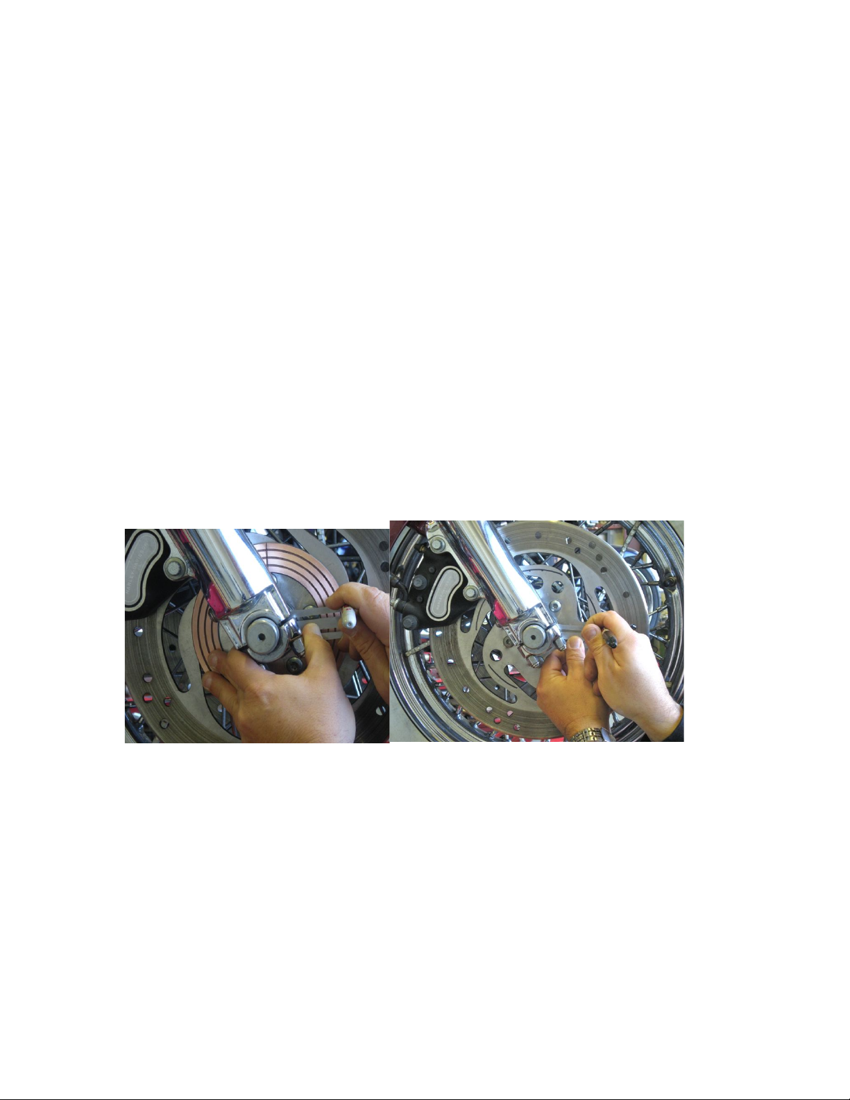
Although the following instructions show a particular make and model of bike, virtually
every installation process will be identical regardless of bike. Also, the bike shown has a
completely flat rotor. Yours may be different. Not to worry. POWER-PUCs are made to
fit your particular bike. In some cases you may find it easier to install the rear PUC on the
drive sprocket or pulley instead of the rotor (recommended location is normally marked
on packaging). As long as you have read the following instructions and are aware of the
general operation of the system, you should have no problem. Lastly, these instructions
address installation of the PUCs themselves. Because of almost limitless combinations,
detailed instructions for installation of LEDs on the wheels is impractical. However, there
may be a future article on some simple layouts. But if you have a basic knowledge of 12
volt wiring and use some common sense you should not have any issue installing LEDs.
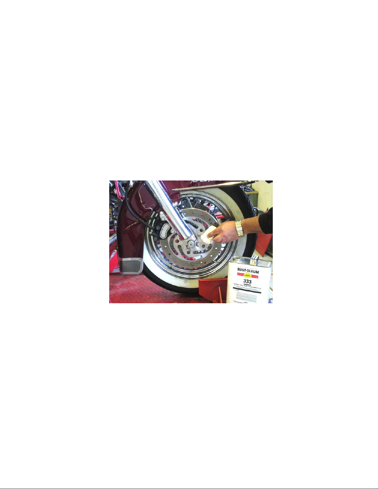
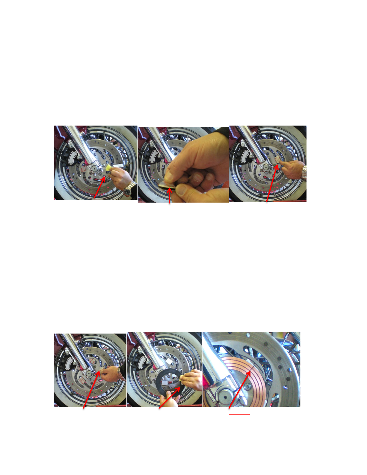
Just remember, ANYWHERE you will be using double-stick tape, the surface
MUST be perfectly clean. Also, all wires, LEDs etc. that are on the wheels must be
thoroughly restrained.
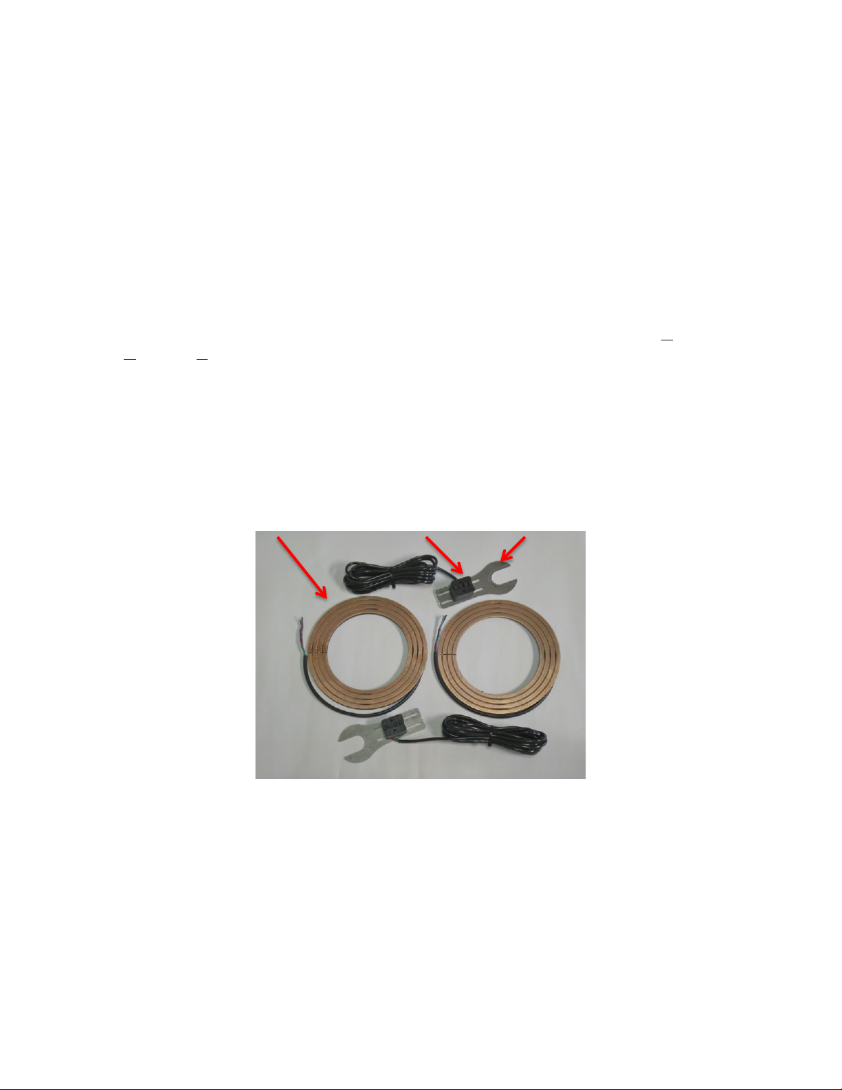
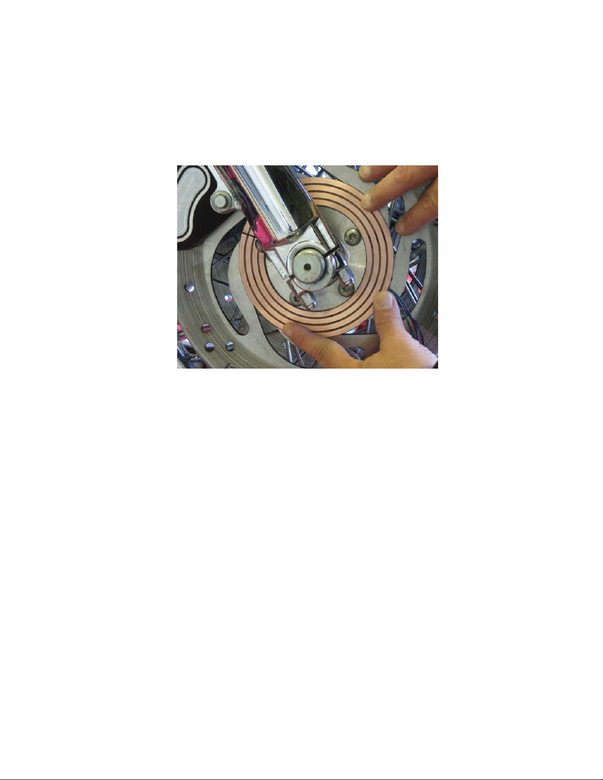
Let’s get familiar with the kit and how it works.
(Pictures are representative only. Your PUCs may be of different sizes)

The G4 PUC
Our New G4 POWER-PUC™ is a substantial advancement in RAW Design’s (Patent
Pending) Wheel Lighting Systems.
Below is a picture of the system. The 2 copper colored rings are the “PUCs”. The PUCs
are mounted directly on the wheels (…actually rotor, pulley or sprocket) and will
obviously spin with the wheels. Each PUC has 4 contact rings. Individual wires attached
to each ring exit the back of the PUC and will latter be connected to your wheel mounted
LEDs. 4 rings give several control options, as well as the ability to use color-changing
lights. Color changing lights are also referred to as “RGB” lights. This stands for Red,
Green and Blue. Any of these colors either by themselves, or in different combinations,
will create almost any color.
Also shown are the 2 Brush Housings (black) and Universal Mounts (silver).
Each Brush Housing has 4, spring loaded brushes and each brush is connected to a wire.
These wires will then be connected to a controller(s) and the bikes battery.
Once everything is installed, electrical power from the bikes battery will flow through the
4 brushes to the 4 rings of the PUC and to the LEDs.
PUC Brush Housing Universal Mount

The PUC and Brush Holder’s wiring is color coded and matched. This will become
important if you are using RGB LEDs or want to experiment with some advanced effects
(Don’t ask. If you’ve got the electrical experience, you’ll see the possibilities and figure it
out)
The order of the wires as they come out of the Brush Holder are Black, Red, Green, Blue.
This matches to the PUC…Black (-) is the outermost ring, then Red, Green and Blue as
you move towards the center. You may want to come back and reference this latter.
Black Red Green Blue

Installation
Part 1: locating the PUC
In general, it will be easier to work if you get the wheel slightly off the ground.
Because it was easier to photograph, these instructions show the system being mounted to
the “profile” side of the bike. This means it is the right side (as seated) of the bike that is
easiest to see when it is on the kickstand. In most instances it is best to mount the
system on the “non-profile” (left) side. This will make it less apparent to most
observers and they will be scratching their heads wondering how it all works.
For several reasons (You’ll see why later) an industrial grade Velcro with a double-stick
backing is used to mount your PUC. So for the front wheel, clean the rotor with Acetone
or some other degreaser that will not leave any type of film behind.

Next, you’ll need to create a small gap between the wheel spacer and fork in order to
install the Universal Mount. To do this, loosen the axle bolts / clamps just a few turns.
Sometimes, the side you loosen will be where the gap naturally shows up. Other times it
will be the opposite side. Regardless, since we want the gap on the kickstand side of the
bike, you may have to lightly tap the axle with a rubber hammer or piece of wood to shift
the gap to that side. You can see the axle nut, axle clamp and small gap we created,
below.
Axle Nut Axle Clamp Gap
Different bikes have different axle sizes. Our Universal Mount should fit all known
applications.
The “U” portion is what will slip into the gap you just created and over the axle. Try it.
If the “U” is too small, you can remove the inner section by clipping the connectors at the
top of the “U” with a pair of snips. Then just move the inner piece back and forth and the
last connector at the bottom of the “U” will break off. It should now fit. Put it aside for
now.
Connectors

Pick up one of the PUCs and examine it. You will see it has a split as shown below.
There is an interlocking notch on either side of the split.
Forget about double stick or Velcro for now. Take the split ring and “screw” it over the
fork like is shown in the lower left picture.
DO NOT OVER-BEND THE RING!! It will need to be as flat as possible at the end of
the installation. Minor bends (more like slight curves) can be adjusted by hand at final
fitting, but if you put a “crease”, crack of break it…game over and you’ll need a new
ring.

It’s very important that the ring be concentric, or centered, on the wheel within about
1/16”. On most bikes there is an existing feature of the wheel that will substantially help
you with this. It can be an existing bolt pattern, shoulder of some sort, or other natural
feature on the wheel. The correct feature will vary between manufacturers and models.
In the picture below, you see we can use the bolt pattern as our guide. It will become
fairly apparent what feature you should use on your wheels once the PUC is next to the
wheel.
It is also possible that the PUC will mount over the rotor bolts in some applications.
This is another reason for using the velcro – to allow easy removal of the PUC and access
to these bolts. When mounted, the velcro will act as a spacer between the rotor and PUC
and clear the bolts.

If you can mount your PUC with one of the “natural” alignment features mentioned
above - great. On rare occasions where no natural features exist, you can create your own.
It will be like putting a Dime on top of a Quarter and just making sure the dime is
centered. Start by drawing a circle on the wheel by doing the following:
Hold the ring on the wheel and center it as best as possible. Use a Sharpe to place a small
mark on the wheel where the inside or outside of the ring sit. The picture below-left
shows this. The Universal Mounting fork can then be used to mark a concentric circle
that can be used as your “feature”.
Insert the mounting fork into the gap you created earlier and MAKE SURE it is all the
way (bottomed) against the axle. The fork is not designed to be a snug fit around the axle,
but if the “U” is bottomed against the axle, it will offer a consistent baseline to work
from.
Notice that the mount has a series of notches. This is to act as guide for the Sharpe or
pencil. So while holding the Sharpe / pencil on a groove of the mounting fork and against
the rotor, have someone slowly rotate the wheel until you have a full circle marked. You
now have a “Feature”.

PART 2: Mounting the PUC
Cut lengths of the included velcro strip into sections that are about 1/8” longer than the
width of the PUC. A good pair of scissors works well. Do this while the 2 halfs of the
Velcro strips are together - and keep them that way. Don’t pull them apart. You should
get about 5 pieces. Don’t worry if they are not exactly the same length.
You will want to space the Velcro sections evenly around the rotor and also put them in
areas where you will get the most surface contact between the rotor and Velcro pieces.
More surface area = better adhesion. Take some time to examine and decide on this, then
clean the area one more time. Be careful not to erase your reference lines. Remember to
place the Velcro along the reference line(s) you drew.

There is a foil pack of adhesive promoter included in your kit. Once you know where the
Velcro will mount, tear off a corner of the pack and pull a section of the applicator out
without removing it. Wipe the entire area with the promoter, peel the protective film from
the double-stick on one side of the Velcro and apply to the rotor. Press and hold it there
for a minute while working all the edges against the rotor. It is best that this is done while
the promoter is still wet. That’s why you are reading these instructions all the way
through before starting. Right? So you will know what to expect and be ready.
Apply adhesive promoter Peel protective film Work strip onto wheel.
When you are done with the promoter, push it back into the foil pack and fold an edge of
the pack over. This will keep the promoter from drying out until you need it again.
The same process is used for applying the PUC to the Velcro, EXCEPT…the split in
the ring must be in the middle of one of the Velcro sections!! This is extremely
important as it aligns the edges of the split. Failure to do so WILL (not might) result in
damage.
Peel the protective film from the back of the Velcro, clean the back of the PUC and apply
the adhesive promoter. Use the natural features mentioned previously, or reference lines
you marked to set the PUC on the Velcro. Again, use pressure to make sure it is seated.
DO NOT TRY AND SEPARATE THE VELCRO BY PULLING ON THE PUC!!! If
you need to make an adjustment we will get to that in a minute, so just leave it alone for
now and let the adhesive set.
Remove film Clean & primer PUC Split MUST be on Velcro

For the moment, get the PUC wires out of the way so you will be able to spin the wheel
without them getting caught anywhere. Tuck them inside and add a piece of tape to hold
them there.
Step 3. Checking concentricity (alignment).
Making sure the PUC is concentric with the wheel is very important. Failure to do so can
result in damage to the system.
If you were able to mount your PUC with one of the “natural” alignment features
previously mentioned, this “Checking concentricity” section is most likely unnecessary to
actually perform. BUT READ IT ANYWAY! We are probably over-explaining the
process, but there’s no danger of being over-educated and it may help you someplace else
at another time.
We’ve intentionally misaligned the PUC below to show you how to adjust it if necessary.
It’s basically the same process as when you marked the rotor, but this time you will be
marking the PUC itself.

First, draw lines at the 12, 3, 6 & 9 o’clock positions.
Put the mounting bracket back on and make sure it’s seated against the axle.
Pick a tooth on the mount and use it as a guide again to mark a line as you rotate the
wheel. It may be a little difficult to see, but look close at the below picture and you’ll
notice the PUC is out of alignment by about the width of one contact ring, between the 3
& 9 o’clock positions. The 12 & 6 o’clock positions look pretty good. Even if they
weren’t, you should only adjust between 3 & 9 OR 12 & 6, one at a time.

New line showing misalignment

At the 9 o’clock position, the line we drew is on the inside edge of the outermost ring.
The 3 o’clock position in the right picture shows the line on the inside edge of the second
ring.
Notice Difference. They need to be the same.
We can see the PUC needs to move towards the 9 o’clock position, so we’ve marked the
rotor at the edge of the PUC to again use as a reference. (See below)
If you’ve applied the Velcro and double-stick properly, now’s the time you’ll see how
secure of an attachment this is.

Slide the Universal Mount off again just to make it easier to work. CAREFULLY work
your way around the PUC and use your fingertips to separate the Velcro halves while
making sure not to separate the velcro from the rotor or PUC. Do a little at a time to
prevent bending the PUC.
New reference mark on rotor

In this picture, notice the wider space to the left of the most recent reference mark we put
on the rotor. That’s because we moved the PUC slightly (one ring width) towards the 9
o’clock position and put the mount back in place to check everything. Notice how the
mounts’ second groove from the right lines up with the outside edge of the PUC. Look at
the next 2 pictures and you will see the alignment stays almost perfect as we rotate the
wheel to the 12 & 9 o’clock positions.
This process would be the same if you now had to adjust in the 12-6 o’clock positions.
But remember, only do one direction at a time.
Distance moved
Alignment check, 3 o’clock position

Alignment check, 12 o’clock position (Good)

Alignment check, 9 o’clock position (Still good)

Step 4. Mounting the Brush Housing
Now it’s time to mount the Brush Housing. Let’s take a closer look for a minute and see
exactly how it works. If you understand what you are working with it’s less likely you
will make a mistake.
The Housing is made so it can be removed from the mount with 2 screws. DO NOT try
to disassemble the brush unit itself as it is sealed during assembly at the factory.
There are 4 spring-loaded brushes (contactors) in each housing. When you receive your
kit, there will be a triangular shipping cover over the brushes to keep them compressed
during shipping. You can remove this cover when you are ready for installation. (Discard
the shipping cover screws and DO NOT use them)
While working with this during assembly on the bike, pay special attention that the
brushes are inside the housing enough that they move easily. They can sometimes extend
to the very edge of the housing and bind. Brushes are fragile and will break if given
minor force in anything other than their intended direction. In this case, “intended
direction” is straight in and out of the housing.
Also take notice of the way the housing is attached to the mount. There is a concave
radius on one end that should always be the side that faces the “Y” of the mount. This is
critical to spacing on some bikes, and critical to wiring on ALL bikes. Got that?
Universal Mount Brush Housing Brushes Concave side to face “Y”

The universal bracket fits every bike we’ve run across so far. “Universal” means you
have to do a little work to fit your particular bike (Very little though. About 15 minutes
worth.) Here’s how.
Since the Brush Housing contains spring-loaded brushes, there needs to be a consistent
space between the housing and PUC. You can use one of the wire ties that came with the
kit as a gauge for this. You may also have to bend the mount to get the position right. The
following shows how to accomplish all this. (You may need 3 hands for this next part)
Place the mount in the gap (Yes…again) created at the very beginning of the install and
as usual, make sure it is completely seated against the axle. Now take a wire-tie and place
it with the thinnest side creating the gauge, against the PUC. Take the Brush Housing and
place the brushes against the PUC. The brushes will contact the ring first. Then compress
the housing towards the ring until it touches the wire tire.
Brush Housing Universal Mount Wire tie PUC
Table of contents