Table of contents
Section 1 Introduction.......................................................................3
This manual........................................................................................3
Intended audience..............................................................................3
Product documentation.......................................................................4
Product documentation set............................................................4
Document revision history.............................................................5
Related documentation..................................................................6
Document symbols and conventions..................................................6
Safety indication symbols..............................................................6
Document conventions..................................................................7
Functions, codes and symbols......................................................7
Section 2 REM615 overview............................................................9
Overview.............................................................................................9
Product version history..................................................................9
PCM600 and IED connectivity package version............................9
Operation functionality......................................................................10
Optional functions........................................................................10
Physical hardware............................................................................10
Local HMI.........................................................................................11
LCD.............................................................................................12
LEDs............................................................................................13
Keypad........................................................................................13
Web HMI...........................................................................................13
Authorization.....................................................................................14
Communication.................................................................................15
Section 3 REM615 variants............................................................17
REM615 variant list..........................................................................17
Presentation of standard configurations...........................................17
Standard configuration................................................................18
Terminal diagrams.......................................................................20
Connection diagrams...................................................................21
Standard configuration C for motor protection with current and
voltage based protection and measurements functions...................22
Applications.................................................................................22
Functions.....................................................................................22
Default I/O connections..........................................................23
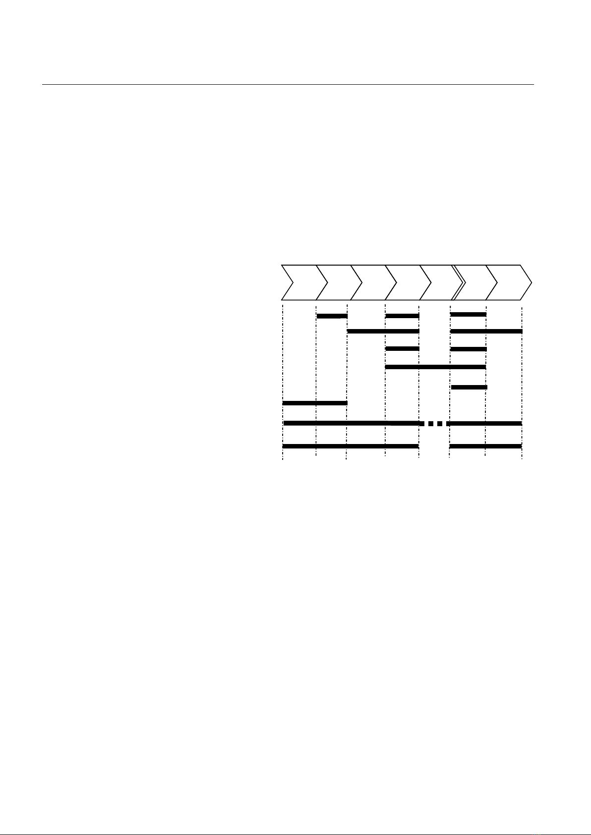
Functional diagrams....................................................................24
Functional diagrams for protection.........................................25
Table of contents
REM615 1
Application Manual