Raychem XL-Trace User manual
XL-Trace System
InstallatIon and operatIon manual for
pIpe freeze protectIon and flow
maIntenance
THERMAL MANAGEMENT WWW.PENTAIRTHERMAL.COM

ii
Raychem-IM-H58033-XLTracePipeFreezeProtectionCOM-EN 18/01
Important Safeguards and Warnings
WARNING: FIRE AND SHOCK HAZARD.
Raychem heat-tracing systems must be installed cor-
rectly to ensure proper operation and to prevent shock
and fire. Read these important warnings and carefully
follow all the installation instructions.
•To minimize the danger of fire from sustained electrical
arcing if the heating cable is damaged or improperly
installed, and to comply with Thermal Management
requirements, agency certifications, and national elec-
trical codes, ground-fault equipment protection must
be used on each heating cable branch circuit. Arcing
may not be stopped by conventional circuit breakers.
•Approvals and performance are based on the use of
Thermal Management-specified parts only. Do not sub-
stitute parts or use vinyl electrical tape.
•Bus wires will short if they contact each other. Keep
bus wires separated.
•Connection kits and cable ends must be kept dry before
and during installation.
•The black heating cable core is conductive and can
short. It must be properly insulated and kept dry.
•Damaged bus wires can overheat or short. Do not
break bus wire strands when preparing the cable for
connection.
•Damaged heating cable can cause electrical arcing or
fire. Do not use metal attachments such as pipe straps
or tie wire. Use only Thermal Management approved
tapes and cable ties to secure the cable to the pipe.
•Do not attempt to repair or energize damaged heating
cable. Remove damaged sections at once and replace
them with a new length using the appropriate Raychem
splice kit. Replace damaged connection kits.
•Use only fire-resistant insulation materials such as
fiberglass wrap or flame-retardant foams.
Note: Pipes are shown without insulation for illustrative
purposes only. All pipe installations must be fully cov-
ered with thermal insulation.

iii
Raychem-IM-H58033-XLTracePipeFreezeProtectionCOM-EN 18/01
Table of Contents
1 General Information 1
1.1 UseoftheManual 1
1.2 XL-TraceApplications 2
1.3 SafetyGuidelines 2
1.4 Approvals 3
2 Installation Guidelines 4
2.1 HeatingCableStorage 4
2.2 Pre-InstallationChecks 4
2.3 HeatingCableInstallation 5
2.4 HeatingCableConnections 17
3 Thermal Insulation 25
3.1 InsulatingtheSystem 25
3.2 InsulationInstallation 25
4 Power Supply and Electrical Protection 28
4.1 VoltageRating 28
4.2 CircuitBreakerSizing 28
4.3 ElectricalLoading 28
4.4 Ground-FaultProtection 28
4.5 ImportantPowerSupplySafeguards 29
5 Control, Monitoring and Power Distribution 30
5.1 ControlSystems 30
5.2 PowerDistribution 33
6 Commissioning and Preventive Maintenance 36
6.1 Tests 36
7 Test Procedures 38
7.1 SystemTests 38
7.2 FaultLocationTests 43
8 Troubleshooting Guide 48
9 Appendix 50
10 Installation and Inspection Records 56

iv
Raychem-IM-H58033-XLTracePipeFreezeProtectionCOM-EN 18/01

1
Raychem-IM-H58033-XLTracePipeFreezeProtectionCOM-EN 18/01
1
General Information
1.1 Use of the Manual
ThismanualcoverstheinstallationofRaychem
XL-Traceself-regulatingheatingcablesandcon-
nectionsforcommercialconstructionpipesystems
inordinary(nonhazardous)areas.Themanualcov-
ersgeneralheatingcableinstallationprocedures
andspecificinstallationdetailsandshowsavailable
connectionkitsforthedifferentapplications.The
manualalsodiscussescontrols,testing,andperiodic
maintenance.
Thismanualassumesthattheproperheat-tracing
designhasbeencompletedaccordingtothePipe
FreezeProtectionandFlowMaintenanceDesign
Guide(H55838).Onlytheapplicationsdescribedin
Section1.2areapprovedbyThermalManagement
forXL-Tracesystemswhenusedwithapproved
Raychemconnectionkits.Theinstructionsinthis
manualandtheinstallationinstructionsincluded
withtheconnectionkits,controlsystems,powerdis-
tributionsystems,andaccessoriesmustbefollowed
fortheThermalManagementwarrantytoapply.
ContactyourThermalManagementrepresentative
forotherapplicationsandproducts.
Foradditionalinformation,contact:
Thermal Management
7433HarwinDrive
Houston,TX77036
USA
Tel: +1.800.545.6258
Tel: +1.650.216.1526
Fax: +1.800.527.5703
Fax: +1.650.474.7711
thermal.info@pentair.com
www.pentairthermal.com

2
Raychem-IM-H58033-XLTracePipeFreezeProtectionCOM-EN 18/01
1
General Information
1.2 XL-Trace Applications
XL-Traceheat-tracingsystemsareapprovedand
qualifiedfortheapplicationslistedbelow.
Freeze protection
• General water piping.Freezeprotection(40°F
(4°C)maintain)ofinsulatedmetallicorplastic
waterpiping.
• Sprinkler piping systems.Freezeprotection(40°F
(4°C)maintain)ofinsulatedmetallicstandpipes
andsupplypipingupto20".
Flow maintenance
• Greasy waste lines.Flowmaintenance(110°F
(43°C)maintain)ofinsulated-greasedisposal
lines.
• Fuel lines.Flowmaintenance(40°F(4°C)main-
tain)forinsulatedmetallicpipingcontaining#2
fueloil.
Forheatingcableapplicationsotherthanthoselisted
above,pleaseseeyourThermalManagementrepre-
sentativeorcallusat(800)545-6258.
1.3 Safety Guidelines
Aswithanyelectricalequipment,thesafetyandreli-
abilityofanysystemdependsonthequalityofthe
productsselectedandthemannerinwhichtheyare
installedandmaintained.Incorrectdesign,handling,
installation,ormaintenanceofanyofthesystem
connectionkitscoulddamagethesystemandmay
resultininadequateperformance,overheating,
electricshock,orfire.Tominimizetheserisksand
toensurethatthesystemperformsreliably,read
andcarefullyfollowtheinformation,warnings,and
instructionsinthisguide.
Payspecialattentiontothefollowing:
• Importantinstructionsaremarked Important
• Warningsaremarked WARNING

3
Raychem-IM-H58033-XLTracePipeFreezeProtectionCOM-EN 18/01
1
General Information
1.4 Approvals
XL-Traceheat-tracingsystemscarryagency
approvalsforthedifferentapplicationsshownin
Section1.2.Fordetailedinformationonwhich
approvalsarecarriedforthespecificapplica-
tion,refertothePipeFreezeProtectionandFlow
Maintenancedesignguide(H55838).
Warranty
ThermalManagementstandardlimitedwarranty
appliestoallproducts.
Anextensionofthelimitedwarrantyperiodtoten(10)
yearsfromthedateofinstallationisavailableifa
properlycompletedonlinewarrantyformissubmit-
tedwithinthirty(30)daysfromthedateofinstalla-
tion.Youcanaccessthecompletewarrantyonour
websiteatwww.pentairthermal.com.

4
Raychem-IM-H58033-XLTracePipeFreezeProtectionCOM-EN 18/01
2
Installation Guidelines
2.1 Heating Cable Storage
• Storetheheatingcableinaclean,drylocation.
Temperaturerange:0°F(–18°C)to140°F(60°C).
• Protecttheheatingcablefrommechanical
damage.
2.2 Pre-Installation Checks
Check materials received
Catalog number: 5, 8 or 12 XL — 1 or 2 -CR -CT
Power output (W/ft)
Product family
Voltage 1 = 120 Vac (only available for 5 or 8)
2 = 208–277 Vac (available for 5, 8, or 12)
Jacket type: Polyolefin or
Fluoropolymer
(Required for grease and fuel lines)
Figure 1: XL-Trace catalog number
• Reviewtheheatingcabledesignandcomparethe
listofmaterialstothecatalognumbersofthe
heatingcablesandconnectionkitsreceivedto
confirmthatthepropermaterialsareonsite.The
heatingcabletypeisprintedonitsjacket.
• Ensurethattheservicevoltageavailableiscorrect
fortheXL-Traceheatingcableselection.
• Inspecttheheatingcableandconnectionkitsto
ensurethereisnoin-transitdamage.
• Verifythesystemdesigndoesnotexceedthemax-
imumexposuretemperatureoftheheatingcable
5XL/8XL:150°F(65°C)12XL:185°F(85°C)
• Verifythattheheatingcablejacketsarenotdam-
agedbyconductingtheinsulationresistancetest
(refertoSection7)oneachreelofheatingcable.
Donotpowertheheatingcablewhenit’sonthe
reel.

5
Raychem-IM-H58033-XLTracePipeFreezeProtectionCOM-EN 18/01
2
Installation Guidelines
Check piping to be traced
• Makesureallmechanicalpipetesting(i.e.hydro-
statictesting/purging)iscompleteandthesystem
hasbeenclearedbytheclientfortracing.
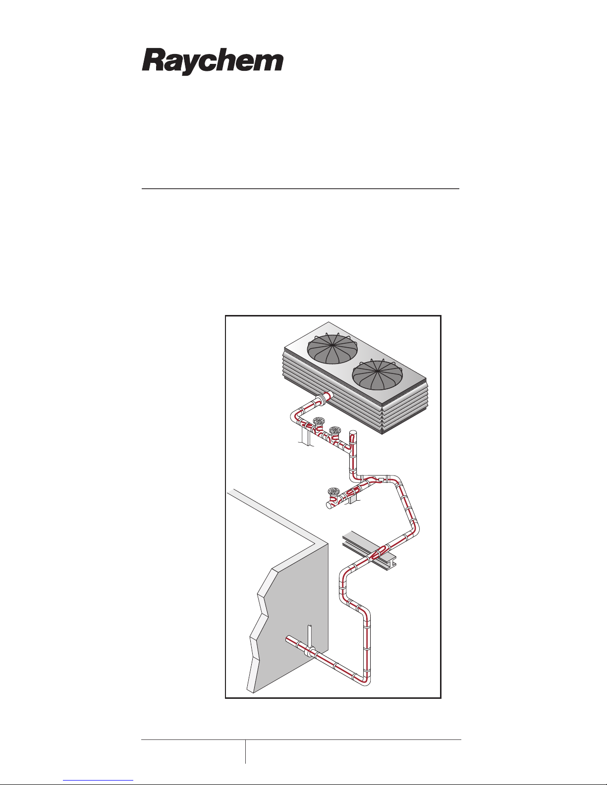
• Walkthesystemandplantheroutingoftheheat-
ingcableonthepipe.
• Inspectthepipingandremoveanyburrs,rough
surfaces,orsharpedges.
2.3 Heating Cable Installation
Minimuminstallationtemperatureof:0°F(–18°C).
Heatingcableinstallationinvolvesthreebasicsteps:
1. Payingouttheheatingcable
2. Attachingtheheatingcabletothepipe
3. Wrappingheatsinks
Paying out the heating cable
Mountthereelonaholderandplaceitneareither
endofthepiperuntobetraced.Useareelholder
thatpaysoutsmoothlywithlittletensionasshown
inFigure2.Avoidjerkingtheheatingcablewhile
pulling.
Payouttheheatingcableandlooselystringitalong
thepipe,makingsuretheheatingcableisalways
nexttothepipewhencrossingobstacles.Iftheheat-
ingcableisonthewrongsideofacrossingpipeor
I-beam,youwillhavetoreinstallitorcutandspliceit.

6
Raychem-IM-H58033-XLTracePipeFreezeProtectionCOM-EN 18/01
2
Installation Guidelines
Figure 2: Paying out the heating cable
When paying out the heating cable, AVOID:
• Sharpedges
• Excessivepullingforceorjerking
• Kinkingorcrushing
• Walkingonorrunningovertheheatingcablewith
equipment
WARNING: Fire and shock hazard. Do not install
damaged heating cable. Connection kits and heat-
ing cable ends must be kept dry before and during
installation.
Attaching the heating cable
Oncetheheatingcablehasbeenrunfortheentire
section,beginfasteningittothepipe.Startatthe
endandworktowardthereel.Theadditionalheat-
ingcablerequiredforvalvesandotherheatsinksis
showninTable1andTable2.RefertoTable3forthe
additionalheatingcablerequiredforconnectionkits.
Theheatingcablemaybeinstalledinsingleorin
multiplerunsasrequiredbythedesign.
7
Raychem-IM-H58033-XLTracePipeFreezeProtectionCOM-EN 18/01
2
Installation Guidelines
Figure 3: Attaching the heating cable

8
Raychem-IM-H58033-XLTracePipeFreezeProtectionCOM-EN 18/01
2
Installation Guidelines
TABLE 1:
ADDITIONAL HEATING CABLE FOR VALVES
Pipe diameter (IPS)
Heating cable in feet (meters)
1/2 0.8 (0.24)
3/4 1.3 (0.4)
1 2.0 (0.6)
1-1/4 3.3 (1.1)
1-1/2 4.3 (1.3)
2 4.3 (1.3)
3 4.3 (1.3)
4 4.3 (1.3)
6 5.0 (1.5)
8 5.0 (1.5)
10 5.6 (1.7)
12 5.9 (1.9)
14 7.3 (2.2)
18 9.4 (2.9)
20 10.5 (3.2)
TABLE 2:
ADDITIONAL HEATING CABLE FOR PIPE SUPPORTS
AND FLANGES
Support
Additional heating cable
Pipehangers(insulated) Noadditionalheatingcable
Pipehangersnoninsulatedand
U-boltsupports:
Add2xpipediameter
Weldedsupportshoes Add3xthelengthoftheshoe
Flanges Add2xpipediameter
Note:Forapplicationswheremorethanoneheatingcableis
requiredperfootofpipe,thiscorrectionfactorappliesforeach
heatingcablerun.
9
Raychem-IM-H58033-XLTracePipeFreezeProtectionCOM-EN 18/01
2
Installation Guidelines
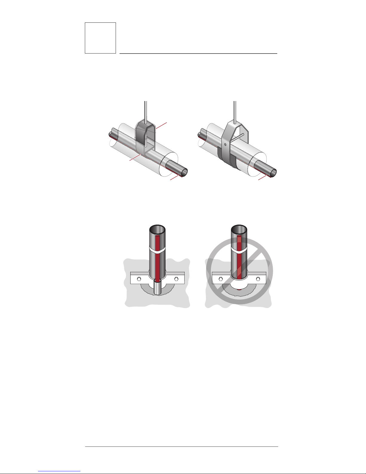
• Runinsulationthroughthepipehangerensuring
thatthepipeisnotrestingontheheater.
Heating cable
Heating cable
beneath
insulation
and pipe hanger
Heating cable
over pipe hanger
Pipe hanger
under insulation
Pipe hanger
over insulation
Insulation over
pipe hanger
Heating cable
Figure 4: Pipe hanger with heating cable
Figure 5: Single pipe floor penetration
• Whenmakingfloororwallpenetrations,make
suretheholeislargeenoughtoaccommodate
thepipeandthethermalinsulation.Whensealing
aroundpipesatfloorpenetrations,avoiddamag-
ingorcuttingtheheatingcable,orpinchingit
betweenthepipeandtheconcrete.
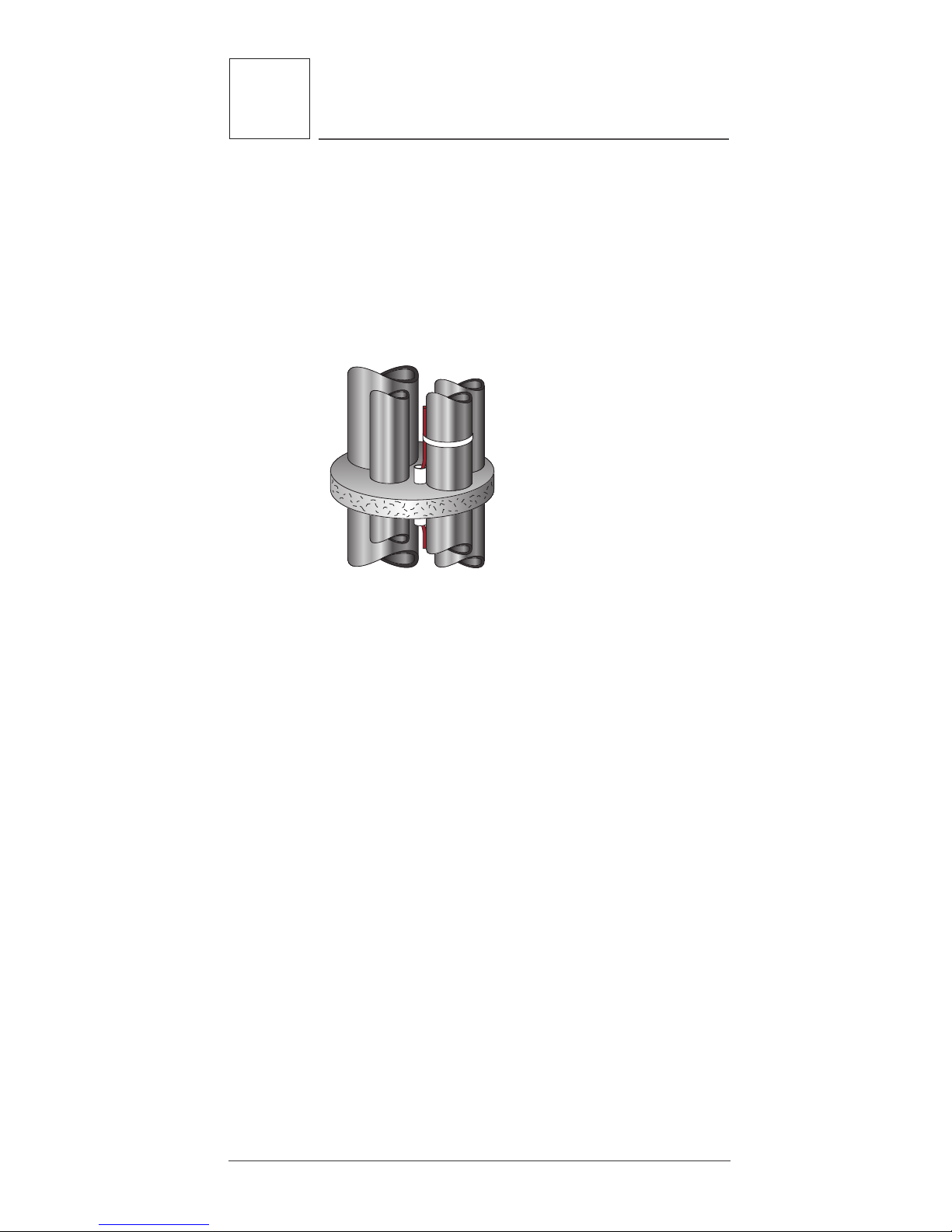
10
Raychem-IM-H58033-XLTracePipeFreezeProtectionCOM-EN 18/01
2
Installation Guidelines
• Theheatingcablemustnotbeembeddeddirectly
inthesealingmaterial;thepipeshouldhavether-
malinsulationoverit(ifallowedbylocalcodes)or
theheatingcableshouldberunthroughthepene-
trationinatubeorconduit.Iftheconduitmustbe
sealed,useapliablefire-resistantmaterial(Dow
CorningFireStop,3MFireBarrier,orT&BFlame-
Safe)thatcanberemovedifnecessary.
Figure 6: Multiple pipe floor penetration
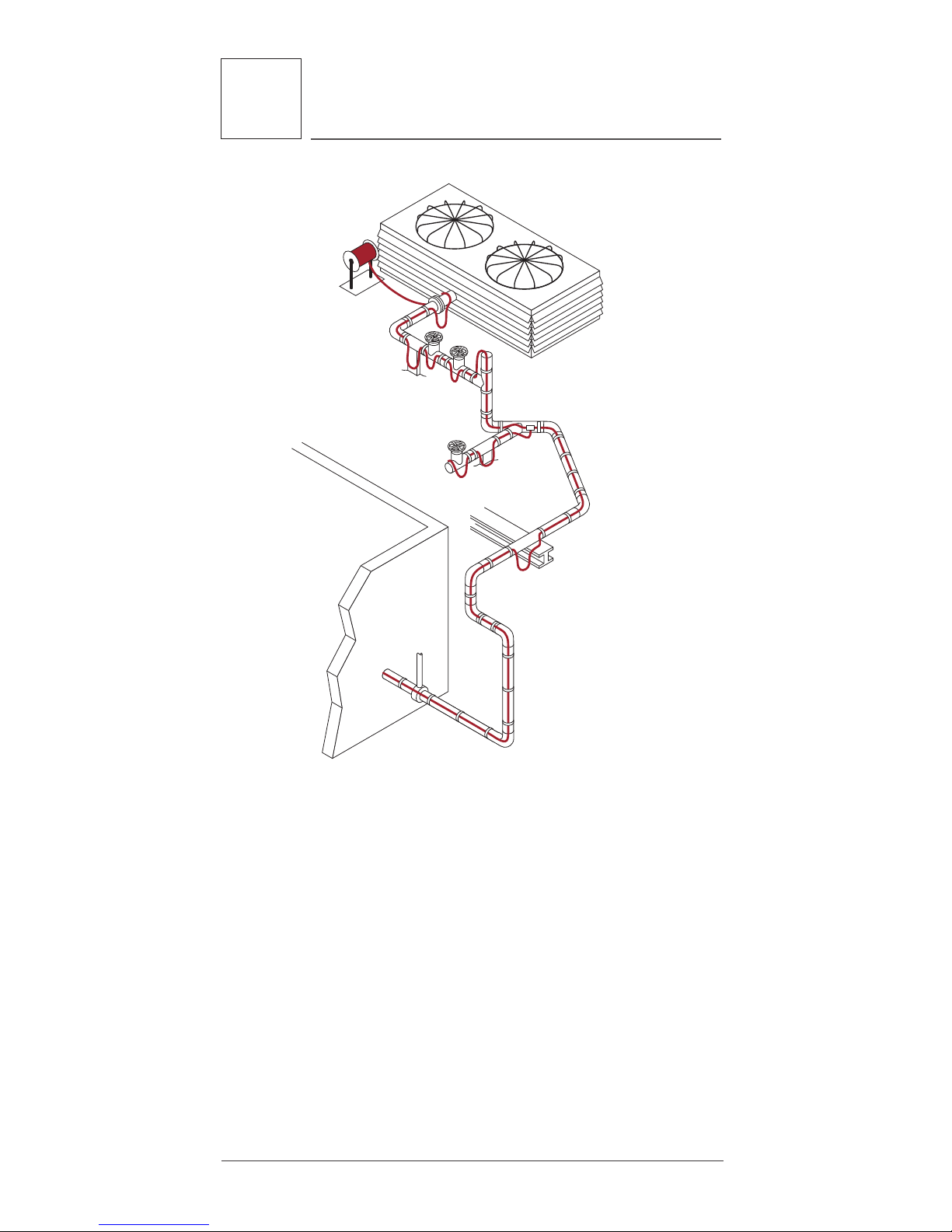
• Onverticalpipinggroups,runtheheatingcable
alongtheinsideofthepipeclosetootherpipes
soitwillnotbedamagedifthepipehitstheside
ofthefloorpenetration.Runtheheatingcable
overtheoutsideofthepipesupport.Donot
clamptheheatingcabletothepipewiththepipe
support.
• Inhigh-riseconstructionitmaybenecessaryto
installtheXL-Tracesystem10or12floorsata
timetofitintotheconstructionschedule.Ifso,
theendoftheheatingcableshouldbesealedwith
aRayClic-Eendsealandplacedinanaccessible
location.Thisallowstestingofonepartofthe
heatingcableatatime,andallowssplicingitto
anothersectionwhenthesystemiscomplete.
• WhenXL-Traceisinstalledbehindwalls,the
powerconnectionkitmustbeaccessible.
Wheneverpossible,positiontheheatingcableon
thelowersectionofthepipeasshowninFigure7to
protectitfromdamage.

11
Raychem-IM-H58033-XLTracePipeFreezeProtectionCOM-EN 18/01
2
Installation Guidelines
One heating cable
45°
Two heating cables
45° 45°
Figure 7: Positioning the heating cable
Securing the heating cable
WARNING: Damage to the heating cable can
cause electrical arcing or fire. Do not use metal
attachments such as pipe straps or tie wire. Use only
Thermal Management-approved tapes or plastic
cable ties.
Important: Before taping the heating cable to
the pipe, make sure all heat-tracing allowances for
flanges, valves, supports, and other connection kits
have been verified.
Useoneofthefollowingattachmentmethodsto
securetheheatingcableontothepipe:GT-66or
GS-54glassclothtape,AT-180aluminumtape,or
plasticcableties.
Glass clotH adHesiVe tape
• GT-66(66-footroll)general-purposetapefor
installationat40°F(4°C)andabove.Applyat
1-footintervals.
• GS-54(54-footroll)general-purposetapefor
installationbelow40°F(4°C).Applyat1-foot
intervals.
at-180
aluMinuM tape
• Requiredforplasticpipeapplicationstoensure
properpoweroutputofheatingcable.

12 Raychem-IM-H58033-XLTracePipeFreezeProtectionCOM-EN 18/01
2
Installation Guidelines
• Tapelengthwiseovertheheatingcableas
requiredbythedesigndrawingorspecification
(seeFigure8).
• Recommendedforheat-tracingpumpbodiesor
odd-shapedequipment,orascalledoutinthe
designdrawingasaheat-transferaid.
• Installattemperaturesabove32°F(0°C).
Heating cable
1 ft (0.3 m)
Pipe
Thermal insulation
Weather proofing
Glass cloth tape
AT-180 aluminum tape
over heating cable
(Required for proper
output for plastic
pipe applications)
Heating
cable
PipeAT-180
aluminum tape
Figure 8: Attaching the heating cable
ca Ble ties
• Recommendedinapplicationswherethepipesur-
facepreventspropertapeadhesion.
• Useplasticcabletiesonly.
• Cabletiesmustbehand-tightenedonlytoprevent
damagetoheatingcable!
Bending/Crossing/Cutting the Heating Cable
BendinG tH e HeatinG caBle
Whenpositioningtheheatingcableonthepipe,do
notbendtighterthan1/2"radius.Theheatingcable
doesnotbendeasilyintheflatplane.Donotforce
suchabend,astheheatingcablewillbedamaged.

13
Raychem-IM-H58033-XLTracePipeFreezeProtectionCOM-EN 18/01
2
Installation Guidelines
1/2"
Figure 9: Bending technique
crossin G tHe HeatinG caBle
XL-Traceheatingcablesareself-regulatingandmay
beoverlappedwhenevernecessarywithoutover-
heatingorburningout.
cuttinG tH e HeatinG caBle
Cuttheheatingcabletothedesiredlengthafteritis
attachedtothepipe.XL-Tracecanbecuttolength
withoutaffectingtheheatoutputperfoot.
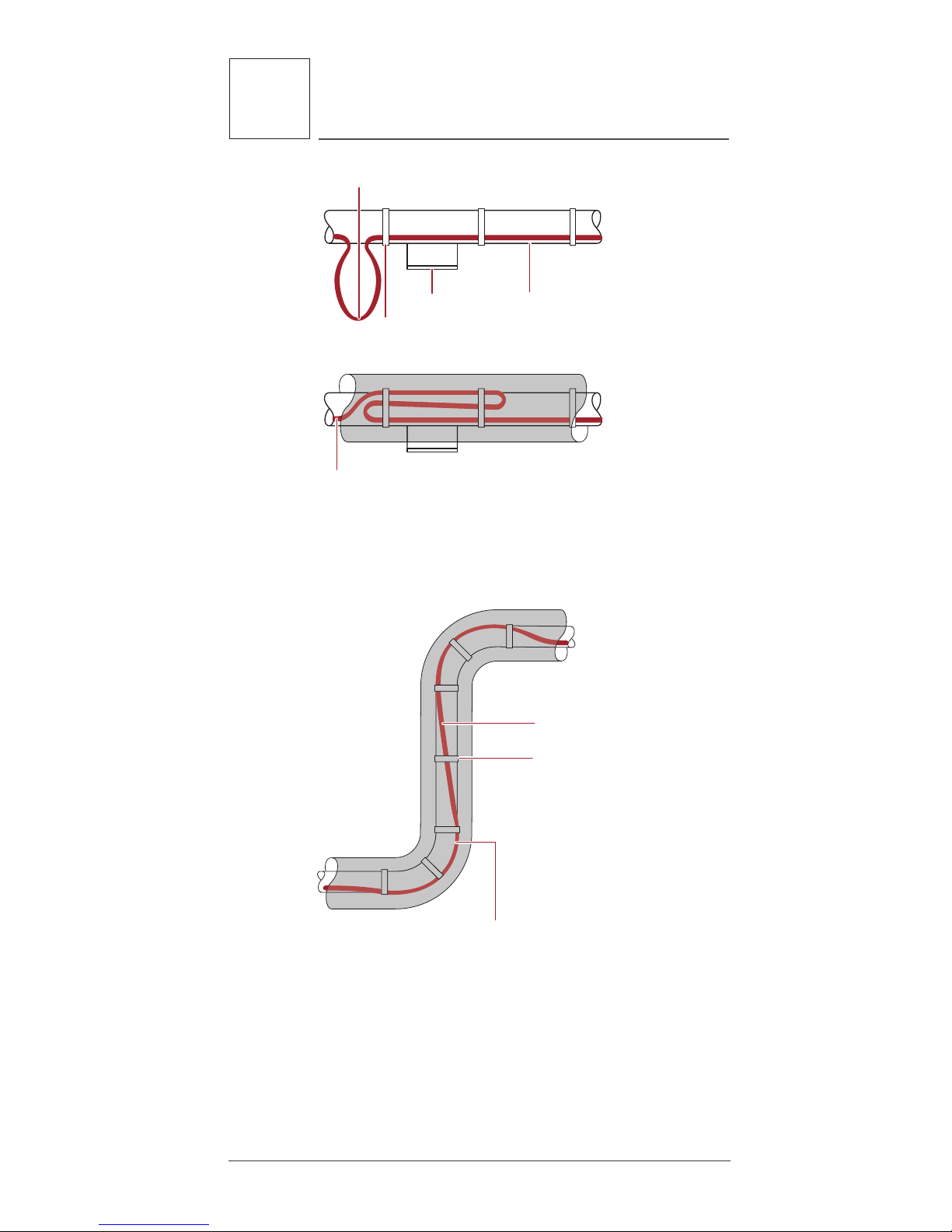
Wrapping the Heat Sinks
Oncethestraightsectionsaresecuredtheheating
cablecanbesecuredtotheheatsinks.Attachthe
heatingcabletotheheatsinksaccordingtoFigure
10below.Thelengthofheatingcableinstalledis
determinedinthedesign.

14 Raychem-IM-H58033-XLTracePipeFreezeProtectionCOM-EN 18/01
2
Installation Guidelines
Valve body
Multiple crossovers allowed
for self-regulating cables
Single crossover only, allowed
for power-limiting cables
Glass tape Pipe
Heating cable
Pipe
Heating cable
Note: Cable loop length
varies depending on
heat loss.
Figure 10: Valve
Glass tape
(typical)
Heating cable Loop length is twice
the diameter of the pipe
Figure 11: Flange

15
Raychem-IM-H58033-XLTracePipeFreezeProtectionCOM-EN 18/01
2
Installation Guidelines
Heating cable
Glass tape
Pipe
Figure 12: Pressure gauge
Glass tape
Pump discharge
Pump body
Heating cable
Pump
suction
Use AT-180
tape
Motor
To power connection
Pump body
Pump body
Figure 13: Split case centrifugal pump
16 Raychem-IM-H58033-XLTracePipeFreezeProtectionCOM-EN 18/01
2
Installation Guidelines
Heating cable secured to pipe
Glass tape
Heating cable loop
Support shoe Pipe
Figure 14: Pipe support shoe
Heating cable
Glass tape
(typical)
For pipe diameters of 2"
and larger, the heating
cable should be installed
on the outside (long)
radius of the elbow.
Figure 15: Elbow
Other manuals for XL-Trace
1
Table of contents
Other Raychem Protection Device manuals


