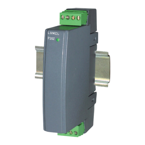
Lumel P30H User manual

1
TRANSDUCER OF DIRECT CURRENT
NETWORK PARAMETERS
P30H
USER’S MANUAL

Contents
1. Application.................................................................................................................................................3
2. Transducer set.......................................................................................................................................... 5
3. Basic requirements, operational safety.....................................................................................................5
4. Installation................................................................................................................................................. 7
4.1. Mountin ............................................................................................................................................ 7
4.2. External connection dia rams............................................................................................................8
5. Service.................................................................................................................................................... 10
5.1. Description of P30H transducer's frontal plate.................................................................................10
5.2. Power-on messa es........................................................................................................................11
5.3. Functions of the buttons..................................................................................................................12
5.3.1. Functions of sin le buttons................................................................................................................12
5.3.2. Functions of button combinations......................................................................................................14
5.3.3. Pro rammin matrix...........................................................................................................................15
5.4. Pro rammin parameters of the transducer....................................................................................16
5.4.1. Type of selected parameter value chan e.........................................................................................18
5.4.2. Chan in the floatin -point values.....................................................................................................19
5.4.3. Pro rammable parameters of the transducer....................................................................................19
5.5. Functions of the transducer.............................................................................................................33
5.5.1. Measurin input..................................................................................................................................33
5.5.1.1 Avera in time of instantaneous values...........................................................................................33
5.5.1.2 Mean values, synchronized with the clock.......................................................................................34
5.5.1.3 Maximum and minimum values displayed.......................................................................................34
5.5.1.4. Transducer configuration example for control of charging lead acid battery......................35
5.5.2. Analo outputs....................................................................................................................................38
5.5.2.1. Individual characteristic of analo outputs......................................................................................38
5.5.2.2 Analo outputs overrun support.......................................................................................................39
5.5.3 Alarm and power outputs....................................................................................................................43
5.5.4 LCD display.........................................................................................................................................44
5.5.5 Savin and readin transducer confi uration file................................................................................49
5.5.5.1 Saving transducer configuration file......................................................................................49
5.5.5.2 eading transducer configuration file...................................................................................49
5.6. Default settin s................................................................................................................................ 51
5.7. Software up rades...........................................................................................................................54
5.8. Measurin values archivin ............................................................................................................. 56
5.8.1 Transducer memory structure.............................................................................................................56
5.8.2 Internal memory..................................................................................................................................57
5.8.2.1 Structure of the record ..........................................................................................................58
5.8.2.2. Acquisition of archived data from the internal memory.......................................................59
5.8.3 Archivin confi uration........................................................................................................................61
5.8.4 Memory card or internal memory file system (optional)......................................................................62
5.8.5 Archive files structure..........................................................................................................................65
5.9. RS-485 interface.............................................................................................................................. 65
5.9.1 Connection of the serial interface........................................................................................................66
5.9.2 Description of the MODBUS protocol implementation........................................................................67
5.9.3 Description of the implemented functions...........................................................................................68
5.9.4 Interface RS-485 Master mode...........................................................................................................72
5.9.5 Interface RS-485 Monitor mode..........................................................................................................74
5.9.6 Map of the re isters.............................................................................................................................76
5.9.7 Re isters for writin and readout........................................................................................................78
5.9.8 Re isters for readout...........................................................................................................................94
5.10. Ethernet interface 10/100-BASE-T...............................................................................................104
5.10.1 Connectin 10/100-BASE-T interface.............................................................................................105
5.10.2 Web Server.....................................................................................................................................107
5.10.2.1. General view.....................................................................................................................108
5.10.2.2. Web user selection............................................................................................................108
5.10.3 FTP Server......................................................................................................................................110
5.10.3.1. FTP user selection.............................................................................................................110

P30H-09B 2 User's manual
5.10.4 Modbus TCP/IP...........................................................................................................................112
6. Accessories....................................................................................................................................... 112
6.1. Memory card.............................................................................................................................. 112
6.2. Additional resistor D5.................................................................................................................113
7. Error codes........................................................................................................................................116
8. Technical data.................................................................................................................................... 117
9. Orderin code.................................................................................................................................... 123

P30H-09B 3 User's manual
1. Application
Pro rammable transducer P30H is suited for volta e, current
(volta e measurement from a shunt) and power measurement in d.c.
circuits and for conversion of measured value into a standard d.c. and
a.c. si nal. Output si nal is alvanically insulated from input si nal and
power si nal. Transducer uses 2x8 characters LCD.
Characteristics of P30H Transducer:
●conversion of measured values into an output si nal on the base of
the individual linear characteristic,
●one or two relay alarms with the n/o contact operatin in 6 modes,
●24 VDC 30 mA auxiliary power turned on/off accordin to pro ram
(optional)
●si nalin of the set alarm values trippin ,
●pro rammin of alarm output and analo outputs reactin to the
selected input value,
●real time clock with the clock power support function in case of the
transducer power failure,
●input si nal re istration in the internal memory and SD/SDHC cards
within the pro rammed time intervals (optional),
●internal memory with 534336 record capacity,
●automatic decimal point set,
●set parameters display,
●password protection for the input parameters,

P30H-09B 4 User's manual
●compatibility with RS-485 interface with MODBUS protocol, in RTU
mode,
●measurement avera in time pro rammin ,
●SD/SDHC card use – FAT and FAT32 system compatibility,
●Master RS-485 mode – 1 device query,
●Ethernet interface10/100 BASE-T (optional)
◦protocol: Modbus TCP/IP, HTTP, FTP,
◦services: web server, FTP server, DHCP client
The values measured and calculated by the transducer:
volta e+ rescalin constant
current (as measured volta e at the shunt ± 150 mV) + rescalin
constant
power
volta e difference in time 5 s, 30 s, 1 min, 5 min, 15 min (dU)
current difference in time 5 s, 30 s, 1 m, 5 m, 15 m (dI)
avera ed volta e (e .15 min.)
avera ed current (e .15 min.)
avera ed power (e .15 min.)
time in seconds
time in hours and minutes
char e capacity in Ah
imported ener y
exported ener y
maximum and minimum values.
Transducer allows for the use of volta e and current rescalin
constants, which will be included in the measurement and calculation
of all measurement values. Value up rade time does not exceed 1
second. All values and confi uration parameters are available throu h
RS-485 and Ethernet (Modbus protocol) (option).

P30H-09B 5 User's manual
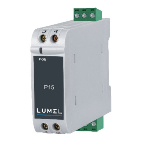
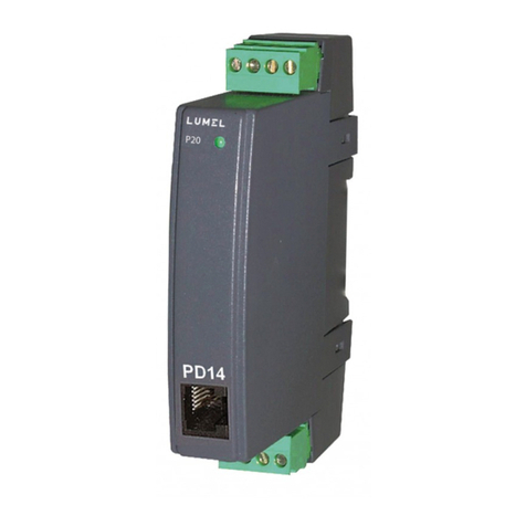
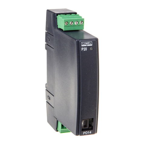
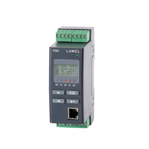
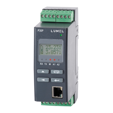
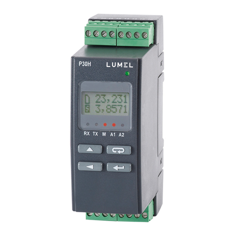
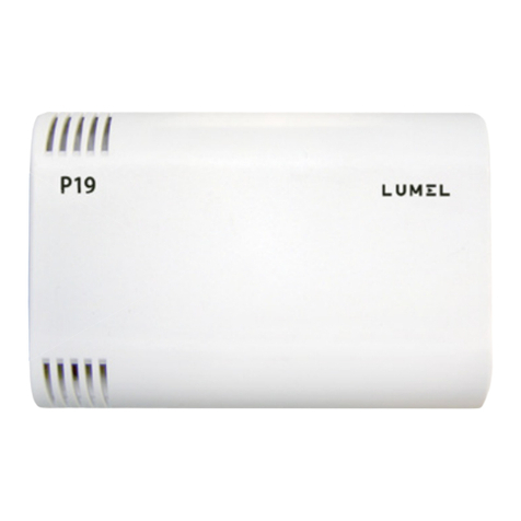
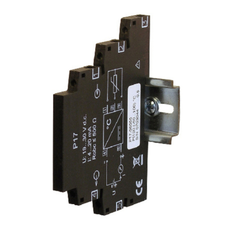
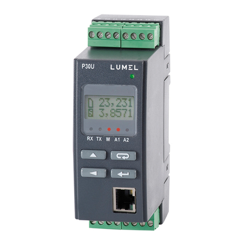
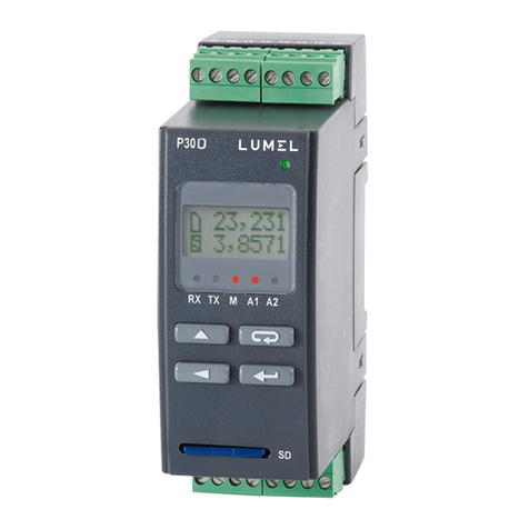
Fig. 1 Appearance of P30H transducer different versions.
2. Transducer set
●P30H Transducer 1 pc
●user's manual 1 pc
●warranty card 1 pc
●plu with the screw terminals 2 pc
3. Basic requirements, operational safety
In the security scope, the transducer meets the requirements of the EN
61010-1 standard.
Comments concerning safety
●Assembly and installation of the electrical connections should
conducted only by people authorised to perform assembly of electric
devices.

P30H-09B 6 User's manual
●Always check the connections before turnin the transducer on.
●The transducer is desi ned to installation and usa e in the industrial
electroma netic environment.
●A switch or a circuit-breaker should be installed in the buildin or
facility. It should be located near the device, easily accessible by the
operator, and suitably marked.
●Removal of the transducer housin durin the warranty period voids
the warranty.

P30H-09B 7 User's manual
4. Installation
4.1. Mounting
The P30 transducer are desi ned for installation on a 35 mm rail
acc. to EN 60715. Overall dimensions and mountin is shown in Fi ure 2.
Fig.2 Overall dimensions and mounting of the transducer.
The output si nals are alvanically isolated from the input si nals and
power supply.
The meter housin is made of plastic. On the outside two clampin
strips that can accommodate cables up to 2.5 mm2 in diameter.

P30H-09B 8 User's manual
4.2. E ternal connection diagrams

P30H-09B 9 User's manual
Note!
If you need to measure voltages higher than 300 d.c., must use an external additional
resistor type D5 / 1 (600 ) or D5 / 2 (1000 )
For the measured voltage range 300...600
P30H set with additional resistor D5 meets the
requirements:
- CAT III,
- basic isolation between input circuits (terminals
1-4) and other circuits ( 60s /3,51k a.c. )
For the measured voltage range
600...1000 P30H set with additional resistor D5
meets the requirements:
- CAT III,
- basic isolation between input circuits (terminals
1-4) and other circuits ( 60s /3,51k a.c. )
Fig.3 Wiring diagram of the P30H
transducer

P30H-09B 10 User's manual
5. Service
5.1. Description of P30H transducer's frontal plate
Fig.4 Description of the transducer's frontal plate
Note: Memory card (optional) should be inserted into the transducer
with contacts on the bottom side.
Description of LED indicator:
RX – reen LED - indicator of data receivin on RS-485 link
TX – yellow LED - indicator of data transmission on RS-485 link
M – red LED – indicates reachin the limit of the internal archive
memory and savin the data on the SD/SDHC card - when the internal
memory is 95% full, LED in constantly on, if the transducer is usin a
memory card, LED is pulsatin durin the savin process until it is
finished.

P30H-09B 11 User's manual
A1 – red LED – indicates en a in the first alarm
A2 – red LED – indicates en a in the second alarm or 24VDC
power.
Power indicator – reen LED
5.2. Power-on messages
After connectin the external si nals and turnin the power on
accompanied by turnin the reen LED (power indicator) on, transducer
displays the type, current software version and the serial number. If the
transducer is equipped with Ethernet interface (P30H-XX2XXXXXXX),
then after displayin the serial no., the device displays also the IP
address saved in memory or received from DHCP server.
Fig.5 Starting messages of the transducer not equipped with
Ethernet interface
Fig.6 Starting messages of the transducer equipped with
Ethernet interface
The transducer automatically switches to the operatin mode of

P30H-09B 12 User's manual
measurement and processin the analo output si nal after approx. 3
seconds. Measured value is displayed in the upper line of the display,
the additional information is displayed in the lower line, see 5.5.4).
LED display shows the RS-485 transmission status, internal memory
usa e and alarm status. Ethernet services (WWW server, FTP server,
Modbus TCP/IP) are started for transducers equipped with Ethernet
interface.
5.3. Functions of the buttons
5.3.1. Functions of single buttons
- confirm button
●enterin the pro rammin mode (hold the button for at least 3
seconds),
●menu item selection – level selection,
●enterin the parameter value chan e mode,
●acceptin the altered parameter value,
●chan e of content displayed on the bottom line of the display
●turnin the transducer on and holdin down the button - enterin into
software update mode via RS-485 interface, the link parameters: baud
rate 9600 bit/s, 8N2 mode.
- increase value button
●chan e of the displayed value,
●navi ation within selected level,
●chan e of the selected parameter value – value increase,

P30H-09B 13 User's manual
- di it chan e button
●chan e of the displayed value
●movin to the parameter roup level,
●navi ation within selected level
●selected parameter value chan e – movin to subsequent number
●turnin the transducer on and holdin down the button - enterin into
software update mode via RS-485 interface, the link parameters: baud
rate 115200 bit/s, 8N2 mode.
- cancel button
●enters the transducer parameter display mode (hold the button for at
least 3 seconds),
●quits the transducer parameter display menu
●chan e of content displayed on the bottom line of the display
●cancels the parameter chan e
●forced exit from the pro rammin mode (hold the button for at least 3
seconds),
●turns the transducer with the button pressed – forces loadin
transducer confi uration from the P30H_PAR.CON file saved to the
external SD/SDHC card or internal file system memory (depends on the
version).

P30H-09B 14 User's manual
5.3.2. Functions of button combinations
- holdin down for approx. 3 second
●deletes alarm si nalization; this operation works only with support
function turned on;
- holdin down for approx. 1 second
● displays maximum of the currently displayed value
- holdin down for approx. 1 second
● displays minimum of the currently displayed value
- holdin down for approx. 1 second
●unmounts the SD/SDHC card allowin it to be safely removed – for
the transducers with external SD/SDHC card slot
- holdin down for approx. 1 second
●forces the rewritin of the archive from internal memory to the
SD/SDHC card – for the transducers with external SD/SDHC card slot
●overrides the rewritin of the archive from internal memory to file
system memory – for the transducers with Ethernet interface; this
operation allows for the loadin the files with current archive data from
transducer via FTP protocol
- holdin down for approx. 3 seconds, deletin extremal
values

P30H-09B 15 User's manual
Pressin and holdin the button for approx. 3 seconds causes
exitin to the pro rammin matrix. The pro rammin matrix can be
protected by an access code.
5.3.3. Programming matri
Fig. 7 P30H Transducer service algorithm

P30H-09B 16 User's manual
5.4. Programming parameters of the transducer
Pressin the button Pressin and holdin down the button
for approx. 3 seconds allows to exit to the pro rammin matrix. If the
output is password-protected, a password entry messa e will be
displayed. If the entered password is incorrect, a followin messa e
appears: Invalid Code. Enterin a valid password starts
pro rammin matrix. The Fi . 8. shows the transition matrix in the
pro rammin mode. Buttons allow the selection of the menu level and
movin throu h the sublevel parameters or . Parameter
symbol is displayed in the upper display line, the parameter itself is
displayed in the lower line. To edit a iven parameter, press the
followin button: . To cancel the parameter chan e, press the
followin button: . To exit the pro rammin matrix and enter the
measurement mode, press and hold the followin button: . If the
transducer is left in the parameter pro rammin mode, after 30 seconds
it will exit pro rammin mode and start to display the displayed value.
Settings
Input
Parameter
s of the
main input
VoltRang
ran e of
volta e
measurem
ent 12 /
48 / 100 /
250 V
DemandTm
method of
avera in
the mean
values P, I,
U
Averag.
Avera in
time of
instantaneo
us values
I direct
Pro ram
possibility
to reverse
the current
direction
Clear En
Clear
ener y
counter
Reset AV
Restart
countin
the
avera e
values
TempMeas
The
choice of
how to
obtain
temperatu
re values
Rst.Coun
Timer reset
Syn.Time
Selection of
timer
synchroniza
tion
DeltTime
Selectin
the time to
indicate the
delta
volta es
and
currents
CurrThrs
Current
threshold
above
which time
is counted
Primar.
Input
volta e
(included
when
calculatin
the
rescalin
ratio)
Second.
Output
volta e
(included
when
calculatin
the
rescalin
ratio)
Shunt I
Shunt
nominal
current
Shunt mV
The
volta e
correspon
din to the
nominal
current
shunt

P30H-09B 17 User's manual
Settings
Display
Display
parameters
DecimalP
Minimum
decimal
point
Bcklight
Time of a
display panel
illumination
Bckl.Int
Intensity of
LCD display
panel
illumination
Settings
Alarm 1
Alarm 1
parameter
s
Param.A1
Input value
type for
alarm 1
Type A1
Alarm type
1
OverLoA1
Alarm 1
lower limit
OverHiA1
Alarm 1
upper limit
DlyOnA1
Alarm 1
activation
delay
DlyOffA1
Alarm 1
deactivati
on delay
OnLockA1
Alarm 1
re-
activation
delay
SgKeepA1
Alarm 1
si nalizatio
n latch
Settings
Alarm 2
Alarm 2
parameter
s
Param.A2
Input value
type for
alarm 1
Type A2
Alarm type
2
OverLoA2
Alarm 2
lower limit
OverHiA2
Alarm 2
upper limit
DlyOnA2
Alarm 2
activation
delay
DlyOffA2
Alarm 2
deactivati
on delay
OnLockA2
Alarm 2
re-
activation
delay
SgKeepA2
Alarm 2
si nalizatio
n latch
Settings
Output
Output
parameter
s (analo
output #2
parameter
s
available
only when
the
transducer
is
equipped
with an
additional
output)
ParamAn1
Control
value of
analo
output 1
type
AnIn Lo1
Input 1
lower limit
AnIn Hi1
Input 1
upper limit
AnOutLo1
Output 1
lower limit
AnOutHi1
Output 1
upper limit
OverSer1
Enablin
an
overrun of
output 1
Parameters available only when the OverSer1 option is on
OvOutLo1
Output 1
lower limit
overrun
OvOutHi1
Output 1
upper limit
overrun
OvrOutL1
Output 1
expected
value when
the lower
limit is
exceeded
OvrOutH1
Output 1
expected
value when
the upper
limit is
exceeded
ParamAn2
Control
value of
analo
output 2
type
AnIn Lo2
Input 2
lower limit
AnIn Hi2
Input 2
upper limit
AnOutLo2
Output 2
lower limit
AnOutHi2
Output 2
upper limit
OverSer2
Enablin
an
overrun of
output 2
Parameters available only when the OverSer2
option is on
OvOutLo2
Output 2
lower limit
overrun
OvOutHi2
Output 2
upper limit
overrun
OvrOutL2
Output 2
expected
value when
the lower
limit is
exceeded
OvrOutH2
Output 2
expected
value when
the upper
limit is
exceeded
Settings
Mbus 485
RS-485
interface
parameter
s
Address
Device
address
Mode nit
Frame type
BaudRate
Baud rate
Base.Reg
Base
re ister
number
(Master
mode)
No.ofVal
Number of
the
queried
values
(Master
mode)
ValType
Type of
the
queried
values
(Master
mode)
Interv.
Query
period
(Master
mode)
AnswTime
Max.
response
time (Master
mode)
Mode
Interface
RS-485
operatin
mode
Mast.Fun
Selection of
the
function
type for the
interface
operation in
Master
mode
No.OfErr
Allowed
number of
the failed
queries for
RS-485
Master
mode
Settings
Archive
Archivin
parameter
s
Arch.Val
Archived
values
selection
Param.Ar
Value type
tri erinin
conditional
archivin
Ar. Mode
Archivin
type
OverLoAr
Archivin
lower limit
OverHiAr
Archivin
upper limit
Ar. Time
Archivin
period
Ar.Erase
Deletin
an internal
archive
Rec.ToSD
Override
allowin for
copyin of
the internal
archive to
SD/SDHC
card
Param.SD
The
percenta e
of the
internal
archive
space used
which
tri ers
automatic
writin on
SD/SDHC
card

P30H-09B 18 User's manual
Settings
Ethernet
Ethernet
interface
parameter
s
DHCP
Enable/dis
able DHCP
client
addrIP32
B3,B2 byte
of IP
address
(IPv4)
addrIP10
B1,B0 byte
of IP
address
(IPv4)
mask 32
B3,B2 byte
of the
subnet
mask
mask 10
B1,B0
byte of the
subnet
mask
gate 32
B3,B2
byte of the
default
ateway
address
gate 10
B1,B0
byte of the
default
ateway
address
MAC 54
B5,B4 byte
of the
transducer
MAC
address
MAC 32
B3,B2 byte
of the
transducer
MAC
address
MAC 10
B1,B0 byte
of the
transducer
MAC
address
acquired from DHCP or entered manually when DHCP is off, format:
B3.B2.B1.B0
format : B5:B4:B3:B2:B1:B0
AddrmTCP
Device
address for
Modbus
TCP/IP
service
PortMbus
Modbus
TCP/IP
port
TimeMbus
Port
closin
time of
Modbus
TCP/IP
service port
if idle [s]
no.c.TCP
The number
of allowed
simultaneou
s
connections
to Modbus
TCP/IP
service
p.comFTP
FTP
server
data port
port FTP
FTP
server
command
port
portHTTP
Web
server port
number
10/100Mb
Baud rate
EthStdPa
Settin the
new
parameters
of Ethernet
interface
ReInitEt
Executin
the
chan es in
the
Ethernet
interface
parameters
Settings
Service
service
parameter
s
Fabr.Par
Enter
standard
parameter
s.
Security
Enter a
password
Time
Settin the
current
time
Date
Settin the
current date
AutoTime
Automatic
DST and
inversely
DispTest
LCD
display
and LED
indicators
test
Language
Menu
lan ua e
selection
SaveFile
Override
allowin for
savin the
confi uratio
n file to
SD/SDHC
card
Separat.
Decimal
separator
character in
the file
archive
Fig. 8 Programming matrix
5.4.1. Type of selected parameter value change
To increase the value of selected parameter, press the followin
button: . Pressin the button once increases the value by 1.
Increasin the value by one when 9 is displayed, chan es this number
to 0. Number is chan ed after the followin button is pressed: .
Pressin the button durin the most important number allows to
chan e the number si n after the followin button is pressed: .
To accept the set parameter, press the followin button: .
The parameter will be saved. Pressin the followin button: while
chan in the parameter value will cancel the writin .

P30H-09B 19 User's manual
5.4.2. Changing the floating-point values
The chan e is done in 3 sta es (to move to a next sta e press
the followin button: ).
●settin the decimal point (00000., 0000.0, 000.00, 00.000, 0.0000);
button moves the point to the left, while button moves point
to the ri ht. Pressin the followin button: while chan in the
parameter value will cancel the writin .
●settin the value from -99999…99999 ran es for the normal values;
●settin the order of ma nitude x1, x103, x106, x109 (symbols „k”, „M”
and „G” for orders of 103, 106, 109 respectively are displayed)
5.4.3. Programmable parameters of the transducer
The followin table shows the pro rammable parameters and the ran e
of their values.
Table 1
Settings
Input
Parameter
symbol
Description Ran e of chan es
VoltRang Selection of ran e of
volta e measurement
12 V Input ran e 12 V
48 V Input ran e 48 V
100 V Input ran e 100 V
250 V Input ran e 250 V
DemandTm Synchronization of
volta e, current and
avera e power
Mov.Wind 15-minute movin window,
value not synchronized
with the clock
15 min The measurement
synchronized with the
clock, the time
a re ation 15 minutes
30 min The measurement
Other manuals for P30H
1
Table of contents
Other Lumel Transducer manuals