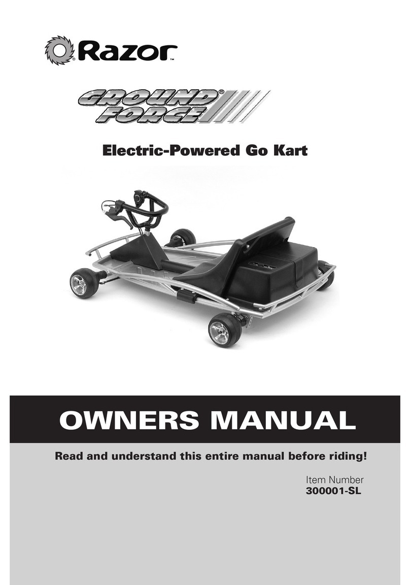
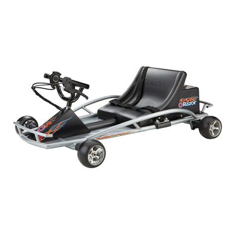
Razor Ground Force User manual

Owner’s Manual
TM TM
Electric-Powered Go Kart
Read and understand this entire manual before driving.
(
Specifications subject to change without notice.)
Save this manual with your original sales receipt.
For service bulletins and answers to frequently asked questions, go to: www.razor.com.
For your records, write serial number (located on motor bracket)__________________
Item number: 300001-SL
TM

2
NOTE: This manual contains many “Warnings” and “Cautions” concerning the
consequences of failing to maintain, inspect or properly use your Ground Force. Because
any incident can result in serious injury or even death, we do not repeat the warning of
possible serious injury or death each time such a warning is mentioned.
AN IMPORTANT MESSAGE TO RIDERS AND PARENTS: READ THIS ENTIRE MANUAL
BEFORE OPERATING OR ALLOWING USE OF THE Ground Force, AND KEEP THIS MANUAL
AVAILABLE FOR FUTURE REFERENCE.This manual contains important safety information. For
safety, it is your responsibility to review this information and make sure that all riders understand
all warnings, cautions, instructions and safety topics and assure that young riders are capable
and able to safely and responsibly use this product. Razor USA recommends that you
periodically review and reinforce the information in this manual with younger riders, and you are
required to inspect and maintain your child’s vehicle to insure their safety.
The recommended rider age is only an estimate, and can always be effected based upon a
particular rider’s size, weight or skills. If the rider is unable to fit comfortably on the Ground Force,
don’t attempt to ride it.
Keep this product away from small children and always understand that this product is intended
for use only by persons who are, at a minimum, completely comfortable and competent while
operating the vehicle.
Table of Contents
1. Important Information . . . . . . . . . . . . . . . . . . . . . .2
2. Key Parts of the Ground Force . . . . . . . . . . . . . . . .4
3. Preparing for First-Time Use
3A.Un-box . . . . . . . . . . . . . . . . . . . . . . . . . . . . . .5
3B. Steering wheel . . . . . . . . . . . . . . . . . . . . . . . .5
3C. Attach the seat . . . . . . . . . . . . . . . . . . . . . . . .6
3D. Attach the seat with the seat chain . . . . . . . . .7
3E. The brake . . . . . . . . . . . . . . . . . . . . . . . . . . . .7
3F. Charging prior to use . . . . . . . . . . . . . . . . . . . .8
3G. Circuit breaker . . . . . . . . . . . . . . . . . . . . . . . . 9
4. Safety Check Before Riding . . . . . . . . . . . . . . . . .9
5. Maintenance and Repairs . . . . . . . . . . . . . . . . . . .9
6. Safety . . . . . . . . . . . . . . . . . . . . . . . . . . . . . . . .14
7. Illustrated Parts Breakdown . . . . . . . . . . . . . . . . .16
8. Limited Warranty and Owner Registration . . . . . . .18

3
GENERAL WARNING: Driving the Ground Force can be a hazardous activity. Electric
vehicles can, and are intended to, move and it is therefore possible to get into dangerous
situations and/or lose control and/or fall off. If such things occur you can be seriously injured or
die. LIKE ANY OTHER MOVING PRODUCT,USING THE GROUND FORCE CAN BE A
DANGEROUS ACTIVITY AND MAY RESULT IN INJURY OR DEATH EVEN WHEN USED WITH
SAFETY EQUIPMENT AND OTHER PRECAUTIONS. USE AT YOUR OWN RISK AND USE
COMMON SENSE.
• Always check and obey any local laws or regulations which may affect the locations where the
Ground Force may be used on public property. The Ground Force is meant to be used only in
controlled environments free of potential traffic hazards, and not on public streets or sidewalks.
Do not try to ride your Ground Force on public streets or in any areas where pedestrian or
vehicle traffic may present a risk of collision or injury to yourself or others. Watch out for potential
obstacles including pedestrians, skaters, skateboards, scooters, bikes, children or animals who
may enter your path, and respect the rights and property of others.
• Do not ride the Ground Force in wet weather and never immerse the Ground Force in water, as
the electrical and drive components of the Ground Force could be damaged by water or create
other possibly unsafe conditions.
• The Ground Force is designed to perform best outdoors on solid flat, clean and dry surfaces.
Wet, slick or uneven and rough surfaces may impair traction and contribute to possible accidents.
Use only on flat, dry, level ground without loose debris, such as rocks or gravel. Do not drive the
Ground Force in mud, ice, puddles or water. Avoid excessive speeds that can be associated with
downhill rides. Never risk damaging indoor surfaces such as carpet or flooring by use of a
Ground Force indoors.
• Do not ride at night or in impaired visibility conditions.
• Always wear proper protective equipment, such as an approved safety helmet, elbow pads and
kneepads. A helmet may be legally required by local law or regulation in your area, and should
always be worn when driving a Ground Force. Always wear shoes, never drive barefooted or in
sandals, and keep shoelaces tied and out of the way of the wheels, motor and drive system.
• The electric motor in your Ground Force can become hot when in use. Do not touch the motor
and handle the Ground Force carefully.
• Do not exceed the weight limit of 120 pounds (see warning on back page).
• Do not attempt or do stunts or tricks on your Ground Force. The Ground Force is not made to
withstand abuse from misuse such as jumping, curb grinding or any other type of stunts.
• The charger supplied with the Ground force should be regularly examined for damage to the
cord, plug, enclosure, and other parts and in the event of such damage, the kart must be not
charged until it has been repaired or replaced.
• Use only with the recommended charger.
• The charger is not a toy.
• If wiping down and cleaning your Ground Force with liquid, always disconnect from the charger
before cleaning.
• Refer to the chapter on Safety for additional warnings.
FAILURE TO USE COMMON SENSE AND HEED THE ABOVE WARNINGS FURTHER
INCREASES RISK OF SERIOUS INJURY. USE AT YOUR OWN RISK AND WITH APPROPRIATE
AND SERIOUS ATTENTION TO SAFE OPERATION. USE CAUTION.

4
WARNING: REGARDING USE OF NON-RAZOR PRODUCTS WITH YOUR
RAZOR Ground Force. The Ground Force has been built to certain Razor design
specifications. The original equipment supplied at the time of sale were selected on
the basis of their compatibility with the frame, fork and all other parts. Certain after-
market products may or may not be compatible. Consult your retailer or call Razor
prior to modifying or replacing any component with a non-factory specified product.
WARNING: CHECK LOCAL LAWS REGARDING USE. Check local laws and
Brake lever
brake adjuster (auxiliary)
Chain adjuster
Speed control
Steering wheel
Tread Wheel
NOTE: Do not
activate the speed
control on the
steering wheel
unless you are in a
safe, outdoor
environment. Use
this product only in
areas free of
potential traffic
hazards and not on
public streets or
sidewalks.
2. Key parts of the Ground Force
Charger port
Tie-rod

5
regulations to see where and how you may use your Razor Ground Force legally.
In many states and local areas, riders are required BY LAW to wear a helmet.
Check local laws and regulations regarding laws governing helmet use, age and
vehicle operation in your area.
The transformer/charger supplied with the electric scooter should be regularly
examined for damage to the cord, plug, enclosure and other parts, and, in the
event of such damage, the scooter must not be charged until it has been repaired
or replaced.
Use ONLY with the recommended charger. The charger is not a toy. If cleaning
your electric scooter with liquid, always disconnect from the charger before
cleaning.
Battery Care and Disposal
WARNING: If a battery leak develops, avoid contact with the leaking acid and
place the damaged battery in a plastic bag. Refer to the following disposal
instructions.
If acid comes into contact with skin or eyes, flush with cool water for at least 15
minutes and contact a physician.
Do not store the battery in temperatures above 75° or below -10° F.
DISPOSAL: Your Razor product uses sealed lead-acid batteries. They must be
recycled or disposed of in an environmentally sound manner.
Do not disposed of a lead-acid battery in a fire. The battery may explode or leak.
Do not dispose of a lead-acid battery in your regular household trash. The
incineration, landfilling or mixing of sealed lead-acid batteries with household trash
is prohibited by law in most areas.
Return exhausted batteries to a federal or state approved lead-acid battery recycler
or a local seller of automotive batteries. If you live in the State of Florida or
Minnesota, it is prohibited by law for anyone to throw away lead-acid batteries in
the municipal waste stream.

6
WARNING: Failing to properly adjust and tighten the screws, nuts and bolts that affix
the steering wheel and seat can cause you to lose control and crash.
Estimated assembly and adjustment time: allow up to 45 minutes, not including
initial charge time. Allow up to 8 hours for initial charge (see page 8 and 9 for
charging information)
3. Preparing for First-Time Use
3A. Un-box. Remove contents from box. Remove the foam separators that protect the
various components from damage during shipping. Inspect the contents of the box for
scratches in the paint, dents or kinked cables that may have occurred during shipping.
The Ground Force was 95 percent assembled and packed at the factory to prevent
shipping damage and there should not be any problems, even if the box has a few scars
or dents. But if there are, contact Razor USA, toll free, at (866) 467-2967 to resolve any
problems.
3B. Steering wheel. Remove the bolt and washers at the end of the steering axle as
shown in Figure 2a. Untangle the wires and orient as shown in Figure2b. Insert steering
axle into steering column as shown in Figures 2b and 2c.
Carefully turn the Ground Force on it’s side. We recommended that you have someone
hold the Ground Force up or, alternately, you can lean it against a wall for the installation
of the tie-rod to the steering axle.
WARNING: Flipping the Ground Force upside down is not recommended as it could
damage the control wires from the steering wheel.
• 5mm hex key wrenches.
• 10mm box wrench (spanner)
• Razor recommends assembly by an adult with experience in mechanics. Some tools may be
supplied, however we recommend the use of mechanic’s grade tools. Use the supplied tools only
as a last resort.
TOOLS REQUIRED FOR ASSEMBLY

7
Figures 2a, 2b and 2c.
Positioning the steering wheel for attachment to tie-rods.
Tighten securely. Position the tie-rod control arm onto the steering axle as shown in
Figure 3a and install the washers and fixing bolt. Using a 10mm wrench, tighten securely.
Figure 3a and 3b. Tighten the tie-rod control arm using a 5mm hex key wrench.
WARNING: Failure to use the washer and lock washer or failure to properly tighten
the steering wheel may cause you to lose control and crash.
3C. Attach the seat without seat belt assembly. Locate the four (4) long seat
attachment screw and spacer washers in the parts bag. Position the seat over the frame
and align it with the holes in the frame. Insert the screws as shown in Figure 4a, using the
spacer washer as indicated by the arrow in Figure 4a. Insert all four screws and washers
and tighten securely using two Allen key wrenches as shown in Figure 4b.

8
Figure 4a and 4b.
3D. Optional attaching the seat with seat belt assembly. Locate the four (4) long seat
attachment screws and seat-belt assembly in the parts bag. Position the seat over the
frame and align it with the holes in the frame. Position the seat-belt anchors with the
lap/shoulder assembly on the left side and the receiver latch on right side. Insert the
screws as shown in Figure 5a and tighten. Install the shoulder belt anchor to the back of
the seat as shown in Figure 5b using the supplied screw, tighten securely.
Figure 5a and 5b.
WARNING: The seat belt arrangement suppled with the Ground Force is for “play”
use only. It is not an ASTM-approved safety belt system and is not intended to function as
an approved lap/shoulder/seat restraining device. The seat belt system is not required for
normal use. Install and use at your own risk.

9
NOTE: Although we make every effort to keep our manual up-to-date, if your Ground
Force does not look exactly as shown here, then we may have made improvements since
this document was printed. Check out the Razor website: www.razor.com for technical
updates on the latest service and adjustment procedures.
3E. The brake. The Ground Force is fitted with a hand-operated brake. To use the brake,
squeeze the brake lever to increase the pressure on the brake until so you come to a
smooth and controlled stop. The brake lever is fitted with a cable adjuster to compensate
for cable stretch and/or to fine tune the lever movement to brake engagement. To adjust
the play, thread the adjuster in or out (arrows, Figure 6a) 1/4 to 1/2 turn until the desired
brake adjustment is attained.
If the adjuster at the lever is threaded outward and the brake still has too much slack, use
the auxiliary adjuster at the rear brake for additional adjustment (shown in Figure 6b).
When properly adjusted, the brake lever will have approximately 3mm of free play before
the brake engages
Figures 6a Figure 6b.
WARNING: Practice in an open area free from obstacles until you are familiar with the
brake function. Avoid skidding to a stop as this can cause you to lose control as well as
cause damage the rear tires. DO NOT RUN OVER ANY OBJECT AS IT COULD
DAMAGE THE BRAKE OR DRIVETRAIN.
3F. Charging the battery prior to use. Your Ground Force may not have a fully charged
battery at the time of purchase. Therefore it is a good idea to charge the battery prior to
use. The charging input, on/off switch and overload breaker are located on top of the
battery/motor cover.

10
Plug in the charger as shown in Figure 7a and connect to a household wall outlet.
Figure 7a Figure 7b.
The charger has a small window with a LED to indicate the charge status (Figure 7b).
Refer to the illustration on the charger unit for the actual “charging” and “charged” status
indications for your model charger.
The initial charge may take from a few minutes to up to 4 hours or more depending on
the level of depletion.
If your charger does not look exactly like the one in Figure 7b, your unit has been
supplied with an alternative charger. The specifications and charging procedure would not
change, however.
NOTE: The initial charge could take up to 8 hours. Be sure to fully charge prior to
using your Ground Force for the first time.
3G. Circuit breaker. The circuit breaker (next to charger input port in Figure 7a) will
automatically shut off the power to the motor in the event an overload condition is placed
on the motor. An excessive overload, such as too heavy a driver or too steep a hill, could
cause the motor to overheat. If the Ground Force suddenly stops running, wait a few
seconds and then push the breaker to reset the circuit. Avoid whatever conditions caused
the breaker to trip and avoid repeatedly tripping the breaker.

11
4. Safety Check Before Driving
4A. Loose parts. There should not be any unusual rattles or sounds from loose parts or
broken components. If you are not sure, ask an experienced mechanic to check.
4B. Brake. Check the brake for proper function. When you squeeze the lever, the brake
should provide positive braking action.
4C. Frame and steering wheel. Check for cracks or broken connections. Although
broken frames are rare, it is possible for an aggressive driver to bash into a curb or wall
and wreck and bend or break a frame. Get in the habit of inspecting yours regularly.
CAUTION: This product moves when used. Exercise caution and common sense at
all times. DO NOT RUN OVER ANY OBJECT AS IT COULD DAMAGE THE BRAKE OR
DRIVETRAIN.
5. Maintenance and Repairs
NOTE: Tires and drive system are subject to normal wear and tear. It is the
responsibility of the user to periodically inspect the tires for excess wear and adjust and
replace drive train components as required.
Check out the Razor website: www.razor.com for any updates on the latest maintenance,
repair and trouble-shooting procedures.
5A. Adjusting the DRIVE CHAIN
NOTE: Turn power switch off before maintenance procedures.
WARNING: To avoid a pinch or injury, keep fingers away from moving sprockets and
chain.
If the drive system makes loud noises, slips or makes grinding sounds during the power-
on condition, this indicates the drive chain is probably making the noise. This can be
caused by the chain being adjusted too tight during assembly or coming loose from
normal wear-and-tear.
NOTE About chain adjustment: The chain should be not be under tension nor
floppy loose. There should be about 3/8-inch (10mm) of slack (refer to figure 8c). BE
CAREFUL NOT TO ADJUST TOO TIGHT. The tensioning system can easily impart too
much tension and snap the chain or bend the motor output shaft. Turn the adjusting bolt
by hand 1/8 to 1/4 turn or less, at a time and recheck the adjustment each time.

12
If the chain is too tight, or too loose (skips or comes off), then it may need to be
readjusted. To adjust the chain:
5A1. Referring to Figure 8a, loosen the chain jack-screw locknut (B) and tighten or loosen
the adjusting bolt (A) to tighten or loosen the chain as needed.
Referring to Figure 8b, the chain-drive system consists of the drive-shaft sprocket (A), the
roller chain (B), the adjusting bolt (C and B in 8a), and the motor shaft sprocket (D).
Figure 8a Figure 8b Figure 8c
NOTE: the motor cover does not need to be removed for this adjustment procedure.
The chain adjustment can be checked tipping the Ground Force on it’s side and reaching
under the cover (with power switch OFF). However, for the first time you make this
adjustment we recommend you remove the cover to see exactly what is happening.
5A2. Once the adjustment is good, while hold the adjusting screw, retighten the locknut
securely. Test run the Ground Force. Re-adjust as needed.
If the locknut is not tightned properly, the adjustment will vibrate loose from normal
driving.
NOTE: Proper alignment of the chain must be maintained. If the chain is adjusted
properly, but is noisy or rough running, check alignment of the sprockets. The drive-shaft
sprocket can be adjust slightly from side-to-side by loosening the set screw. Note that a
key maintains the drive position to the shaft.

13
5B. Wheel removal Procedure.
Occasionally the wheels need to be replaced when worn out. The front and rear wheels
are identical and can be interchanged. The only difference is how the wheels attach. The
rear wheels are keyed to the rear axle, while the front wheels have bearings (608ZZ =
standard skateboard bearings).
5B1. To remove a wheel, loosen and remove the self-locking nut (13mm socket or wrench
required for the front wheels; 17mm socket or wrench required for the rear wheels). Tap
the wheel to remove.
Figure 9.
5B2. To replace a front wheel, make sure the bearings are seated and the center spacer
is installed. Position the wheel so the Razor logo is toward the outside. Install the washer
and tighten the self-locking nut securely. Refer to Figure 10 for assembly detail.
NOTE: The Razor logo on the rubber tread must face out.
Figure 10.
5B3. To replace a rear wheel, make sure the key is properly seated in the rear axle and

14
aligned with the key way in the wheel (Figure 11). Tighten the self-locking nut securely.
NOTE: The Razor logo on the tread must face out.
Figure 11.
5C. Replacing the Chain
NOTE: Initial production versions of the Ground Force utilized a chain drive.
Subsequent production was switched to a roller-chain drive system. Due to publication
deadlines, the following photos show the chain configuration. In either case, the
procedure to remove the axle is the same.
Occasionally the chain needs to be replaced when worn out.
Tools required for rear wheel and axle removal: (1) 17mm open end or socket wrenches,
(1) 5mm Allen key, (1) 2mm Allen key, (1) rubber mallet.
NOTE: The exact procedure for chain replacement may vary depending on how your
Ground Force is configured. The following procedure is based on the design at time of
publication of this Owner’s Manual. If your Ground Control does not look exactly like this,
please check the Razor website (www.razor.com) for updates.
5C1. Remove the seat and motor cover. Loosen the chain adjustment jackscrew as
described in 5C2. Loosen and remove the axle nut on the right side rear wheel (Figure
12a).
5C3. Loosen and remove the axle guard (Figure12b). Remove the spacer tube and any
shims or rings that the factory may have used to fine-tune the fit.

15
Figure 12a Figure 12b
4C4. Remove the brake guard and, using the small Allen key, loosen setscrew to release
the brake drum. This may or may not require the loosening of the brake cable to gain
access to the fixing screw. Loosen the drive pulley in the same manner. Slide the brake
drum toward the drive pulley.
5C5. Lightly tap the end of the axle with a rubber mallet. DO NOT USE A HAMMER as
this will damage the thread. The axle will slide through the bearing hanger on the frame.
The brake drum and pulley must be slid along the axle as your tapping progresses.
5C6. When the axle end is clear of the bearing hanger, remove and replace the chain (or
belt) as shown in Figure 13.
Figure 13. Belt shown. For chain-drive use the same procedure.
5C7. Reverse procedure to reassemble and tension the belt as described in 4A.

6. Safety
NOTE: The following RECOMMENDATIONS ARE excerpted from: ASTM F1928-98,
“Standard safety Guide for Consumer recreational use of Fun-carts”
Go kart shall not be operated with any modifications to the kart or it’s components.
Go Karts shall not be operated to perform racing, stunt riding, jumps, spin-outs, donuts or
other maneuvers which may cause loss of control, or may cause uncontrolled operator or
kart actions or reactions, as such activities are likely to result in possible injury to the
operator or bystanders or both.
Go Kart shall not be operated unless the rider is seated in the proper position for vehicle
operation with the rider’s hands on the steering wheel, the brake fully engaged and the
safety beat fastened.
No person shall allow hands, feet, hair, body parts, clothing or similar articles to come in
to contact with moving parts of the go kart, wheels or drive train while the engine is
running.
Riders shall stay seated with both hands on the steering wheel and both feet in the go
kart at all times, whether moving or stationary, unless the go kart is stopped completely
and turned off.
Riders shall not operate the go kart if hair, clothing or other articles can extend past the
go kart seat back or under the wheels.
Go karts shall operate out doors and only on smooth, level and dry surfaces.
Go karts shall not be operated on roads, streets, highways, or at any other location where
road vehicles are intended to travel, and
Go karts shall be operated only with adequate lighting and under conditions of suitable
visibility.
No rider or other person shall contact any portion of the motor, wheels or drive train for
any purpose including maintenance until the motor has been turned off and allowed to
cool, and the go kart is in a stable and stationary position.
WARNING: Maintain a hold on the steering wheel at all times.
WARNING: Never use near steps or swimming pools.
WARNING: Traffic can be fatal. Do not drive on streets or around cars.
WARNING: Keep your fingers, long hair and other body parts away from the drive
system, rotating wheels, and all other moving components.
WARNING TO PARENTS: Kids need to be taught and be frequently reinforced of the
importance of safe riding, the rules of the road and the importance of avoiding using the
16

17
Ground Force on streets due to dangers and hazards of traffic, especially motor vehicle
traffic. Parents and children are urged to read and understand these safety tips together.
Drive defensively. Assume that pedestrians and others are so absorbed in their own world
that they are not paying any attention to you and that they will run you down or step out in
front of you, all without any warning.
Watch for obstacles such as pot holes, sewer grates, expansion cracks, and road or
construction debris (such as nails or other foreign objects) that could catch your wheel or
force you to swerve into traffic or lose control.
Never drive with headphones, use a cell phone or apply make-up.
Never carry a passenger.
Never hitch a ride with another vehicle.
Driving the Ground Force may be a hazardous activity and has inherent dangers that no
amount of care, caution, instruction or expertise can eliminate. Certain conditions may
cause the equipment to fail without fault of the manufacturer. Activities involving the use
of electric vehicles carry the risk of injury or death.
7. Razor Limited Warranty and Registration
The manufacturer warranties this product to be free of manufacturing defects for a period
of 90 days from date of purchase. This Limited Warranty does not cover normal wear and
tear, crash damage, tire tread wear, cables, nor any damage, failure or loss caused by
improper assembly, maintenance, storage or use of the Razor Ground Force.
This Limited Warranty will be void if the product is ever:
• used in a manner other than for recreation or transportation;
• modified in any way;
• rented.
Check local laws and regulations to see where you can ride your Ground Force legally.
The manufacturer is not liable for incidental or consequential loss nor damage due
directly or indirectly from the use of this product.
To obtain service under this warranty you must, within the warranty period, contact Razor
replacement at its sole discretion.
Authorized warranty service is ONLY available from Razor USA LLC.

18
SB 1918 (California) declaration:
YOUR INSURANCE POLICIES MAY NOT PROVIDE COVERAGE FOR ACCIDENTS
INVOLVING THE USE OF THIS SCOOTER/ELECTRIC VEHICLE. TO DETERMINE IF
COVERAGE IS PROVIDED, YOU SHOULD CONTACT YOUR INSURANCE COMPANY
OR AGENT.
8. ILLUSTRATED PARTS BREAKDOWN
See Figure 14 (Specifications and parts list subject to change without notice)
ITEM# DESCRIPTION QUANTITY
01 Frame 1
02 Front wheel complete 2
03 Protector, Flexible steering 2
04 Spindle arm (right/left) 1
05 Steering column 2
06 Steering axle 1
07 Brake lever complete 1
08 Steering wheel 1
09 Thumb tab throttle 1
10 Cover, Steering 1
11 Seat 1
12 Battery cover 1
13 Reset button 1
14 Charger port w/ wires 1
15 On/ Off switch 1
16 Control module 1
17 Motor (24V / 200W) 1
18 Chain 1
19 Battery (2- 12V/ 7Ah) 1
20 Rear wheel complete 2
21 Cover, Rear axle 2
22 Rear axle 1
23 Bearing (6904RS) 2
24 Brake drum 1
25 Sprocket 1
26 Flag 1

19
ILLUSTRATED PARTS BREAKDOWN
Figure 14

20
razor usa llc po box 3610 cerritos, ca 90703 www.razor.com
QUESTIONS?
Please read the owner’s manual thoroughly. If you still have questions, check our website
for updates and contact information.
Spare tires and batteries are available! Keep your Razor Ground Force running for years
with these and other genuine Razor parts.
Visit our website and e-mail us for more information
on spare part availability.
Specifications subject to change without notice.
Patent Pending
Rev. 9/29/04b © Copyright 2004 Razor USA. All rights reserved.
Photos by Arthur Cambridge
WARNING: WEIGHT LIMIT 180 pounds maximum rider weight limit. Heavier riders
may cause damage not covered by warranty. DO NOT RIDE UNLESS YOU CAN SAFELY
RIDE AND CONTROL THE GROUND FORCE. Rider weight does not necessarily mean a
persons’ size is appropriate to fit or maintain control of the Ground Force. Read additional
warnings inside this manual.
IMPORTANT!
If your Razor has a problem call Razor USA
Toll Free (866) 467-2967
Other manuals for Ground Force
3
Table of contents
Other Razor Utility Vehicle manuals

Razor
Razor Ground Force 300001-SL User manual

Razor
Razor crazy cart shift User manual

Razor
Razor Ground Force User manual

Razor
Razor Ground Force User manual

Razor
Razor GROUND FORCE GO KART V.1+ User manual

Razor
Razor DUNE BUGGY Use and maintenance manual

Razor
Razor CRAZY CART SHUFFLE User manual

Razor
Razor GROUND FORCE ELITE User manual