RBCBioscience MagCore HF48 User manual

Operation Manual
Ver. 2017-3
www.rbcbioscience.com
CONTENTS
Safety Precautions . . . . . . . . . . . . . . . . . . . 1
Specification. . . . . . . . . . . . . . . . . . . . . . . . 2
━ Operation Parameters 2
━ Operation Environment 2
━ Applications 2
Attachments . . . . . . . . . . . . . . . . . . . . . . .3
System Overview . . . . . . . . . . . . . . . . . . . . 4
Installation . . . . . . . . . . . . . . . . . . . . . . . . . 5
━ Before Installation 5
━ Install MagCore 6
━ Install Tip and Sample Tube 7
━ Install Elution Tube 7
━ Install Cartridge 7
Touch Panel and User Interface . . . . . . . . .8
━ Main Menu 8
━ Panel Functional Area 8
Emergency Stop and Warning . . . . . . . . . . 9
━ Start 10
Load Program . . . . . . . . . . . . . . . . . . . . . 11
━ Save Programs 12
━ Delete Programs 12
Update Program Files 13
Easy Maintenance . . . . . . . . . . . . . . . . . . 13
━ Replace O-Rings 14
━ Clean Piercing Needles 14
━ Piston Test 15
━ Rejection Tip 16
━ Heater Test 16
━ UV Sterilization 17
━ Replace UV Lamp 17
━ Moving Test 18
━ DC Motor Operate 18
━ System Timing Setting 19
Setup . . . . . . . . . . . . . . . . . . . . . . . . . . . . . . 19
System Information . . . . . . . . . . . . . . . . . . . 20
━ Export Error Record File 20
Others . . . . . . . . . . . . . . . . . . . . . . . . . . . . . 21
━ Replace Fuses 21
━ Barcode Scan 21
Troubleshoots . . . . . . . . . . . . . . . . . . . . . . . 22

1www.rbcbioscience.com
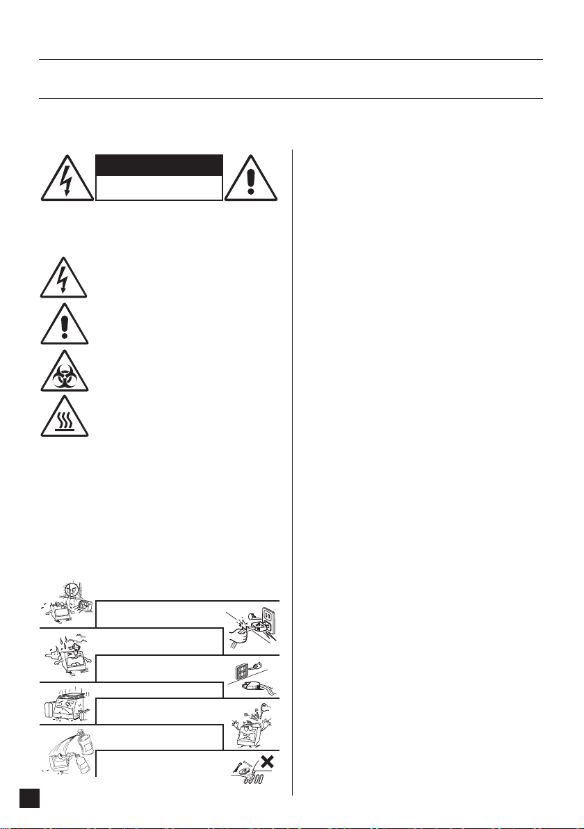
Handle the power cord carefully.
Hold the plug when unplugging the cord.
Keep the set free from moisture,
water, and dust.
Unplug the power cord when not
using the set for long periods of time.
Do not obstruct the ventilation space.
Do not let foreign objects in the set.
Do not let insecticides, benzene, and
thinner come in contact with the set.
Never disassemble or modify the set
in any way.
Avoid high temperatures.
Allow for sufficient heat dispersion when installed on a rack.
CAUTIONS
Risk Of Electric Shock
Do Not Open
Safety Precautions
Before use
These WARNINGS and CAUTIONS are intended to protect you and other persons from injuries
and damages. To ensure safe operation, please follow them carefully.
CAUTION:
To Reduce The Risk Of Electric Shock, Do Not Remove Cover (Or Back).
No Userserviceable Parts Inside. Refer Servicing To Qualified Service Personnel.
CAUTION:
1. Handle the power supply cord carefully
Do not damage or deform the power supply cord. If it is damaged or deformed, it
may cause electric shock or malfunction when used. When removing from wall
outlet, be sure to remove by holding the plug attachment and not by pulling the
cord.
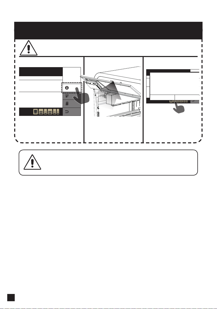
2. Do not open the top cover
In order to prevent electric shock, do not open the top cover.
3. Do not place anything inside
Do not place metal objects or spill liquid inside the MagCore®System. Electric
shock or malfunction may result.
Note On Use:
1. Read Instructions – All the safety and operating instructions should be read
before the product is operated.
2. Retain Instructions – The safety and operating instructions should be retained
for future reference.
3. Heed Warnings – All warnings on the product and in the operating
instructions should be adhered to.
4. Follow Instructions – All operating and use instructions should be followed.
5. Cleaning – Unplug this product from the wall outlet before cleaning. Only
allow to use 75% of EtOH to clean the surface of instrument.
6. Attachments – Do not use attachments not recommended by the product
manufacturer as they may cause hazards.
7. Water and Moisture – Do not use this product near water – for example, near
a bath tub, wash bowl, kitchen sink, or laundry tub; in a wet basement; or near
a swimming pool; and the like.
8. Accessories – Do not place this product on an unstable cart, stand, tripod,
bracket, or table. The product may fall, causing serious injury to a child or adult,
and serious damage to the product. Use only with a cart, stand, tripod, bracket,
or table recommended by the manufacturer, or sold with the product. Any
mounting of the product should follow the manufacturer’s instructions, and
should use a mounting accessory recommended by the manufacturer.
9. Ventilation – Slots and openings in the cabinet are provided for ventilation
and to ensure reliable operation of the product and to protect it from
overheating, and these openings must not be blocked or covered. The
openings should never be blocked by placing the product on a bed, sofa,
rug, or other similar surface. This product should not be placed in a built-in
installation such as a bookcase or rack unless proper ventilation is provided or
the manufacturer’s instructions have been adhered to.
10. Power Sources – This product should be operated only from the type of power
source indicated on the marking label. If you are not sure of the type of power
supply to your home, consult your product dealer or local power company. For
products intended to operate from battery power, or other sources, refer to the
operating instructions.
11. Grounding or Polarization – This product may be equipped with a polarized
alternating-current line plug (a plug having one blade wider than the other).
This plug will fit into the power outlet only one way. This is a safety feature. If
you are unable to insert the plug fully into the outlet, try reversing the plug. If
the plug should still fail to fit, contact your electrician to replace your obsolete
outlet. Do not defeat the safety purpose of the polarized plug.
12. Power-Cord Protection – Power-supply cords should be routed so that they
are not likely to be walked on or pinched by items placed upon or against them,
paying particular attention to cords at plugs, convenience receptacles, and the
point where they exit from the product.
13. Lightning – For added protection for this product during a lightning storm, or
when it is left unattended and unused for long periods of time, unplug it from
the wall outlet and disconnect the antenna or cable system. This will prevent
damage to the product due to lightning and power-line surges.
14. Overloading – Do not overload wall outlets, extension cords, or integral
convenience receptacles as this can result in a risk of fire or electric shock.
15. Object and Liquid Entry – Never push objects of any kind into this product
through openings as they may touch dangerous voltage points or short-out
parts that could result in a fire or electric shock. Never spill liquid of any kind on
the product.
16. Servicing – Do not attempt to service this product yourself as opening or
removing covers may expose you to dangerous voltage or other hazards. Refer
all servicing to qualified service personnel.
17. Damage Requiring Service – Unplug this product from the wall outlet and
refer servicing to qualified service personnel under the following conditions:
a) When the power-supply cord or plug is damaged,
b) If liquid has been spilled, or objects have fallen into the product,
c) If the product has been exposed to rain or water,
d) If the product does not operate normally by following the operating
instructions. Adjust only those controls that are covered by the operating
instructions as an improper adjustment of other controls may result in damage
and will often require extensive work by a qualified technician to restore the
product to its normal operation,
e) If the product has been dropped or damaged in any way, and
f)When the product exhibits a distinct change in performance
– this indicates a need for service.
18. Replacement Parts – When replacement parts are required, be sure the
service technician has used replacement parts specified by the manufacturer or
have the same characteristics as the original part. Unauthorized substitutions
may result in fire, electric shock, or other hazards.
19. Safety Check – Upon completion of any service or repairs to this product, ask
the service technician to perform safety checks to determine that the product is
in proper operating condition.
20. Heat – The product should be situated away from heat sources such as
radiators, heat registers, stoves, or other products that produce heat.
The exclamation point within an equilateral triangle isintended
to alert the user to the presence of important operating
and maintenance (servicing) instructions in the literature
accompanying the appliance.
Be aware of contaimination by contagious specimens.
High temperature warning!!
DO NOT touch the heating block with this sticker attached, it
may cause serious burning injuries.
The lightning flash with arrowhead symbol, within an
equilateral triangle, is intended to alert the user to the presence of
uninsulated “dangerous voltage” within the product’s enclosure
that may be of sufficient magnitude to constitute a risk of electric
shock to persons.
SAFETY INSTRUCTIONS

2
MagCore® HF48
Model HF48 / MCA4801 (under development)
Processing Capacity Max .48 samples per batch
System Feature 1. Special Cartridge rack, T-Rack, Tube Rack design for easy installation
2. Auto-cartridges locking
Power Supply Voltage: AC 200V ~ 220V; Frequency: 50/60Hz;
Dimension W1000 x D800 x H1600 (mm)
W39.37 X D31.49X H62.99(inches)
Net Weight 250kg / 551.25Lb
Specification
━ Operation Parameters
━ Operation Environment
━ Applications
Whole Blood (200/400ul), Viral Nucleic Acid (DNA/RNA), Tissue Genomic DNA, Plant Genomic DNA
Bacteria Kit, Total RNA Kit
Processing Capacity 1~48 samples per batch
Sample Volume 60/100/150/200 μl /1200 μl
Elution Volume 60/100/150/200 μl
Purity O.D. 1.8 -2.0 A260/280 ratio
Temperatures allowed during transportation storage packaging 15° C~35° C
Temperatures allowed during operation +18° C to +300C
Pollution Degree Indoor

3www.rbcbioscience.com
Attachments
Cartridge Rack X 6
Cartridge X 20 Sample Tube X 50 Tip / Tip Holder Set X 50
Elution Carrier X 1
Cartridge Carrier B X 1 / Cartridge Carrier A X 1
Tip Carrier B X 1 / Tip Carrier A X 1
Power Cord X 1 Lubricant X 1 O-Ring X 24
System test tools should be kept in clean places and the loss should be avoided.
System Test Tools
MagCore HF48 Totle Weight 250kg / 551.25Lb

4
MagCore® HF48
Piston Assembly
Operating Area B
Storage Cabinet and Electrical Box
Operating Area A
Elution Area
Shutter
Fixed Stands (four legs)
Fixed Bolt on the Top Cover of Part Chamber
System Overview
Cooling Fans
Power Switch and Plug
Power Switch (red)
Light Switch (green)
Part Chamber
Maintenance Cover
Status Indicator
Viewing Window
Touch Screen
Door of Viewing Window
Feeding Door
Top Cover of Part Chamber

5www.rbcbioscience.com
━ Before Installation
Installation
Please find out a flat position close to outlet and keep sufficient space for system
installation and ventilation before installation.
When installation the system, please make sure the elevation
difference by using level rail for measurement and fixed stands
for fine-tuning.
!
System Height
1600 mm
System Depth
800 mm
System Width
1000 mm
Distance from Wall (left/right)
200 mm Distance from Wall (back)
400 mm

6
MagCore® HF48
━ Install MagCore
Make sure that the voltage of
the outlet is 220V ~ 240V. Keep
hands dry. Also, make sure that
the machine remains off, and
insert the plug and then turn on
the power switch.
Please note the weight of the top
cover of part chamber. The step may
need two people to accomplish.
Please refer to the position reference shown on page 5, locate the
system in an appropriate place, put down the four fixed stands for
fine-tuning according to the ground level, and tighten fixed screws.
Shear the transportation belt and return the top cover of part
chamber.
Shear the belts on Racks.
Plug the power cord and turn on the main power.
Turn on the power (red) and the system will be initialized
automatically.
Please set the local time (refer to
page 19) for the first installation, and
perform test according to “Piston
Test” (page 15)..
Please finish reading the operation
manual before any operation!
Rotate and pull out the fixed bolts on both sides of the top cover of
part chamber by coins.
Open the top cover of part chamber by using the fixed bolts on the
top cover of part chamber as holders.
1 2
!
Next Step
Next Step
Next Step
Next Step
Next Step
Next Step

7www.rbcbioscience.com
B
A
Tip
Sample
━ Install Elution Tube
Warning:
Do NOT use any other types of centrifuge tubes to replace the Sample Tube
provided by the reagent set. The height of the Sample Tube prepared by customers
themselves may be different from that provide by the reagent set and thus results
in poor extraction result.
Warning:
Carrier of area A may be used
only in area A, whereas Carrier of
area B may be used only in area B.
Incorrect use may cause the system
inoperable because Carrier is not
detected.
━ Install Cartridge━ Install Tip and Sample Tube
B
A
Insert Tip and Sample Tube into the slots of Tip Carrier. After that,
place the entire set of Tip Carrier in the slots of A area and B area
according to marks, respectively.
Insert Cartridge into Cartridge Rack, and then place Cartridge
Rack in Cartridge Carrier. After that, place the entire set of Cartridge
Carrier in the slots of A area and B area according to marks,
respectively.
Place Elution Tube in corresponding positions according to A area
and B area, and then place Elution Carrier in Elution slot.
E
Elution A
Elution B
Elution Area
Operation Area A
Operation Area B

8
MagCore® HF48
Start
Maintenance
Load program
Setup Status
2012.06.07
12:12:12
━ Panel Functional Area
━ Main Menu
Touch Panel and User Interface
MagCore® HF48 provides 8.9-inch full-color touch screen
and easily understood user operation interface. The operator
may see the current execution status and end time of the
system by only watching the screen.
2012.06.07
12:12:12
Start
Maintenance
Loadprogram
Setup Status
Start
Stop
Save
Back
Load
Program
Start
24 Test 48 Test
DNase I Treatment
Sample Volume
Elution Volume
Please select Cartridge Code
Elution Buffer
Optical Detection
AAB B E
D
Start
Set basic setup parameters and operation …
Load Program
Load common setups stored by user …
Maintenance and other test functions
Basic maintenance, UV disinfection and mechanism test of
the system …
System time
System status
Basic message of the system, serial number, error
Setup
System time setup
Start
Stop
Save
Back
Load
Program
Start
24 Test 48 Test
DNase I Treatment
Sample Volume
Elution Volume
Please select Cartridge Code
Elution Buffer
Optical Detection
AAB B E
D
A A
A
BE
B
DA
B
B E
Undetected
Normal
Front Door
Front Door Opened
No Carry
No Carry
No Carry
No Carry
No Carry
Cartridge Carrier B
Tip Carrier B
Cartridge Carrier A
Tip Carrier A
Elution Carrier
Information
Start
Stop
Save
Back
Load
Program
Start
24 Test 48 Test
DNase I Treatment
Sample Volume
Elution Volume
Please select Cartridge Code
Elution Buffer
Optical Detection
AAB B E
D
Menu Area
Functional Operation Area
Message Prompt Area
Start
Stop
Save
Back
Load
Program
Start
24 Test 48 Test
DNase I Treatment
Sample Volume
Elution Volume
Please select Cartridge Code
Elution Buffer
Optical Detection
AAB B E
D
Start
Stop
Save
Back
Load
Program
Start
24 Test 48 Test
DNase I Treatment
Sample Volume
Elution Volume
Please select Cartridge Code
Elution Buffer
Optical Detection
AAB B E
D

9www.rbcbioscience.com
Emergency Stop and Warning
Please read this safety information such that the system can be
immediately stopped when emergency occurs.
Method 1 Method 2 Removal
Min
90
Processing
Stop
Save
Back
Load
Program
Heater B 68°C / 154.4 °F | Heater A 68°C / 154.4 °F
Heating
Test :
Cartridge Code :
Remove DNA
Sample Volumn :
Elution Volumn :
Elution Buffer :
48
105 Plasma DNA Extraction Kit (1.2 ml)
---
200
µl
150
µl
---
AB
DA
B E
Min
90
Processing
Stop
Save
Back
Load
Program
Heater B 68°C / 154.4 °F | HeaterA 68°C / 154.4 °F
Heating
Test:
Cartridge Code :
Remove DNA
Sample Volumn :
Elution Volumn :
Elution Buffer :
48
105 Plasma DNA Extraction Kit (1.2 ml)
---
200 µl
150 µl
---
AAB B E
D
Warning?
Abort
Program Stopped.
Press ABORT to terminate the process or
CONTIUNE to run.
Contiune
The system will stop all system operations
immediately if the front door is opened
when the program is under execution
because of the safety consideration.
For the removal of emergency stop,
select Continue on the screen to keep on
unfinished procedures or select Abort to
end all operations.
Press Stop key to stop all system operations
immediately if there is emergency status or the
system is desired to be interrupted when the
system is under operation.
Warning:
It is strictly prohibited from putting hands in the operation area to
prevent from injury when the system is under operation.

10
MagCore® HF48
Press Start key in the main functional window.
Select 24 or 48 test channels.
Select Cartridge number.
Cartridge number is marked on the Cartridge you use.
Please reconfirm the number you selected and select all
parameters.
Confirm that the icon in the status bar is in normal status. If
the icon shows , the Start key will be at “inactive” status and the
operation is disabled. Please follow the display portion to remove
error to solve. (Refer to page 8 for warning marks)
When you finish input and press Start key, the system will show
a confirmation window, on which there are the parameters you
input. Please press Yes to operate the system if the parameters are
not incorrect. Please press No to modify incorrect parameters if you
want to modify.
You may watch the procedure status and remained time of the
current operation on the control panel. The system will display
Complete page after completion.
━ Start
Start
Maintenance
Load program
Setup Status
2012.06.07
12:12:12
Start
Stop
Save
Back
Load
Program
Start
24 Test 48 Test
Cartridge Code
Dnase Treatmen
Elution Buffer
Sample Volume
Elution Volume
AB
DA
B E
Start
Cartridge Code
DNase I Treatment
Sample Volume
Elution Volume
Please select Optical Detrction
Optical Detection
Save
Back
Load
Program
101 MagCore Genomic DNA Whole Blood Kit (Speedy installation)
Start
Yes No
48
Test
Test:
Cartridge Code :
Remove DNA
Sample Volumn :
Elution Volumn :
Elution Buffer :
48
105 Plasma DNA Extraction Kit (1.2 ml)
---
200 µl
150 µl
---
Start
Stop
Save
Back
Load
Program
Start
24 Test 48 Test
Cartridge Code
Dnase Treatmen
Elution Buffer
Sample Volume
Elution Volume
AB
DA
B E
Please select Channel
Press START to Proceed
105 Plasma DNA Extraction Kit (1.2 ml)
200 µl
150 µl
Min
90
Processing
Stop
Save
Back
Load
Program
Heater B 68°C / 154.4 °F | Heater A 68°C / 154.4 °F
Heating
Test :
Cartridge Code :
Remove DNA
Sample Volumn :
Elution Volumn :
Elution Buffer :
48
105 Plasma DNA Extraction Kit (1.2 ml)
---
200 µl
150 µl
---
AB
DA
B E
Min
90
Processing
Stop
Save
Back
Load
Program
Heater B 68°C / 154.4 °F | Heater A 68°C / 154.4 °F
Heating
Test :
Cartridge Code :
Remove DNA
Sample Volumn :
Elution Volumn :
Elution Buffer :
48
105 Plasma DNA Extraction Kit (1.2 ml)
---
200 µl
150 µl
---
AB
DA
B E
Remained time for system operation
Heater status.
Display current operation status.
Display selected parameter items.
Emergency Stop and Cancel keys. Please
refer to the content on page 9.
Next Step
Next Step
Next Step
Next Step
It is recommended not to open the
viewing window or feeding door to
prevent from poor extraction result in
system operation if there is no emergency.
Complete
Back
Start

11 www.rbcbioscience.com
Please select one of your programs.
Check whether the parameters to be executed are correct and
press Yes to load parameters
Press Load Program key directly to enter Stored Programs page
after entering Start pagePrograms.
Please select Cartridge Code
Stored Programs
Please select Stored Program Item
Back
1 5
2 6
3 7
4 8
Stored Program 1
Stored Program 2
Stored Program 3
Stored Program 4
Stored Program 5
Stored Program 6
Stored Program 7
Stored Program 8
Stored Programs
Please select Stored Program Item
Back
1 5
2 6
3 7
4 8
Stored Program 1
Stored Program 2
Stored Program 3
Stored Program 4
Stored Program 5
Stored Program 6
Stored Program 7
Stored Program 8
Load Program?
Yes No
48
Test
Cartridge Code :
Remove DNA
Sample Volumn :
Elution Volumn :
Elution Buffer :
105 Plasma DNA Extraction Kit (1.2 ml)
---
200 µl
150 µl
---
Start
Maintenance
Load program
Setup Status
2012.06.07
12:12:12
Start
Stop
Save
Back
Load
Program
Start
24 Test 48 Test
Cartridge Code
Dnase Treatmen
Elution Buffer
Sample Volume
Elution Volume
AB
DA
B E
Please select Channel
Next Step
Next Step
Load program
Load Program
You may memorize your commonly used programs in the system by self-
defined names to simplify the convenience of system operation.
Press Load Program key to enter in the main menu to enter
Stored Programs page
Or
Press Load Program key directly to enter Stored Programs
page after entering Start page.

12
MagCore® HF48
You may memorize your 8 most commonly used programs in
memory and create names for you to remember easily.
Please press Save key to enter Stored Programs page after all
parameters have been selected on Start page.
Please select an item for creation or replacement.
Confirm the correctness of the parameters to be stored.
Enter the name you want to save and press Enter to save.
━ Save Programs
Stored Programs
Please select Stored Program Item
Back
1 5
2 6
3 7
4 8
Stored Program 1
Stored Program 2
Stored Program 3
Stored Program 4
Stored Program 5
Stored Program 6
Stored Program 7
Stored Program 8
Press Enter to send
Store Program 1
Cancel
1 2 3 4 5 6 7 8 9 0 -
Q W E R T Y U I O P
Backspace
Enter
A S D F G H J K L
Z X C V B N M
Stored Programs
Please select Stored Program Item
Back
1 5
2 6
3 7
4 8
Stored Program 1
Stored Program 2
Stored Program 3
Stored Program 4
Stored Program 5
Stored Program 6
Stored Program 7
Stored Program 8
Save Program?
Yes No
48
Test
Cartridge Code :
Remove DNA
Sample Volumn :
Elution Volumn :
Elution Buffer :
105 Plasma DNA Extraction Kit (1.2 ml)
---
200 µl
150 µl
---
Start
Stop
Save
Back
Load
Program
Start
24 Test 48 Test
Cartridge Code
Dnase Treatmen
Elution Buffer
Sample Volume
Elution Volume
AB
DA
B E
Please select Channel
You may delete your commonly used parameters from memory.
Please press Load Program key to enter Stored Programs page
after entering Start page.
Please select an item you want to delete by pressing X.
Confirm the correctness for the deletion of parameters and press
Yes to complete the deletion.
━ Delete Programs
Stored Programs
Please select Stored Program Item
Back
1 5
2 6
3 7
4 8
Stored Program 1
Stored Program 2
Stored Program 3
Stored Program 4
Stored Program 5
Stored Program 6
Stored Program 7
Stored Program 8
Stored Programs
Please select Stored Program Item
Back
1 5
2 6
3 7
4 8
Stored Program 1
Stored Program 2
Stored Program 3
Stored Program 4
Stored Program 5
Stored Program 6
Stored Program 7
Stored Program 8
Delete Program?
Yes No
48
Test
Cartridge Code :
Remove DNA
Sample Volumn :
Elution Volumn :
Elution Buffer :
105 Plasma DNA Extraction Kit (1.2 ml)
---
200 µl
150 µl
---
Start
Stop
Save
Back
Load
Program
Start
24 Test 48 Test
Cartridge Code
Dnase Treatmen
Elution Buffer
Sample Volume
Elution Volume
AB
DA
B E
Please select Channel
Next Step Next Step
Next Step
Next Step
Next Step

13 www.rbcbioscience.com
Copy new programs in USB Flash Driver.
* Confirm the existence of "48ExtractorUpdateProgram" directory
in USB Flash Driver
Open the door of viewing window, insert USB Flash Driver (prepared
by customer) into the USB slot on the back of the control panel, and
press Export key to export data to USB Flash.
Select Update Program Files.
Press Yes to start update and the window will be closed
automatically after the update is completed.
Maintenance
Please select Item
Back
UV Sterilization Moving Test
Heater Test
Rejection Tip
Piston Test
O-Ring & Piercing Needles
DC Motor Operate Update Program Files
Maintenance
Please select Item
Back
UV Sterilization Moving Test
Heater Test
Rejection Tip
Piston Test
O-Ring & Piercing Needles
DC Motor Operate Update Program Files
Maintenance
Please select Item
Back
UV Sterilization Moving Test
Heater Test
Rejection Tip
Piston Test
O-Ring & Piercing Needles
DC Motor Operate Update Program Files
Easy Maintenance is for user’s maintenance items, including systems such as
sterilization, cleaning, easy test and error message report. User has to arrange
maintenance items regularly to make sure that the system is in good status.
Update Program Files
UV Sterilization
UV Sterilization
Piston Test
Piston draining and leakage test
Moving Test
Continuously moving test for each component
Heater Test
Temperature test for heater
Rejection Tip
Make Tip rejection back to origin and system
rejection
Update Program Files
Update programs
O-Ring and Piercing Needles
Procedures for Replacing O-Ring and cleaning
piercing needles
DC Motor Operate
Raise or lower the protective cover of Elution
and motor in AB area
Maintenance
Easy Maintenance
Please scan virus before insert
USB Flash Driver.
Please do NOT change any file
content in the directory
48ExtractorUpdateProgram.
Update Program Files?
Yes No

14
MagCore® HF48
Select Replace O-Rings item and press START key to start.
Follow the prompted step Use a sharp blade to cut off old O-ring.
Press NEXT after completion.
Apply new O-ring.
Press Finish to complete after lubricant is coated.
Replace O-Rings Clean Piercing Needles
Start
Stop
O-Ring & Piercing Needles
Select item and Press Start to run
Back
━ Replace O-Rings
Replace O-Rings Clean Piercing Needles
Start
Stop
O-Ring & Piercing Needles
Select item and Press Start to run
Back
Next
Replace O-Rings Step 1
Use a shap blade to cut off old O-ring.
Replace O-Rings Clean Piercing Needles
Start
Stop
O-Ring & Piercing Needles
Select item and Press Start to run
Back
Next
Replace O-Rings Step 2
Apply with new one.
Replace O-Rings Clean Piercing Needles
Start
Stop
O-Ring & Piercing Needles
Select item and Press Start to run
Back
Finish
Replace O-Rings Step 3
Use supplied lubricating oil to rub a thin layer around O-Rings.
Select Clear Piercing Needles, and press START to start.
Please prepare a cotton paper with 70% alcohol added to clean.
Replace O-Rings Clean Piercing Needles
Start
Stop
O-Ring & Piercing Needles
Select item and Press Start to run
Back
━ Clean Piercing Needles
Replace O-Rings Clean Piercing Needles
Start
Stop
O-Ring & Piercing Needles
Select item and Press Start to run
Back
Finish
Clean Piercing Needles
Piercing Needles are positioned and stopped, use 70% alcohol with cotton paper to clean.
Next Step
Next Step
Next Step
Next Step
Please do NOT use detergent
other than 70% alcohol to
clean.
Piercing needles are very sharp,
please do not hurt your hands!

15 www.rbcbioscience.com
Select Piston test in Maintenance menu.
Please place the “system test tool” prepared in advance in A area
(please refer to page 7), wherein put water of 1ml in empty Sample
Tube, after that, select Start to start test.
The purpose of this step is mainly to test the smoothness when
the system takes up TIP.
The display shows Piston Test Step 1. The system will move to take
up TIP. Please check whether TIP is taken up smoothly. If you find
any sticking phenomena, please press Abort to stop test and move
the stuck TIP back to Tip Holder and execute the program again.
If the problem happens continuously, please contact your local
dealer to handle. Press Next to go to the next step for test if the
taking up is smooth.
The purpose of this step is mainly to test TIP leakage of the sytem.
The system will absorb water from Sample Tube. Please check
whether the liquid levels of each TIP are at the same horizontal or
there is a gradually lowering situation. If the liquid levels are not at
the same horizontal or there is a lowering situation, please press
Finish to test again. If the problem happens continuously, please
refer to page 14 to replace new O-Ring for problematic Piston
and test this item again after replacement. If the problem is still
not solved, please contact local dealer to handle.
━ Piston Test
Maintenance
Please select Item
Back
UV Sterilization Moving Test
Heater Test
Rejection Tip
Piston Test
O-Ring & Piercing Needles
DC Motor Operate Update Program Files
Start
Stop
Piston Test
Press START to run
Back
AB
DA
B E
Replace O-Rings Clean Piercing Needles
Start
Stop
O-Ring & Piercing Needles
Select item and Press Start to run
Back
Next Abort
Piston Test Step 1
Machine taking up Tips, please check whether the Tips move smoothly. If you observe a Tip Holder
stuck, please press the STOP button immediately to stop and remove the jammed Holder.
Replace O-Rings Clean Piercing Needles
Start
Stop
O-Ring & Piercing Needles
Select item and Press Start to run
Back
Finish
Piston Test Step 2
Tip will absorb water from Sample Tube, please check the liquid level of each columns are
at same horizontal.
Next Step
Next Step
Next Step

16
MagCore® HF48
Please place the Cartridge for test prepared in advance on
the Cartridge Rack for it to be located in the system and insert
thermometer into it after the water of 500µl is put in heat block well
1 (indicated by the arrow)
Select Heater Test in Maintenance menu.
Press Start to start test. Concurrently, the touch screen shows the
heater temperature tested currently by the system. Please compare
to see if the temperature of your thermometer is the same.
Please press Stop key if you want to stop test.
Maintenance
Please select Item
Back
UV Sterilization Moving Test
Heater Test
Rejection Tip
Piston Test
O-Ring & Piercing Needles
DC Motor Operate Update Program Files
━ Heater Test
Start
Stop
Heater Test
Press START to run
Back
Heater A : 65°C / 148°F
Heater B : 65°C / 148°F
This function is mainly for the system to perform rejection after
emergency stop or operation interrupt due to outage etc.
Select Rejection Tip in Maintenance menu
Please select Start to start the process of Rejection Tip. After the
process is completed, the system will be rejected to position
automatically.
Maintenance
Please select Item
Back
UV Sterilization Moving Test
Heater Test
Rejection Tip
Piston Test
O-Ring & Piercing Needles
DC Motor Operate Update Program Files
━ Rejection Tip
Start
Rejection Tip
Press Start to rejection tip
Back
Rejection B Area Tip Rejection A Area Tip
AB
DA
B E
Next Step
Next Step
heat block well 1
There difference between the
temperature of the thermometer and
that of the heater in the machine.
!

17 www.rbcbioscience.com
Select UV Sterilization in Maintenance menu.
You may select 30min or 60min process in UV Sterilization menu.
Press START key to start sterilization after selection. The touch
screen will show the remaining time of sterilization at the same time
and will show Complete picture after the sterilization is completed.
Please press Stop to stop if you want to stop sterilization.
Maintenance
Please select Item
Back
UV Sterilization Moving Test
Heater Test
Rejection Tip
Piston Test
O-Ring & Piercing Needles
DC Motor Operate Update Program Files
Start
Stop
30min 60min
UV Sterilization
select Item and press START to run
Back
30:00
Remaining Time
Complete
Back
━ UV Sterilization
Open the top cover of the part chamber.
Apply new UV lamp.
Select Status key in the main menu and press UV Time Reset key to
reset the hours of UV lamp.
Please test to see if UV lamp is normal after replacement.
━ Replace UV Lamp
Next Step
Next Step
Next Step
Please note the weight of the
top cover of the part chamber.
This step may need two people
to complete.
Status
Back
System Date : 2012.12.12
System Time : 12:12:12
UV Lamp Operating Time : Hr:00 Min:00 Sec:00
UI Software Ver. : Ver.SUPER2012-0.1
PLC Software Ver. : Ver.SUPER2012-0.1
Machine serial number :
Error history list
UV Time Reset

18
MagCore® HF48
Select Moving Test in Maintenance menu.
Select the items needed to test. Press Start to start test. The motor
will run continuously until user press Stop.
Select DC Motor Operate in Maintenance menu.
All consumables are fixed in the system when test is stopped.
As it is necessary, this control interface may be used to move up
and down the operating area manually to take out consumables
conveniently.
Refer to the area arrangement shown in page 7 for up/down area.
Select the area you want to move up or down and press Start to
start up/down. It will stop automatically as the motor moves to the
peak point.
Maintenance
Please select Item
Back
UV Sterilization Moving Test
Heater Test
Rejection Tip
Piston Test
O-Ring & Piercing Needles
DC Motor Operate Update Program Files
Maintenance
Please select Item
Back
UV Sterilization Moving Test
Heater Test
Rejection Tip
Piston Test
O-Ring & Piercing Needles
DC Motor Operate Update Program Files
Moving Test
Please select Item
Back
X Asix Moveing Test Y Asix Moveing Test
M Asix Moveing TestV Asix Moveing Test
ALL Asix Moveing Test
Stop
Start
DC Mortor Operate
Please select Item
Back
Opretion Area A UP Opretion Area A DOWN
Opretion Area B DOWN
Shutter Close
Opretion Area B UP
Shutter Open
Start
━ Moving Test ━ DC Motor Operate
Next Step Next Step
X axis motor running test Operation Area A UP
Shutter Open
Operation Area B UP
Y axis motor running test Operation Area A DOWN
Shutter Close
Operation Area B DOWN
M axis motor running test
V axis motor running test
Running tests for all axes in turn

19 www.rbcbioscience.com
Setup
Select the items you want to change.
Enter setting value and press Enter to confirm.
Press Enter to send
2012
Cancel
1 2 3 4 5 6 7 8 9 0 -
Q W E R T Y U I O P
Backspace
Enter
A S D F G H J K L
Z X C V B N M
━ System Timing Setting
Start
Maintenance
Load program
Setup Status
2012.06.07
12:12:12
Time Setting
Back
Year : 2012 24 h
Hour : 12
Minute : 12
Month : 12
Day : 03
Year Setting
Month Setting
Day Setting
12 or 24 hour form may be set
Minute Setting
Hour Setting
Next Step
Next Step
Setup
You may set timing here.
Other manuals for MagCore HF48
2
Table of contents
Other RBCBioscience Laboratory Equipment manuals
Popular Laboratory Equipment manuals by other brands

Hettich
Hettich ROTANTA 460 Robotic operating instructions

Mind Peak
Mind Peak WaveRider operating manual

C.B.S. SCIENTIFIC
C.B.S. SCIENTIFIC DGGE-1001 instruction manual

Datalogic
Datalogic EOX 30W Quick installation guide

Cole Parmer
Cole Parmer PCRmax Alpha Cycler 1 Operation manual

Sonel
Sonel KT-165 user manual

Radleys
Radleys Reactor-Ready Lab Reactor instructions

Qiagen
Qiagen EZ2 Connect Safety Instructions and Quick Start Guide

DMT
DMT 320A user guide

Hach
Hach LT 200 user manual

Ocean Optics
Ocean Optics USB4000 Installation and operation manual

Agilent Technologies
Agilent Technologies 1100 Series Reference manual