RC4WD Diablo User manual
Version 1.1
RC4WD Diablo
Instruction Manual
Thank you for your purchase. Welcome to the RC4WD family. This kit is a combination of many
specially engineered and manufactured parts. En oy your build.
This is a complete instruction manual for the Diablo truck kit. We have tried to detail as many
things in the build process as possible. Since the kit has so many options available it is hard to cover
all of them. This manual covers the basic kit.
If for some reason you don’t find enough detail here, or you are having issues with your build please
visit RC4WD Diablo forum here.
You will need to have a few things for this build.
Metric Hex Wrenches
Regular Wrenches, or Nut Drivers
Pliers
Monster Lube RC4WD #X-0317
Blue Thread locker
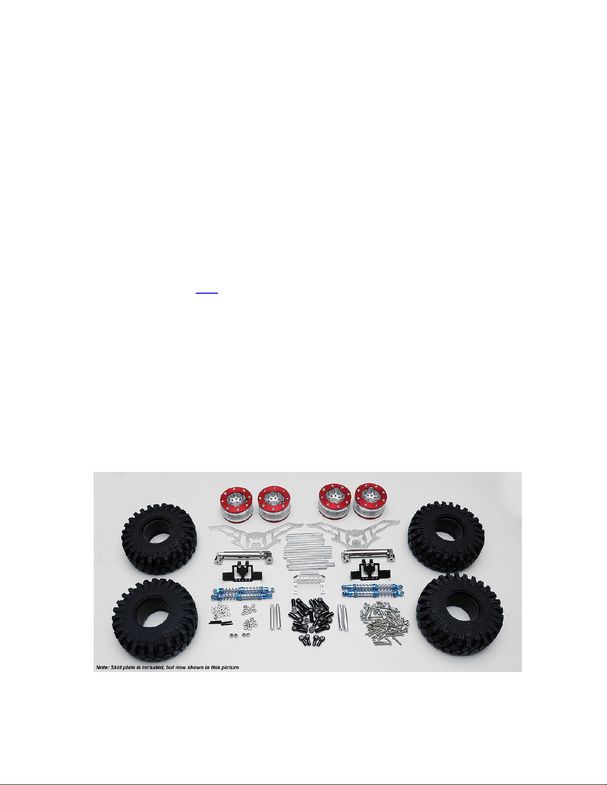
The first thing you will want to do is unpack your truck kit. Be careful with the parts when
unpacking and make sure to inventory all your items.
Skid plate and axles not shown in photo.

When you build this kit you will want to use some Blue thread locker on the metal to metal parts.
The included nuts have nylon inserts to prevent them from backing off, but all other metal to metal
surfaces will stay in place better with the thread locker. Anytime you see an *, this notes the need
for thread locker. (please be sure to get blue thread locker, it is removable.)
Hardware Listing
(20) M3 Nylock nut
(2) Black Motor Screws
(4) M3 X 16mm SSS
(28) M3 conical washers
(4) 4mm spacers
(4) M3 X 25mm SHCS
(8) 6mm Spacers
(20) M3 X 20mm SSS
(7) M3 X 20mm SHCS
(10) M3 X 16mm SHCS (5) M3 X 12mm SHCS (4) M3 X 10mm SHCS
(30) M3 X 8mm SHCS (4) M3 X 30mm SHCS
Miscellaneous parts listing
(5) 90mm long Silver links (8) 70mm long Silver links (1) 33mm long Silver link
(4) Body posts (1) Bottom Skid (16) Black straight Rod ends
(4) Curved rod ends (4) Velcro Straps
Assembly Steps
Step 1. Transmission shaft change
In this step we will be removing the long shaft from the R2 tranny and install the new short shaft.
This step is a delicate step, so take you time and be careful to what the gear placement inside the
tranny.
Remove the 4 screws on the side with the long shaft. Gently work the cover off. Make sure to hold
the long shaft in place while pulling the cover off.
Once the cover is off, remove the main shaft with the gear attached. It may require you to move the
second gear out of the way. Please make sure the bushing and small brass sleeves stay in place. After
you remove the long shaft, then slide the short shaft back into the same place. Once again, make
sure everything is in its place and the gears are turning correctly.

Now you can replace the tranny cover and use the same screws to secure it.
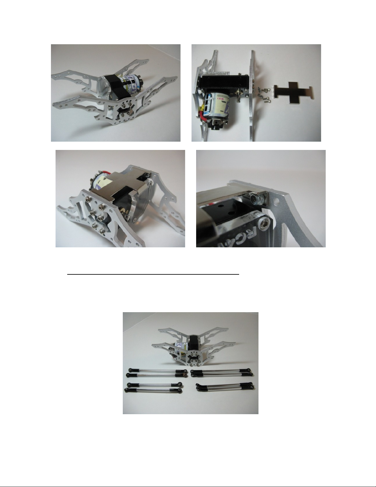
Step 2. Motor Installation
Now we need to install the motor into the R2 tranny. Use an Allen wrench to install the set screw
into the Pinion gear supplied. Then install the Pinion gear onto the motor and tighten the set screw.
If the motor has the flat on the shaft, make sure and align the set screw up with the flat of the motor
shaft.
Next install the motor into the tranny on the side with the small hole. Using the black motor screws
supplied insert the screws thru the holes in the tranny then into the motor. Make sure to tighten the
screws only part way. You will want to align the pinion and R2 gear mesh, then tighten the screws
all the way down.
Proper gear mesh can make the R2D gears last a long time, and will reduce gear noise. If you set the lash to tight it will wear
the gears and be ery loud. The mesh in the photo is just about right. You will want to use some Monster Lube to lubricate the
gears. More lube is better.
At this point the shafts will be almost impossible to turn by hand.
You can now install the clear cover like shown in the next photos. Remove the two screws
highlighted in the first photo. You will use these same screws to install the clear cover.

Step 3. Link Assembly
A. You can now assemble the links. The lower links are first. Pull out (8) Black Long straight M3
Rod ends, (12) M3 X 20mm SSS, (4) M3 X 16mm SSS, and (4) 90mm long links. You can insert the
set screws into the rod ends and then assemble into each end of the link. * They should look like the
rods in the center of the second photo.
The upper links use the curved rod ends. You can get (4) Black long straight M3 Rod ends, (4)
Black curved M3 Rod ends, (4) M3 X 20mm SSS, (4) M3 X 16mm SSS and (4) 70mm long links.
You can insert the 20mm set screws into the straight rod ends, and the 16mm set Screws into the
curved rod ends. * Install one of each curved rod end into each of the links. * Then you can install
the straight rod end onto the other side. They should look like the link on the bottom of the second
photo.
B. Onto the steering links. These are ust as easy to assemble. Use (4) Black Long straight M3 Rod
ends, (4) M3 X 20mm SSS, (1) 90mm long links, and (1) 33mm short link. You can insert the set
screws into the rod ends and then assemble into each end of the link. * They should look like the
rods in the second photo.

Step 4. Shock Fluid
You can now fill your shocks with fluid. This is a simple thing. You can remove the shock cap and
put your favorite shock fluid into the shock. Make sure that all the bubbles and air is out of the
shocks before you reinstall the cap. Make sure they shocks are not locked and then set them aside
for final assembly.
Step 5. Axle Lubrication
Lubrication of the axle gears is a very important step in the assembly of your kit. Remove the
screws holding the cover onto the axles (like in the second photo). Use some Monster Lube on the
main gear, and reinstall the cover. Be careful not to tighten the screws to much, you can strip the
plastic.
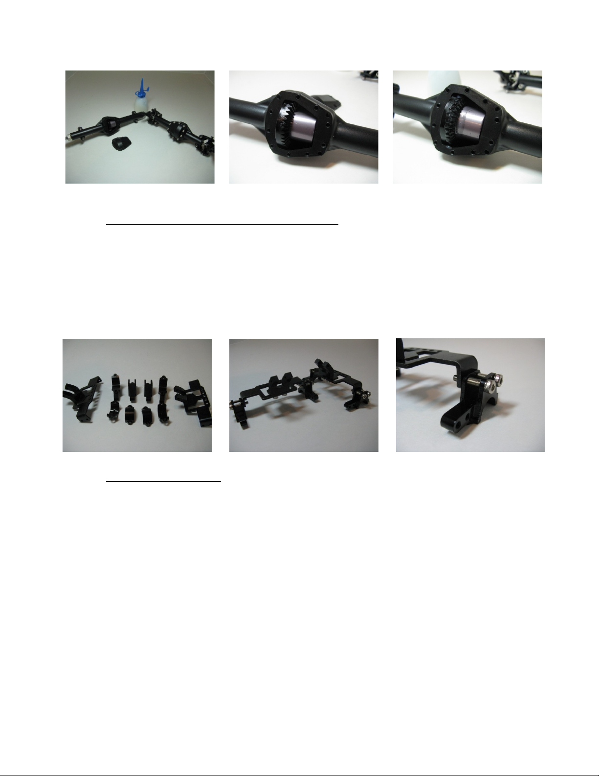
(There are washers included with the axles. Use these as shims if needed)
Step 6. Axle Servo 4 Link mount assembly
You will need to find the upper part of the 4 link mounts for the axles and both servo mounts. You
will also need (4) M3 X 12mm SHCS, and (4) M3 X 16mm SHCS. You can install each lower 4 link
mount to the sides of the servo mounts. Use the M3 X 12mm SHCS in the back hole and the M3 X
16mm in the front hole. * Make sure that the link mounts are all facing the same way like in the
second photo. Once these are installed on the axles they can’t be changed unless removed from the
axles.
Step 7. Chassis assembly
Now we can move onto main chassis assembly. You will need the R2 transmission, and Diablo side
plates and the lower skid plate. You will also need to get (12) M3 X 8mm SHCS, and (4) M3 nylock
nuts.
You can install one side of the Diablo chassis at a time using (4) M3 X 8mm SHCS on each side. * It
only lines up one way. Before installing the other chassis plate, install the lower skid with (2) M3 X
8mm SHCS and (2) M3 nylock nuts. Once again, the chassis only allows the skid in one spot for
mounting.
Now you can install the other Diablo chassis plate the same way you did the first using the
remaining screws. *
Step 8. 4 Link Placement onto the Diablo chassis
Here you can install the front and rear 4 links to the Diablo Chassis. This will require several pieces
of hardware.

A. You can install the upper links first. In this step it may be easiest to turn the chassis over on its
top. We will be using the 4 links that have the curved rod ends. You will need (3) M3 X 20mm
SHCS, (1) M3 X 16mm SHCS, (4) M3 conical washers, and (4) M3 nylock nuts.
Install the link on the motor side first. We will be installing in the second hole highlighted in the
photo below.
Install the only M3 X 16mm SHCS into one of the curved rod ends. Then install a M3 conical
washer with the beveled face toward the rod end. Then insert the screw into the second hole on the
motor side like in the second photo. This will go on the outside of the chassis. Install the M3 nylock
nut to secure the link. (Add a little thread locker to the nut before installing. This will help secure the
bolt.)
Now you can use the M3 X 20mm SHCS and install the rest of the upper links. Use a conical washer
on each one making sure the bevel is toward the rod end. Be sure that the curved end is attached to
the chassis. Then use the M3 nylock nuts to secure the links.
B. Now you can install the lower links to the Diablo chassis. Use the remaining 4 long links for this
step. You will also need (4) M3 X 25mm SHCS, (4) nylock nuts, (4) M3 conical washers, (4) 6mm
spacers and (4) 4mm spacers.
Insert a M3 X 25mm SHCS into the chassis were marked in the first photo. Install a 6mm spacer,
then a 4mm spacer, and now a M3 conical washer with the bevel to the screw end. Slide the rod end
onto the screw and then secure with a M3 nylock nut. Do the same for the other 3 links.
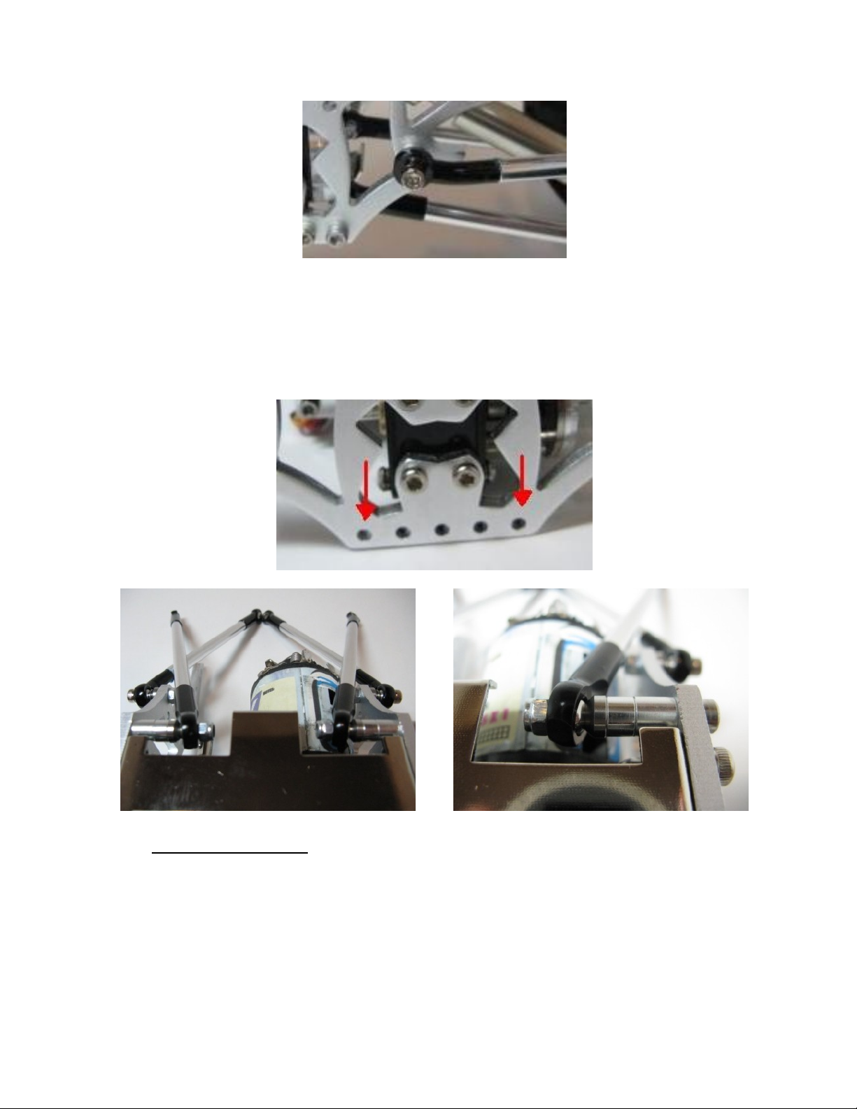
Step 9. Shock mounting
You can now install the shocks to the Diablo chassis. You will need the 4 dual stage shocks, (2)
70mm links, (4) M3 X 16mm SHCS, and (4) M3 conical washers.
The 70mm links are support shafts for the chassis. These 2 will run in between where the shocks are
mounted.
Insert the M3 X 16mm SHCS into the top of the shock body, then install a M3 conical washer with
the beveled edge toward the shock. Insert the screw into the second hole like shown in the photo

below and tighten into the support shaft. * Repeat this step 3 more times using the same screws and
into the same holes.
Step 10. 4 Link Placement/Shocks onto servo mounts
Now you can install the front and rear 4 links to the servo mounts. More hardware is needed here
too.
A. Install the upper links first. You need (4) M3 X 20mm SHCS, (4) 6mm spacers, and (4) M3
conical washers. Insert a M3 X 20mm SHCS into the end of an upper 4 link. Then insert a M3
conical washer onto the screw and follow it with a 6mm spacer. Install the screw into the top mounts
of the servo mount like shown below. * Repeat this step 3 more times. *

B. The lower links and shocks can be mounted to the lower 4 link mounts. You will need (4) M3 X
30mm SHCS, (12) M3 conical washers, and (4) M3 nylock nuts.
Insert a M3 X 30mm SHCS into the end of the shock end. Then slide a M3 conical washer onto the
screw with the beveled edge facing the shock end. Install the screw into the second hole of the lower
4 link mount like shown in the photos below. Slide another M3 conical washer onto the screw with
the beveled face out. Now slide the lower 4 link onto the screw and follow up with another M3
conical washer with the bevel face toward the rod end. Use a M3 nylock nut to secure the fastener.
You should have something that looks like this.

Step 11. Installation of the axles
Now is time to decide which way the motor will be placed on your truck. Some prefer the motor to
be placed toward the front, while other may run it toward the rear. Once you decide you will be
ready to install the axles.
Use (8) M3 X 8mm SHCS to install the lower 4 link mounts. The lower 4 link mounts have a small
lip inside them shown in the first photo. The lip lines up with a groove on the bottom of the axles.
Put the axle up to the servo mount making sure the grooves are facing down. Install the lower
mount using the M3 X 8mm SHCS. *
Step 12. Servo and Servo Mount Install
You will use (2) M3 X 8mm SHCS to install the front servo mount. * Line the servo mounts up
similar to the photo below. This may require some repositioning once you install the servo and
steering links.

To install your servo you can use (4) M3 X 10mm SHCS, and (4) nylock nuts like shown below.
Step 13. Installation of the Punisher shaft
You can now install the Punisher shafts that were included with your kit. These already have the set
screws installed into them. You may want to use a small amount of thread locker on the set screws
when installing the shafts.
The female shaft needs to be installed to the axle. While the male side attaches to the transmission

Step 14. Installing the Front Steering links
You will need the steering links you made earlier in the build. You also need (1) M3 X 16mm SHCS,
and (1) M3 X 12mm SHCS. Install the M3 X 16mm SHCS into one end of the short link and install
into the end of the long link. You can now install the screw into the steering knuckle like shown in
the first photo below. Use the M3 X 12mm SHCS to secure the other end of the long link to the
opposite steering knuckle.
You can use your own hardware to attach the short link to your servo arm.
Step 15. Bracing and body mounts
You can use the additional 70mm links to support the Diablo chassis. Use (4) M3 X 8mm SHCS to
secure the links. *
The body mounts included in the kit use (4) M3 X 8mm SHCS. * You may install them anywhere
you like.

Step 17. Wheel and Tire Installation
Make sure when mounting the tires on any wheel that you look at the tread pattern and make
sure that when the wheels are installed that each are facing the right direction.
It will take a little work to install your tires to the beadlock wheels. Remove all the screws on the
front and back ring. Wrap the tire over the wheel and then insert the bead into the outer ring of
the wheel. Carefully place the ring back on and reinstall the screws. I use a cross pattern and
carefully tighten the screws slowly. Make sure not to tighten anyone screw all the way down.
This will cause the bead to come out of its seat. Repeat for both the front and rear rings and the
other 3 wheels and tires.
After you have your tires mounted, you can remove the nuts and washers from the axles and
install the wheels to your Diablo. It should look something like this.
You will need to install your body and the rest of your electronics. Please understand that the
steering servo will require some ad ustment to work properly. When you install your Radio and
ESC you will need to refer to there operating manuals for proper setup.


Table of contents
Other RC4WD Toy manuals

RC4WD
RC4WD VV-JD00058 User manual

RC4WD
RC4WD Trail Finder 2 User manual

RC4WD
RC4WD TRAILFINDER 2 User manual

RC4WD
RC4WD Gelande II RTR D90 User manual

RC4WD
RC4WD Trail Stomper User manual

RC4WD
RC4WD VV-JD00035 User manual

RC4WD
RC4WD BEAST II User manual

RC4WD
RC4WD VV-JD00056 User manual

RC4WD
RC4WD VV-JD00071 User manual

RC4WD
RC4WD VV-JD00015 User manual


 manual")


