RCF dm41 User manual


2
ITALIANO
IMPORTANTE - Prima di collegare ed utilizzare questo prodotto,
leggere attentamente le istruzioni contenute in questo manuale, il quale è
da conservare per riferimenti futuri. Il presente manuale costituisce parte
integrante del prodotto e deve accompagnare quest’ultimo anche nei
passaggi di proprietà, per permettere al nuovo proprietario di conoscere le
modalità d’installazione e d’utilizzo e le avvertenze per la sicurezza.
L’installazione e l’utilizzo errati del prodotto esimono la RCF S.p.A. da ogni
responsabilità.
ITALIANO
ATTENZIONE: Per prevenire i rischi di fiamme o scosse elettriche, non
esporre il diffusore alla pioggia o all’umidità ed alle polveri, salvo il caso in
cui questo sia stato espressamente progettato e costruito con un grado
di protezione IP adeguato (evidenziato nella documentazione tecnica del
dispositivo).
AVVERTENZE PER LA SICUREZZA
1. Tutte le avvertenze, in particolare quelle relative alla sicurezza, devono
essere lette con particolare attenzione, in quanto contengono importanti
informazioni.
2. La linea diffusori (uscita dell’amplificatore) può avere una tensione
sufficientemente alta (es. 100 V) da costituire un rischio di folgorazione per
le persone: non procedere mai all’installazione o alla connessione del
diffusore quando la linea diffusori è in tensione.
3. Assicurarsi che tutte le connessioni siano corrette e che la tensione
d’ingresso (in un sistema a tensione costante) oppure l’impedenza del
diffusore sia compatibile con le caratteristiche d’uscita dell’amplificatore.
4. Accertarsi che la linea diffusori non possa essere calpestata o schiacciata
da oggetti, al fine di salvaguardarne la perfetta integrità.
5. Impedire che oggetti o liquidi entrino all’interno del prodotto, perché
potrebbero causare un corto circuito.
6. Non eseguire sul prodotto interventi / modifiche / riparazioni se non
quelle espressamente descritte sul manuale istruzioni.
Contattare centri di assistenza autorizzati o personale altamente qualificato
quando:
• Il diffusore non funziona (o funziona in modo anomalo);
• il cavo è danneggiato;
• oggetti o liquidi sono entrati nel diffusore;
• il diffusore non è più integro (a causa di urti / incendio).

ITALIANO
3
7. Nel caso che dal diffusore provengano odori anomali o fumo, togliere
immediatamente la tensione dalla linea diffusori e poi scollegare il
diffusore.
8. Non collegare a questo diffusore apparecchi ed accessori non previsti.
Quando è prevista l’installazione sospesa, utilizzare solamente gli appositi
punti di ancoraggio e non cercare di appendere il diffusore con elementi
non idonei o previsti allo scopo.
Verificare inoltre l’idoneità del supporto (parete, soffitto, struttura ecc.) e
dei componenti utilizzati per il fissaggio (tasselli, viti, staffe non fornite da
RCF ecc.) che devono garantire la sicurezza dell’impianto / installazione
nel tempo, anche considerando, ad esempio, vibrazioni meccaniche
normalmente generate da un trasduttore.
9. La RCF S.p.A. raccomanda vivamente che l’installazione di questo
prodotto sia eseguita solamente da installatori professionali qualificati
(oppure da ditte specializzate) in grado di farla correttamente e
certificarla in accordo con le normative vigenti.
Tutto il sistema audio dovrà essere in conformità con le norme e le
leggi vigenti in materia di impianti elettrici.
10. Vi sono numerosi fattori meccanici ed elettrici da considerare quando si
installa un sistema audio professionale (oltre a quelli prettamente acustici,
come la pressione sonora, gli angoli di copertura, la risposta in frequenza,
ecc.).
11. PERDITA DELL’UDITO
L’esposizione ad elevati livelli sonori può provocare la perdita permanente
dell’udito. Il livello di pressione acustica pericolosa per l’udito varia
sensibilmente da persona a persona e dipende dalla durata dell’esposizione.
Per evitare un’esposizione potenzialmente pericolosa ad elevati livelli di
pressione acustica, è necessario che chiunque sia sottoposto a tali livelli
utilizzi delle adeguate protezioni; quando si fa funzionare un trasduttore in
grado di produrre elevati livelli sonori è necessario indossare dei tappi per
orecchie o delle cuffie protettive.
Consultare i dati tecnici contenuti nel manuale istruzioni per conoscere la
massima pressione sonora che il diffusore acustico è in grado di produrre.
12. I diffusori devono essere collegati in fase (corrispondenza delle
polarità +/- tra amplificatori e diffusori) in modo da garantire una corretta
riproduzione audio, soprattutto quando i diffusori sono collocati in
posizione fra loro adiacente o nello stesso ambiente.

4
ITALIANO
13. Per evitare che fenomeni induttivi diano luogo a ronzii, disturbi e
compromettano il buon funzionamento dell’impianto, le linee diffusori
non devono essere canalizzate insieme ai conduttori dell’energia elettrica,
ai cavi microfonici, alle linee di segnale a basso livello che fanno capo ad
amplificatori.
14. Il cavo per il collegamento del diffusore dovrà avere conduttori di
sezione adeguata (possibilmente intrecciati, per minimizzare gli effetti
induttivi dovuti all’accoppiamento con campi elettro-magnetici circostanti)
ed un isolamento idoneo.
PRECAUZIONI D’USO
• Collocare il diffusore lontano da fonti di calore.
• Non forzare mai gli organi di comando (tasti, manopole ecc.).
• Non usare solventi, alcool, benzina o altre sostanze volatili per la
pulitura delle parti esterne.
• Se il diffusore viene utilizzato in ambienti particolarmente freddi,
pilotarlo con un segnale a basso livello per 5-10 minuti, prima di
utilizzarlo alla massima potenza.
RCF S.p.A. Vi ringrazia per l’acquisto di questo prodotto,
realizzato in modo da garantirne l’affidabilità e prestazioni
elevate.
DM41 e DM61 sono diffusori compatti a due vie progettati per sistemi a
tensione costante. Questi diffusori consentono una riproduzione del suono
naturale ed aperta, ideale per i sistemi PA e per la diffusione di musica di
sottofondo in ambienti interni ed esterni.
I collegamenti si effettuano tramite il cavo d’ingresso a due conduttori, che
fuoriesce posteriormente dal diffusore; la selezione della potenza si effettua
tramite un commutatore rotativo posto sempre nella parte posteriore del
diffusore stesso.
I diffusori sono dotati di una griglia di protezione e di un accessorio per
l’installazione a muro.

ITALIANO
5
INSTALLAZIONE
• Si raccomanda di eseguire un’installazione sicura del diffusore,
controllando che la superficie di fissaggio abbia una resistenza e solidità
tale da supportare il peso del diffusore, in modo da evitare cadute che
potrebbero compromettere l’incolumità di persone o strutture.
• Non serrare eccessivamente le viti per il fissaggio del diffusore, per
non rischiare di danneggiare gli inserti filettati M6. L’installazione
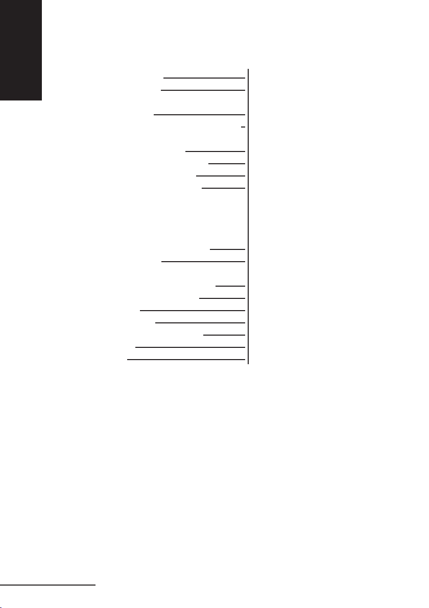
dell’accessorio si articola nei punti seguenti (vedi figura 1):
1. Utilizzando 2 tasselli (non forniti),
fissare il supporto nel punto prescelto
sulla parete. I tasselli da utilizzare devono
essere accuratamente scelti in base al
tipo di parete (cartongesso, mattoni
forati, mattoni pieni, calcestruzzo,
rivestimento in legno perlinato, ecc.).
2. Accoppiare il diffusore al supporto,
avvitando le 2 manopole P fornite in
dotazione negli inserti filettati M6 del
diffusore, senze serrare le manopole.
3. Regolare l’inclinazione del diffusore e
serrare quindi le manopole stesse P .
ATTENZIONE: Non collegare a questo diffusore apparecchi ed accessori
non previsti. Quando è prevista l’installazione sospesa, utilizzare solamente
gli appositi punti di ancoraggio e non cercare di appendere il diffusore con
elementi non idonei o previsti allo scopo.
Verificare inoltre l’idoneità del supporto (parete, soffitto, struttura ecc.) e
dei componenti utilizzati per il fissaggio (tasselli, viti, staffe non fornite da
RCF ecc.) che devono garantire la sicurezza dell’impianto / installazione
nel tempo, anche considerando, ad esempio, vibrazioni meccaniche
normalmente generate da un trasduttore.
La RCF S.p.A. raccomanda vivamente che l’installazione di questo prodotto
sia eseguita solamente da installatori professionali qualificati (oppure da
ditte specializzate) in grado di farla correttamente e certificarla in accordo
con le normative vigenti. Tutto il sistema audio dovrà essere in conformità
con le norme e le leggi vigenti in materia di impianti elettrici.
fig. 1 P
P

6
ITALIANO
COLLEGAMENTI
Per evitare il rischio di shock elettrici, non collegare il diffusore con
l’amplificatore acceso.
Prima di far funzionare il diffusore verificare attentamente la correttezza
dei collegamenti, per evitare che cortocircuiti accidentali possano dare
luogo a scintille elettriche. Il diffusore può essere collegato a linee audio a
tensione costante a 70 V o 100 V.
1. Ruotare il commutatore rotativo indicato in fig. 2 in modo da selezionare
la tensione della linea e la potenza da diffondere
2. Collegare il conduttore nero del diffusore al conduttore “negativo” (-) della
linea audio, che fa capo al morsetto dell’amplificatore contrassegnato
con 0 o COM.
3. Collegare l’altro conduttore del diffusore, al conduttore “positivo” (+)
della linea audio.
IMPORTANTE:
Per evitare di danneggiare il diffusore e l’amplificatore, non
utilizzare mai il conduttore corrispondente alla potenza massima a 70 V
quando il diffusore viene alimentato con linee a 100 V.
4. Effettuare le connessioni tenendo in considerazione le seguenti
indicazioni (fig.3 a pag. 8).
• la tensione d’ingresso selezionata sul diffusore deve corrispondere con
la tensione selezionata sull’uscita dell’amplificatore.
• la somma delle potenze di utilizzo di tutti i diffusori collegati alla linea
audio non deve superare quella dell’amplificatore.
• per garantire una corretta riproduzione audio effettuare un
collegamento “in fase”, che consiste nel fare corrispondere le polarità
+/- dell’uscita dell’amplificatore con le polarità +/- dell’ingresso del
trasformatore.
Quando due diffusori riproducono le medesime frequenze ma con
differenze di fase, esiste la possibilità che tali frequenze si annullino. Spesso
negli impianti di sonorizzazione i diffusori vengono collocati in posizioni
fra loro adiacenti, e le onde sonore prodotte interagiscono fra loro; se un
diffusore viene collegato in modo errato, ossia viene invertita la polarità dei
conduttori della linea audio, i segnali audio vengono diffusi con differenze
di fase, e la corretta riproduzione viene quindi compromessa.

ITALIANO
7
fig. 2

8
ITALIANO
CAVI D’INGRESSO
Per il collegamento del diffusore utilizzare dei cavi aventi un’adeguata
sezione. Maggiore è la distanza fra l’amplificatore ed il diffusore, e maggiore
dovrebbe essere la sezione dei cavi di collegamento, questa per limitare
le perdite di segnale lungo la linea. Per evitare che fenomeni induttivi
diano luogo a ronzii, disturbi, e compromettano il buon funzionamento
dell’impianto audio, i cavi per diffusori non devono essere canalizzati
assieme ai conduttori dell’energia elettrica, ai cavi microfonici, o a linee
audio a basso livello (es. livello LINEA).
Per facilitare il collegamento “in fase” del diffusore, utilizzare cavi bipolari
aventi una marcatura che ne distingua le polarità (es. isolante di colore
diverso, conduttori di colore diverso, ecc.).
Per minimizzare gli effetti induttivi (ronzii) dovuti all’accoppiamento con
campi elettrici circostanti, utilizzare cavi con i conduttori intrecciati fra
loro.
Pa = Potenza amplificatore
Pd = Potenza diffusore
n = Numero diffusori
Vd = Tensione ingresso diffusore
Va = Tensione uscita amplificatore
Amplificatore
Pa > Pd x n Va
Vd = Va
+
-
-+-+
Vd = Va
Fig. 3
-+
Vd = Va

ITALIANO
9
SPECIFICHE TECNICHE - DM 41
Tipo di cassa:
Altoparlanti:
Sensibilità:
Risposta in frequenza (-10 dB):
Livello di pressione sonora alla
potenza musicale:
Potenza musicale/RMS:
Tensione d’ingresso:
Impedenza nominale:
Frequenza di crossover:
Tipo di filtro:
Angolo di copertura in funzione
dell’intelligibilità vocale:
Materiale del mobile:
Utilizzo:
Protezione:
Dimensioni (L x H x P):
Colore:
Peso:
Cassa chiusa a due vie
Altoparlante 3,5”;
tweeter 1” con membrana in mylar
87 dB 1W, 1m
100 – 20000 Hz
102 dB
30/15 W
70 V- 100 V
70 V- 15 W : 330 ohm
100 V – 15 W, 70 V – 7,5 W: 670 ohm
100 V – 10 W, 70 V- 5 W: 1 kohm
100 V – 5 W, 70 V- 2,5 W: 2 kohm
100 V – 2,5 W, 70 V- 1,25 W: 4 kohm
2.5 kHz
6 dB/oct
170° verticale x 180° orizzontale
Corpo in plastica autoestinguente
interno – esterno
IP55
130 x 197 x 115 mm
RAL9002
1,8 kg

10
ITALIANO
SPECIFICHE TECNICHE - DM 61
Tipo di cassa:
Altoparlanti:
Sensibilità:
Risposta in frequenza (-10 dB):
Livello di pressione sonora alla
potenza musicale:
Potenza musicale/RMS:
Tensione d’ingresso:
Impedenza nominale:
Frequenza di crossover:
Tipo di filtro:
Angolo di copertura in funzione
dell’intelligibilità vocale:
Materiale del mobile:
Utilizzo:
Protezione:
Dimensioni (L x H x P):
Colore:
Peso:
Cassa chiusa a due vie
Altoparlante 6”;
tweeter 1” con membrana in mylar
89 dB 1W, 1m
70 – 20000 Hz
106 dB
50/25 W
70 V- 100 V
70 V- 25 W : 200 ohm
100 V – 25 W , 70 V – 12,5 W: 400 ohm
100 V – 15 W, 70 V – 7,5 W: 670 ohm
100 V – 10 W, 70 V- 5 W: 1 kohm
100 V – 5 W, 70 V- 2,5 W: 2 kohm
6 kHz
6 dB/oct
140° verticale x 120° orizzontale
Corpo in plastica autoestinguente
interno – esterno
IP55
216 x 289 x 177 mm
RAL9002
4 kg

ENGLISH
11
IMPORTANT NOTES - Before connecting and using this product,
please read this instruction manual carefully and keep it on hand for future
reference. The manual is to be considered an integral part of this product
and must accompany it when it changes ownership as a reference for
correct installation and use as well as for the safety precautions.
RCF S.p.A. will not assume any responsibility for the incorrect installation
and / or use of this product.
WARNING: To prevent the risk of fire or electric shock, never expose
this loudspeaker to rain or humidity and dust, but the case this has been
expressly designed and made to get a suitable IP protection grade
(indicated in the product specifications).
SAFETY PRECAUTIONS
1. All the precautions, in particular the safety ones, must be read with
special attention, as they provide important information.
2. Loudspeaker lines (amplifier outputs) can have a sufficiently high voltage
(i.e. 100 V) to involve a risk of electrocution: never install or connect this
loudspeaker when the line is alive.
3. Make sure all connections have been made correctly and the loudspeaker
input voltage (in a constant voltage system) or its impedance is suitable for
the amplifier output.
4. Protect loudspeaker lines from damage; make sure they are positioned
in a way that they cannot be stepped on or crushed by objects.
5. Make sure that no objects or liquids can get into this product, as this may
cause a short circuit.
6. Never attempt to carry out any operations, modifications or repairs that
are not expressly described in this manual.
Contact your authorized service centre or qualified personnel should any
of the following occur:
• the loudspeaker does not function (or works in an anomalous way);
• the cable has been damaged;
• objects or liquids have got into the unit;
• the loudspeaker has been damaged due to heavy impacts / fire.

12
ENGLISH
ENGLISH
7. Should the loudspeaker emit any strange odours or smoke, remove it
from the line after having switched the amplifier off.
8. Do not connect this product to any equipment or accessories not
foreseen.
For suspended installation, only use the dedicated anchoring points and
do not try to hang this loudspeaker by using elements that are unsuitable
or not specific for this purpose.
Also check the suitability of the support surface to which the product
is anchored (wall, ceiling, structure, etc.), and the components used for
attachment (screw anchors, screws, brackets not supplied by RCF etc.),
which must guarantee the security of the system / installation over
time, also considering, for example, the mechanical vibrations normally
generated by transducers.
9. RCF S.p.A. strongly recommends this product is only installed by
professional qualified installers (or specialised firms) who can ensure
a correct installation and certify it according to the regulations in
force.
The entire audio system must comply with the current standards and
regulations regarding electrical systems.
10. There are numerous mechanical and electrical factors to be considered
when installing a professional audio system (in addition to those which
are strictly acoustic, such as sound pressure, angles of coverage, frequency
response, etc.).
11. HEARING LOSS
Exposure to high sound levels can cause permanent hearing loss. The
acoustic pressure level that leads to hearing loss is different from person
to person and depends on the duration of exposure. To prevent potentially
dangerous exposure to high levels of acoustic pressure, anyone who is
exposed to these levels should use adequate protection devices. When
a transducer capable of producing high sound levels is being used, it is
therefore necessary to wear ear plugs or protective earphones.
See the technical specifications in the instruction manual for the maximum
sound pressure the loudspeaker is capable of producing.
12. To ensure a correct musical reproduction, loudspeaker phase is to be
respected (loudspeakers are connected respecting the amplifier polarity).
This is important when loudspeakers are installed adjacent one another,
for instance, in the same room.

ENGLISH
13
13. To prevent inductive effects from causing hum, noise and a bad
system working, loudspeaker lines should not be laid together with other
electric cables (mains), microphone or line level signal cables connected to
amplifier inputs.
14. The loudspeaker cable shall have wires with a suitable section (twisted,
if possible, to reduce inductive effects due to surrounding electro-magnetic
fields) and a sufficient electrical insulation.
OPERATING PRECAUTIONS
• Install this loudspeaker far from any heat source.
• Do not overload this product for extended periods of time.
• Never force the control elements (keys, knobs, etc. ).
• Do not use solvents, alcohol, benzene or other volatile substances for
cleaning the external parts of this product.
• If the speaker is used in particulary cold places, drive it with a low signal
for 5-10 minutes before using it at maximum power.
RCF S.p.A. would like to thank you for having purchased
this product, which has been designed to guarantee
reliability and high performance.
DM41 and DM61 are compact two way speaker designed for constant
voltage systems. The speaker provide natural, smooth sound reproduction,
ideal for use in business music systems and indoor/outdoor background
music applications.
Connections to the loudspeaker line are made by using the two wire cable
coming out from the loudspeaker rear side.
The enclosure includes a protective perforated grille and an accessory for
the wall mounting

14
ENGLISH
ENGLISH
INSTALLATION INSTRUCTIONS
• You are recommended to install the speaker safety,checking that the
fixing surface is resistant and solid enough to support the weight of the
speaker, so as to prevent the risk of it falling that could put the safety of
persons and structures in jeopardy.
• Do not tighten the screws to fix the speakertoo tightly so as not to risk
damaging the M6 threaded inserts.
The accessory is installed as follows (see
the figure 1):
1. Using 2 plugs (not provided), fix the
support at the chosen point on the wall.
The plugs
to be used must be chosen carefully
depending on the type of
wall(plasterboard, hollow bricks, solid
bricks, concrete, matchboard
panelling, etc.).
2. Couple the speaker to the support,
screwing the 2 screws withknobs P
supplied into the M6 threaded inserts of
the speakers, without tighten them.
3. Adjust the angle of the speaker and
tighten the knobs P firmly.
WARNING: Do not connect this product to any equipment or accessories
not foreseen.
For suspended installation, only use the dedicated anchoring points and
do not try to hang this loudspeaker by using elements that are unsuitable
or not specific for this purpose.
Also check the suitability of the support surface to which the product
is anchored (wall, ceiling, structure, etc.), and the components used for
attachment (screw anchors, screws, brackets not supplied by RCF etc.),
which must guarantee the security of the system / installation over
time, also considering, for example, the mechanical vibrations normally
generated by transducers.
RCF S.p.A. strongly recommends this product is only installed by
professional qualified installers (or specialised firms) who can ensure a
correct installation and certify it according to the regulations in force.
The entire audio system must comply with the current standards and
fig. 1 P
P

ENGLISH
15
CONNECTIONS
To prevent the risk of electric shock, do not connect the speaker with
the amplifier switched on.
Before using the speaker, carefully check that all the connections have been
made correctly to make sure there are no accidental short circuits that
could cause electrical sparks. The speaker can be connected to constant
voltage audio lines at 70 V or 100 V.
1. Turn the rotary switch (Fig. 2 “next page”) and select the voltage of the
line and the power to be delivered.
2. Connect the black conductor of the speaker to the “negative” (-) of the
audio line, that leads from the amplifier terminal marked -, 0 or COM tap
of the amplifier
3. Connect the other conductor of the speaker to the “positive” (+)
conductor of the audio line.
VERY IMPORTANT:
To prevent speaker damage, never use the maximum
power at 70 V conductor when the speaker or the amplifier is supplied with
100 V lines.
4. When making the connections, keep the following indications in mind
(Fig. 3 “next page”).
• The input voltage selected on the speaker must correspond with the
voltage selected on the amplifier.
• The sum of the operating power values of all the speakers connected
to the audio line must not exceed that of the amplifier.
• To ensure correct audio reproduction, the connections should be made
“in phase”, where the +/- polarities of the amplifier output correspond
with the +/- polarities of the speaker input.
When two speakers reproduce the same frequencies but with phase
differences, these frequencies may be annulled. In sound systems, speakers
are often situated in adjacent positions and the sound waves produced
interact with each other. If a speaker is connected incorrectly; i.e. the
polarity of the audio line conductors is inverted, the audio signals are
transmitted with differences in phase and correct reproduction is therefore
jeopardized.

16
ENGLISH
ENGLISH
fig. 2

ENGLISH
17
INPUT CABLES
For connecting the speaker use cables with an adequate cross-section. The
greater the distance between the amplifier and the speaker, the larger the
connection cable cross-section should be to limit the voltage loss along
the line.
To prevent inductive phenomena from giving rise to humming or
disturbance that jeopardize the effective operation of the audio system,
the speaker cables should not be run together with electrical energy
conductors, microphone cables, or low level audio lines (e.g. LINE level).
To facilitate the ‘’in phase’’ connection of the speaker, use bipolar cables
that have markings to
distinguish the polarity (e.g. insulation of different colours, conductors of
different colours, ect.).
To minimize the inductive effects (hum) due to coupling with surrounding
electrical fields, use cables with conductors braided together.
Pa = Amplifier power
Pd = Speaker power
n = Number of speakers
Vd = Speaker input voltage
Va = Amplifier output voltage
Amplifier
Pa > Pd x n Va
Vd = Va
+
-
-+-+
Vd = Va
Fig. 3
-+
Vd = Va

18
ENGLISH
ENGLISH
SPECIFICATIONS - DM 41
Enclosure:
Components:
Sensitivity:
Frequency response (-10 dB):
SPL at program power:
Musicalpower/RMS:
Input voltage:
Nominal impedance:
Crossover frequency:
Type offilter:
Angle ofcoverage:
Enclosure material:
Application:
Protection:
Dimensions (L x H x P):
Colour:
Weight:
Two way closed box
3,5” woofer; 1” tweeter with mylar cone
87 dB 1W, 1m
100 – 20000 Hz
102 dB
30/15 W
70 V- 100 V
70 V- 15 W : 330 ohm
100 V – 15 W, 70 V – 7,5 W: 670 ohm
100 V – 10 W, 70 V- 5 W: 1 kohm
100 V – 5 W, 70 V- 2,5 W: 2 kohm
100 V – 2,5 W, 70 V- 1,25 W: 4 kohm
2.5 kHz
6 dB/oct
170° vertical x 180° horizontal
Autoextinguishing plastic
Indoor – Outdoor
IP55
5.12” x 7.76” x 4.53”
RAL9002
1.8 kg

ENGLISH
19
SPECIFICATIONS - DM 61
Two way closed box
6” woofer; 1” tweeter with mylar cone
89 dB 1W, 1m
70 – 20000 Hz
106 dB
50/25 W
70 V- 100 V
70 V- 25 W : 200 ohm
100 V – 25 W , 70 V – 12,5 W: 400 ohm
100 V – 15 W, 70 V – 7,5 W: 670 ohm
100 V – 10 W, 70 V- 5 W: 1 kohm
100 V – 5 W, 70 V- 2,5 W: 2 kohm
6 kHz
6 dB/oct
140° vertical x 120° horizontal
Autoextinguishing plastic
Indoor – Outdoor
IP55
216 x 289 x 177 mm
RAL9002
4 kg
Enclosure:
Components:
Sensitivity:
Frequency response (-10 dB):
SPL at program power:
Musicalpower/RMS:
Input voltage:
Nominal impedance:
Crossover frequency:
Type offilter:
Angle ofcoverage:
Enclosure material:
Application:
Protection:
Dimensions (L x H x P):
Colour:
Weight:

Other manuals for dm41
1
This manual suits for next models
1
Table of contents
Languages:
Other RCF Speakers manuals