RCF IM2220 User manual

the rules of sound
IM2220
User manual
Manuale d’uso
IMPEDENZIMETRO
IMPEDANCE TESTER


3
ITALIANO
NOTE DI SICUREZZA
NON COLLEGARE MAI L’IMPEDENZIMETRO A SISTEMI IN TENSIONE!
1. Leggere attentamente le seguenti note di sicurezza prima di utilizzare
l’impedenzimetro.
2. Utilizzare l’impedenzimetro seguendo le istruzioni riportate sul presente manuale.
3. Condizioni ambientali d’utilizzo:
a. uso in ambiente chiuso;
b. grado di inquinamento: 2 (IEC 60664-1);
c. altitudine: no a 2000 m ;
d. umidità relativa: max. 80% ;
e. temperatura ambiente: 0 ÷ 40°C .
4. Prestare attenzione ai simboli elettrici internazionali qui elencati:
doppio isolamento;
attenzione (riferirsi al manuale prima dell’utilizzo).
5. Collegare il carico (la linea / l’altoparlante) da misurare (tramite i puntali) prima di
accendere l’impedenzimetro.
6. Per evitare possibili scosse elettriche, non toccare con il corpo qualsiasi punto
del circuito che sia da ritenersi in tensione.
7. Non utilizzare l’impedenzimetro in prossimità di gas esplosivo, vapore o polvere.
8. Togliere tensione (e scaricare gli eventuali condensatori) prima di connettere i
puntali al circuito da misurare. Assicurarsi che l’oggetto della misura non abbia
una propria carica (e sia quindi in tensione) prima di applicarvi i puntali.
INFORMAZIONI SULLE BATTERIE
1. Utilizzare possibilmente sempre batterie nuove per ottenere le prestazioni
migliori.
2. Utilizzare batterie alcaline.
3. Non utilizzare contemporaneamente batterie vecchie e nuove.
4. Non utilizzare contemporaneamente tipi diversi di batterie.
5. Non utilizzare batterie ricaricabili.
6. Non tentare di ricaricare batterie non ricaricabili.
7. Vericare che sia rispettata la polarità delle batterie, seguendo le indicazioni
riportate sul relativo vano.
8. Togliere le batterie una volta esaurite o nel caso l’apparecchiatura non sia
utilizzata per un lungo periodo.
9. Non cortocircuitare le batterie (ad esempio collegando i 2 poli opposti con un lo
di metallo).
10. Smaltire le batterie esaurite negli appositi contenitori, facendo riferimento alle
norme di legge vigenti (nel paese di utilizzo) in materia di ecologia e protezione
dell’ambiente.

4
ITALIANO
CARATTERISTICHE
1Misura dell’impedenza (frequenza: 1 kHz) di un altoparlante o di un sistema.
2Tre campi di misura (20 Ω, 200 Ω, 2000 Ω) che ne consentono l’utilizzo sia in ambito
domestico (es. “home theatre”) sia in sistemi audio commerciali.
3Strumento portatile con funzionamento a batterie.
4Indicatore di batterie scariche.
5Mantenimento sul display della misura effettuata (funzione HOLD).
6Disattivazione automatica del segnale (1 kHz) per la misura dopo 20 secondi
(salvo ritenuta tramite tasto LOCK).
7Spegnimento automatico dell’impedenzimetro dopo 15 minuti di inutilizzo.
UTILIZZO
1Tasto TEST
Attiva / disattiva la misura dell’impedenza (quando l’impedenzimetro è acceso).
Dopo aver premuto il tasto TEST, si attiva la misura (inviando il segnale con frequenza
1 kHz) ed il LED rosso (8) si accende; premere di nuovo per interrompere la misura
(il LED rosso si spegne).
Dopo circa 20 secondi dall’attivazione, l’impedenzimetro esce automaticamente
dalla modalità di misura (salvo ritenuta tramite il tasto LOCK).
2Tasto LOCK
Se dopo aver premuto il tasto TEST per attivare la misura si preme successivamente
il tasto LOCK, la misura dell’impedenza non si interrompe automaticamente dopo
20 secondi, ma occorre premere di nuovo il tasto TEST per disattivare.
3Tasto HOLD
Se premuto, il valore dell’impedenza misurata rimane sul display (no alla
successiva pressione del tasto HOLD). La funzione HOLD è segnalata dalla lettera
H sul display.
4Tasto retroilluminazione del display
Se premuto, la retroilluminazione del display si accende per circa 10 secondi, in
modo da permetterne la lettura dove c’è poca luce.
RCF S.p.A. Vi ringrazia per l’acquisto di questo prodotto, realizzato in modo da
garantirne l’affidabilità e prestazioni elevate.
5
6 7
8
1 2 3 4

5
ITALIANO
5Commutatore FUNCTION
Permette sia di selezionare uno dei tre campi di misura (20 Ω, 200 Ω, 2000 Ω)
sia di spegnere l’impedenzimetro (posizioni OFF).
6Ingresso COM per il conduttore con puntale di colore nero.
7Ingresso Ωper il conduttore con puntale di colore rosso.
8LED (quando acceso) indicante la misura in corso.
NOTE SULL’UTILIZZO
LEGGERE LE NOTE DI SICUREZZA PRIMA DI PROCEDERE.
1Assicurarsi che il sistema non sia in tensione.
2Se sul display appare il simbolo , sostituire le batterie
(mettendone delle nuove).
3Connettere i puntuali (con o senza i morsetti “a coccodrillo” in dotazione) al carico
(altoparlante o linea) da misurare. Impostare uno dei tre campi di misura
(20 Ω, 200 Ω, 2000 Ω; scegliendo il valore immediatamente più alto rispetto a quello atteso,
se conosciuto, del carico da misurare) e premere il tasto TEST per iniziare la misura.
4È utile avere (o realizzare) uno schema del sistema sul quale si sta effettuando la misura.
5Calcolo della potenza in un sistema a tensione costante
P = V²
—
ZP = potenza; V = tensione della linea; Z = impedenza del carico
Esempio: in un sistema a tensione costante 100V, se l’impedenza misurata del carico è
200 Ω, la potenza erogata dall’amplicatore è 50 W.
P = 100²
——
200 = 50W
È possibile misurare l’impedenza no a 2 kΩ (corrispondente alla potenza di 5 W nei
sistemi a 100 V).
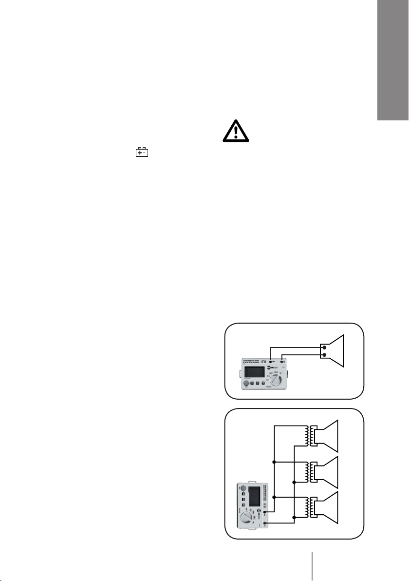
6Verica dell’impedenza di un altoparlante
Un altoparlante ha un’impedenza nominale solitamente
compresa tra 2 Ω e 16 Ω: selezionare tramite il
commutatore (5) il campo di misura 20 Ω.
7Verica di una linea a 100 V
Es. sono date le potenze (10 W, 50 W, 200 W) di tre
diffusori collegati ad una linea.
L’impedenza complessiva della linea (trascurando i
conduttori) è:
Z = V²
—
P= 100²
————————
(10+50+200) = 38,46Ω
a. Se l’impedenza misurata è all’incirca 38 Ω, non vi sono
problemi nella linea.
b. Se l’impedenza misurata è più bassa o più alta, vericare
eventuali:
– cortocircuiti accidentali (impedenza prossima allo 0);
– impostazioni errate nei selettori di potenza dei diffusori;
– linee non collegate opportunamente;
– difetti dei diffusori o dei relativi trasformatori.
10W
50W
200W

6
ITALIANO
MANUTENZIONE
1Sostituzione delle batterie
Se sul display appare il simbolo , occorre sostituire le batterie mettendone
delle nuove dello stesso tipo (6 x 1,5 V AA, alcaline).
Procedere come segue:
• spegnere l’impedenzimetro (commutatore FUNCTION su OFF) e togliere dallo
strumento i conduttori che fanno capo ai puntali;
• rimuovere le quattro viti centrali del coperchio posteriore (ma non le quattro viti
poste agli angoli) utilizzando un cacciavite, rimuovere il coperchio e sostituire le
batterie rispettando la polarità;
• rimontare il coperchio posteriore e ssarlo con le quattro viti.
2Pulizia e cura
Pulire periodicamente l’impedenzimetro usando un panno morbido asciutto; non
utilizzare sostanze abrasive o solventi.
Dopo aver terminato le misure da effettuare, riporre lo strumento sempre nella sua
custodia.
Se si prevede di non utilizzare l’impedenzimetro per periodi superiori ai 30 giorni,
rimuovere le batterie e riporle in un luogo separato.
Riparare lo strumento dalla polvere e soprattutto dall’acqua, che potrebbe
danneggiarlo e comportare un rischio di cortocircuito o pericolo per l’operatore
durante l’uso.
SPECIFICHE
1Conforme IEC-1010 (EN 61010); CAT III 100V
2Display: LCD con 3 ½ cifre (no a 2000) ed unità di misura
3Indicazione dati ritenuti (HOLD): simbolo sul display.
4Alimentazione: 9 V c.c. (6 batterie 1,5 V AA alcaline)
5Indicazione batterie scariche: simbolo sul display
6Dimensioni (l, h, p): 168 mm, 110 mm, 62 mm
7Peso: ca. 0,5 kg (batterie incluse)
8Accuratezza (data per un periodo di un anno dopo la calibrazione, alla temperatura di
18÷28°C, con umidità relativa inferiore al 75%):
± 2% + 2
(nella forma: ± % del valore misurato + valore della cifra meno signicativa)
9Frequenza del segnale di test: 1 kHz


8
ENGLISH
SAFETY NOTES
DO NOT CONNECT THIS IMPEDANCE TESTER TO ALIVE SYSTEMS!
1. Read the following safety notes carefully before using this impedance tester.
2. Use the impedance tester following the instructions on this user manual.
3. Rated environmental conditions:
a. Indoor use only
b. Pollution degree: 2 (IEC 60664-1)
c. Altitude: up to 2000 m (~ 6500 ft)
d. Relative humidity: 80% max.
e. Ambient temperature: 0 ÷ 40°C (32 ÷ 104 °F).
4. Observe the international electrical symbols listed below:
Double insulation
Caution! (Refer to this manual before using the tester).
5. Before switching the unit on, completely connect the tester to the load
(loudspeaker / line) to be measured with the two test leads.
6. To avoid an electric shock, do not touch any alive part of the system with your
body (hands / skin).
7. Do not use this tester near explosive gas, vapour or dust.
8. Disconnect the power (and discharge all high-voltage capacitors) before
connecting the test leads to the circuit to be measured. Make sure that the
object to be measured has no charge before applying the test leads.
INFORMATION ABOUT BATTERIES
1. Use (when possible) always new batteries to get the best performance.
2. Use alkaline batteries only.
3. Do NOT use old and new batteries at the same time.
4. Do NOT put together different models of batteries.
5. Do NOT use rechargeable batteries.
6. Do NOT attempt to charge non rechargeable batteries.
7. Verify the batteries’ polarity is correct (inserted properly, following the indication
on the relevant compartment).
8. Remove batteries when empty or in the case the unit will not be used for a long
time.
9. Do NOT short-circuit batteries (i.e. by connecting the 2 poles together with a
metallic wire).
10. Throw empty batteries into dedicated garbage can, according to the present
laws (of your country) about ecology and environment protection.

9
ENGLISH
RCF S.p.A. would like to thank you for purchasing this product, which has
been designed to guarantee reliability and high performance.
FEATURES
1Impedance measurement (frequency: 1 kHz) of a loudspeaker or a system.
2Three ranges (20 Ω, 200 Ω, 2000 Ω) that allow to test, for instance, home theatre
systems and / or commercial sound systems.
3Portable instrument operating with batteries.
4Low battery indication.
5Data hold function.
6Testing auto-off (1 kHz signal) after 20 seconds (but LOCK function).
7Auto power off after 15 minutes of non-use.
USE
1TEST button
It turns on/off the impedance test (when the tester is switched on).
After pressing the TEST button, the load impedance is tested (through a 1 kHz
signal) and the red LED (8) gets lit.
Press again to stop the impedance test (the red LED turns off).
About 20 seconds later (since the activation), the unit automatically quits the
impedance test (but the case the LOCK button has been pressed too).
2LOCK button
If the LOCK button is sequentially pressed after the TEST button, the unit will
not quit the impedance test mode automatically (after 20 seconds), but it will be
necessary to press the TEST button again (to turn the impedance test off).
3HOLD button
If pressed, the present reading is hold on the display (until the HOLD button is
pressed again). The display H letter indicates the HOLD mode.
4Display back light button If pressed, the display will be backlit for 10 seconds, in
order to allow the reading even in the darkness.
5FUNCTION selector
It turns the unit on/off and allows to choose the desired range (20 Ω, 200 Ω, 2000 Ω).
6COM
input for the black test lead.
7Ω
input for the red test lead.
8LED
(when lit) indicating the impedance test in progress.
5
6 7
8
1 2 3 4

10
ENGLISH
NOTES ABOUT THE TESTER USE
READ THE SAFETY NOTES BEFORE PROCEEDING.
1Make sure the system to be tested is not alive.
2If the symbol appears on the display, replace all batteries (by new ones).
3Connect both the test leads to the load (loudspeaker or line) to be tested.
Set the proper range (among 20 Ω, 200 Ω, 2000 Ω), by choosing the rst higher than
the expected value (if known) of the load to be tested, then press the TEST button
to start the impedance test.
4It is useful to get (/ make) a wiring drawing of the system that has to be tested.
5Power calculation of a constant voltage sound system.
P = V²
—
ZP = power; V = line voltage; Z = total load impedance
Example: on a 100 V system, if the load measured impedance is 200 Ω, the power
delivered by the amplier (connected to that line) is 50 W.
P = 100²
——
200 = 50W
It is possible to test the impedance up to 2 kΩ (corresponding to P = 5 W on 100 V
systems).
6Loudspeaker impedance test
A single loudspeaker has usually a nominal impedance
value in the range 2 ÷16 Ω: select the 20 Ω range by
means of the FUNCTION selector (5).
7100 V line impedance test
Example: 3 loudspeakers (with transformer) are
connected to the line and their power values are
respectively 10 W, 50 W, 200 W.
The line total impedance (assuming the wire impedance
negligible) is:
Z = V²
—
P= 100²
————————
(10+50+200) = 38,46Ω
a. If the measured impedance is about 38 Ω, the line
is OK.
b. If the measured impedance is signicantly lower
or higher, check for possible:
• accidental short-circuits (impedance close to 0);
• wrong loudspeaker power settings;
• wires wrongly connected;
• loudspeaker (or transformer) faults.
10W
50W
200W

11
ENGLISH
MAINTENANCE
1Battery replacement
If the symbol appears on the display, it is necessary to replace all batteries by
new ones of the same type (6 x 1.5 V AA, alkaline).
Proceed as following:
• Turn the impedance tester off (FUNCTION selector set to OFF) e take off the test
leads from the unit.
• Unscrew the four central screws of the rear cover (but not the four screws on the
corners) by using a screwdriver, remove the rear cover and replace the batteries
(note: pay attention to the polarity).
• Re-mount the rear cover and x it with the four screws.
2Cleaning and storage
Periodically wipe the impedance tester by using a soft dry cloth; do not use solvents
or abrasive substances to clean it.
After ending all impedance tests, always store the tester in its bag.
If the tester is not to be used for a period longer than 30 days, remove all batteries
and store them separately.
Keep this instrument far from dusty environments and water, which may damage
the tester or cause a short-circuit or be dangerous for the user.
SPECIFICATIONS
1Meets IEC-1010 (EN 61010); CAT III 100V
2Display: 3 ½ digit LCD (up to 2000) with unit
3Data HOLD indication: symbol appears on the display
4Power supply: 9 V dc (6 x 1.5 V battery AA alkaline)
5Low battery indication: the symbol appears on the display
6Dimensions (w, h, d): 168 mm, 110 mm, 62 mm
7Weight: about 0.5 kg (with batteries)
8Accuracy (specied for a period of a year after the calibration, at 18÷28°C (64÷82°F),
with relative humidity less than 75%):
± 2% + 2
(it takes the form of: ± % of reading + value of least signicant digit)
9Signal test frequency: 1 kHz

the rules of sound
RCF SpA: Via Raffaello, 13 - 42010 Reggio Emilia >Italy
tel. +39 0522 274411 - fax +39 0522 274484 - e-mail: rcfservice@rcf.it
Salvo eventuali errori ed omissioni.
RCF S.p.A. si riserva il diritto di apportare modifiche senza preavviso.
Except possible errors and omissions.
RCF S.p.A. reserves the right to make modifications without prior notice.
10307139/A
This manual suits for next models
1
Table of contents
Languages:
Popular Test Equipment manuals by other brands

Interacoustics
Interacoustics Affinity Compact Instructions for use

Continental Refrigerator
Continental Refrigerator Crypton CCP800 Operation manual

Hioki
Hioki 3560 instruction manual

Phenix Technologies
Phenix Technologies BK130 user manual

Hioki
Hioki 3550 instruction manual

PRESTON PRESSURE
PRESTON PRESSURE PS-525 Operation and maintenance manual

THORLABS
THORLABS PTR306 user guide

Ametek
Ametek NSG 4070C1 Quick start guide and safety instructions

Crane Electronics
Crane Electronics WM10K Operator's manual

Phenix Technologies
Phenix Technologies 600P Series user manual

AVYCON
AVYCON AIVO-70A4K user manual

Keysight Technologies
Keysight Technologies N7015A Quick Start and Accessories Guide