B&K 700 Use and care manual

CALIBRATION GUIDE – May 17th 2021
WWW.GARAGE1217.COM
WARNING:
Calibration requires knowledge of AC electrical systems, repair of said systems and restoration of said systems. If proper
safety measures are not taken, severe injury or death may result. Only a qualified electronics technician should upgrade
and calibrate their tube tester. Please – BE SAFE!
GARAGE1217.COM IS NOT RESPONSIBLE OR LIABLE FOR INJURY, PROPERTY LOSS OR DAMAGE AS THE RESULT OF ASSEMBLY OR USE OF THIS PARTS KIT OR CALIBRATION SET
B&K
700-707

Thank you for purchasing the our resistor calibration set. This set requires AC electronics and soldering
knowledge. Please make sure to follow the instructions outlined in this guide to properly calibrate your B&K 700 or
707 tube tester.
We HIGHLY recommend you restore and clean your tester electrically prior to calibration. Replacing resistors as
needed and replace all capacitors period – no exceptions. Below are details that we recommend:
- Start with a known working tester if possible or at least one that has not been butchered. If purchasing off ebay, make sure
to look for detailed photos, signs of water damage or corrosion on the face of the tester. And hopefully you will not find any
nasty surprises inside!
- Unplug your tester before cleaning!
- Make sure to clean all sockets and switches with Deoxit D5. Spray sockets and switches liberally. Let set for a few minutes
and then spray clean once again. When spraying and flushing out switch contacts, make sure press the switches several
times while flushing them out to insure the contacts are cleaned properly. With Rotary switches, rotate the switch while
cleaning. Do not forget to flush out the power switch, heater rotary switch and last, remove the fuse and flush out the inside
of the holder!
- We recommend spraying inside trimmers and potentiometers. Open cased wire wound potentiometers can be sprayed as
you move the potentiometer back and forth which helps clean the contacts
- We recommend you take loose and pry-open the sensitivity pot and spray clean while rotating
- Check to make sure all sockets hold a tube firmly. If loose, you can use a pick tool to gently re-position the female pins in
each socket if required or replace each socket if needed. Use socket savers on sockets you plan to use on a regular basis
- We recommend you use a variac and set AC line voltage to exactly 117V during calibration. Make sure large electronics
are not running in the house while calibrating such as air conditioners or electric heaters. They can alter line voltage several
volts when running, especially if your home or shop has older electrical.
- Test or have tested the 6BN8 and #83 tube. We highly recommend you replace the #83 tube with a solid state conversion.
#83 solid state / fused conversion directions located on the last page of this manual.
- We do recommend you solder the #55 lamp bulbs directly. While not absolutely required (these testers have worked fine
for ages not doing this) it is a very smart thing to do. At minimum, clean the bulb and socket with deoxit. Then clean again
and check every 5-6 months. ONLY USE VINTAGE BRASS BASE BULBS! DO NOT USE MODERN #55 BULBS, SIGNAL
VOLTAGE WILL LIKELY NOT DIAL IN IF YOU USE A MODERN EQUIVILANT!
- We recommend re-touching and re-flowing all solder joints one at a time, adding in a small amount of fresh no-clean solder
or quality solder of your choice. This is not required but can resolve a lot of hidden issues
B&K
700-707
Calibration

B&K
700-707
Calibration
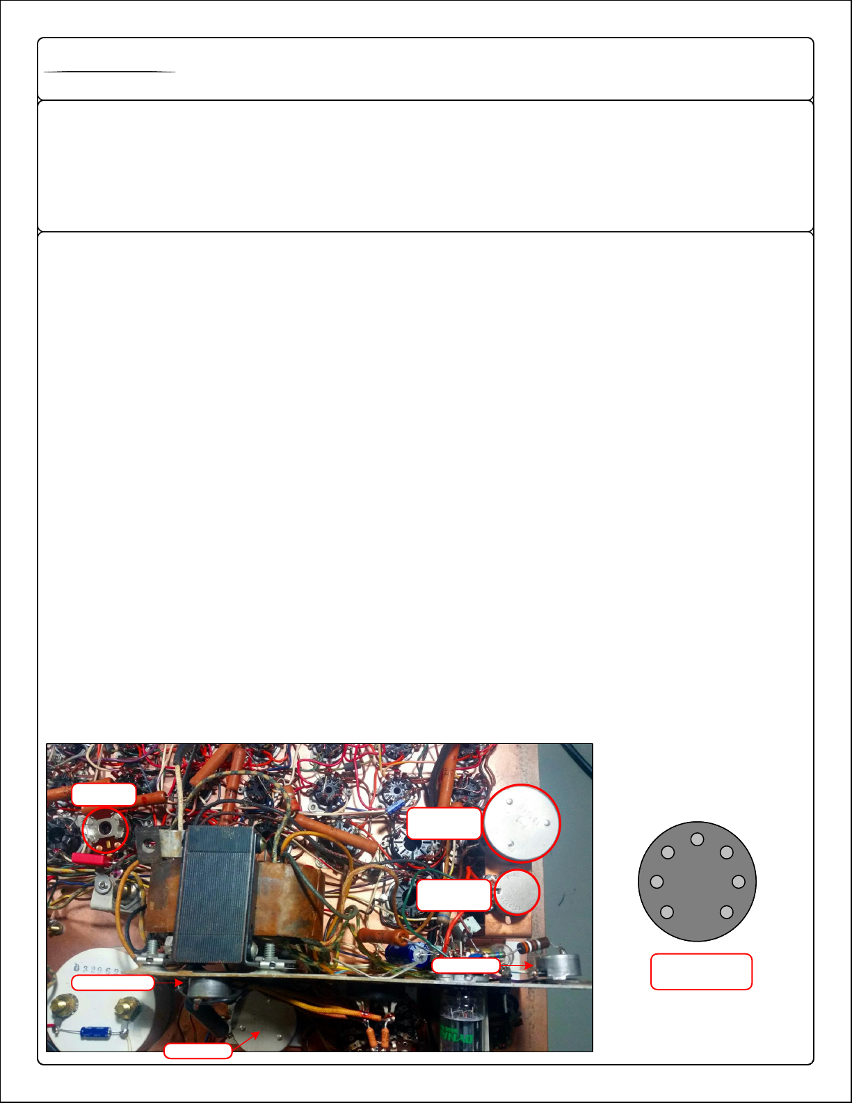
SENSITIVITY POT
R5 BRIDGE BALANCE
R16 / SHORTS /
SOCKET 30
R17
GRID EMISSIONS
SOCKET 33
R20
SIGNAL VOLTAGE
SOCKET 25
R11 DC BIAS
SENSITIVITY POT
R5 BRIDGE BALANCE
R16 / SHORTS /
SOCKET 30
R17
GRID EMISSIONS
SOCKET 33
R20
SIGNAL VOLTAGE
SOCKET 25
R11 DC BIAS
Locations of pots / trimmers to be adjusted. Several are accessed from the front panel of the tester through the
center of certain tube sockets. If a socket number is indicated, access from the front panel.
The size of certain potentiometers such as R20 changed over the years. Do not panic if photos do not match
exactly. It is the location of the unit that is important!
Socket #1 is used with our calibration set. It is important to understand the tube socket pinout as it is not counted
in a standard clockwise rotation. When looking at a tube socket from the top, pin numbers go counter-clockwise as
shown below
7
6
5
4
3
2
17
6
5
4
3
2
1
SOCKET 1 PINOUT
(TOP VIEW)
B&K
700-707
Calibration
Calibration Steps:
Make sure the “Circuit Transfer” button on the front panel is in the UP position before starting.
Be sure to use insulated screwdrivers during adjustment and pay attention to hand placement when the tester is out of its
case. Electrocution or death is VERY possible if you are not careful! NEVER touch the underside of the tester with both
hands while the unit is plugged in – EVER. Do not touch resistor metal leads while testing – EVER.
Step 1 / Shorts Adjustment:
Insert the gold pins of the provided 1 meg resistor into socket 1 / pins 2 and 4. With the shorts button depressed, Adjust R16
until the shorts lamp just barely illuminates. Once the 1 meg resistor is removed and the shorts button is pressed again, the
light should not come on.
Step 2 / Grid Emissions Sensitivity Adjustment:
Insert the gold pins of the provided 20meg resistor into socket 1 / pins 1 and 7. Adjust R17 with the grid emissions button
depressed so that the meter reads 20.
Step 3 / Signal Voltage Adjustment:
You will need a DMM or DVOM for this step. Set your meter to autorange AC.Insert the gold pin of the 1uF capacitor into
socket 1 / pin 1. Then, insert the gold pin of the metal hoop carefully into socket 1 / pin 2 (this is a very tight fit). Press and
hold test button 1 and adjust R20 to dial in 1.5V AC on your DMM or DVOM.
Step 4 / DC Bias Adjustment:
You will need a DMM or DVOM for this step. Set your meter to autorange DC. Connect your DMM or DVOM via clips to the
backside of socket 1 / pin 1 and 2. Pay attention to which pin is which when looking at the tester from the back side! Press
and hold test button 1 and adjust R11 to -2.5V DC.
Step 5 / Bridge Balance Adjustment:
Prior to adjusting balance, make sure your meter has been mechanically zeroed. With the tester at rest, meter facing up,
adjust the small flat plastic screw at the base of the meters needle so that the meter rests exactly at 0. Next, insert the gold
pins of the provided 10K resistor into socket 1 / pins 2 and 5. Set sensitivity control to maximum / 100. Press and hold test
button 1 and adjust R5 until the meter reads zero electrically.
Recommended or Required to have available:
- Magnifying glass (recommended but not required)
- Thick Rubber Gloves can help prevent electrocution (recommended but not required)
- Digital Multi Meter (DMM or DVOM)
- #2 Phillips screwdriver (insulated)
- Full set of calibration resistors & capacitor
- A quality digital multimeter with spring loaded IC hook leads
7
6
543
2
17
6
543
2
1
SENSITIVITY POT
R5 BRIDGE BALANCE
R16 / SHORTS /
SOCKET 30
R17
GRID EMISSIONS
SOCKET 33
R20
SIGNAL VOLTAGE
SOCKET 25
R11 DC BIAS
SENSITIVITY POT
R5 BRIDGE BALANCE
R16 / SHORTS /
SOCKET 30
R17
GRID EMISSIONS
SOCKET 33
R20
SIGNAL VOLTAGE
SOCKET 25
R11 DC BIAS SOCKET 1 PINOUT
(TOP VIEW)
B&K
700-707
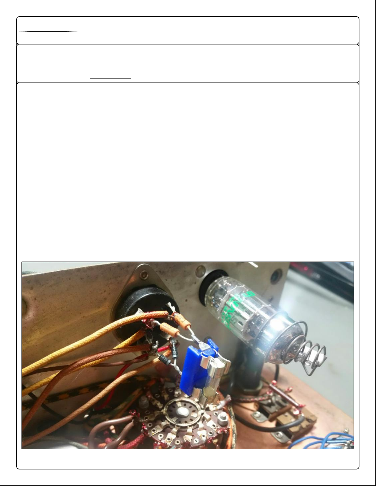
SS #83
CONVERSION
Converting the #83 tube to Solid State using 1N4007 Diodes / Fused for protection (the easy way)
Converting the #83 tube to solid state is a pretty straightforward and easy affair. Some try to make it sound like
rocket science but it is not. With the right components, you can solder a fused assembly to the backside of the #83
socket with ease. The specified vishay resistors combined with the 1N4007 diodes (twisted together as shown)
provide a solid mount for the fuse holder that will not cause issues later. This mod is a MUST. Drastically increases
reliability AND protects your transformer if things go wrong!
Step 1: Remove the big ugly #83 tube from its socket
Step 2: Solder the anode (black end) of each diode to the wires closest to the heater selection rotary switch. These should
be the SMALL diameter socket pins on the #83 socket. I have never seen a socket mounted upside-down but it is possible
so pay attention!
Step 3: Solder each 10R resistor to the top two pins furthest away from the heater selection rotary switch.
Step 4: Twist the diode leads together and clip off excess. Then, do the same to the resistor leads.
Step 5: Solder the fuse assembly as shown. Connecting the diode pair to the resistor pair. Make sure solder flows into the
twisted part of the diode and resistor leads. This will provide a very solid structure for the SS conversion.
That’s it! DONE!
Recommended Parts for the #83 SS conversion:
- 2qty Diodes P/N: 1N4007
- 2qty Vishay CPFseries 10Rresistors P/N: CPF310R000FEE14
- 1qty 200mA fast blow fuse P/N: BK/GMA-200-R
- 1qty 5x20mm PCB fuse holder P/N: 64600001003
This manual suits for next models
1
Table of contents
Other B&K Test Equipment manuals


