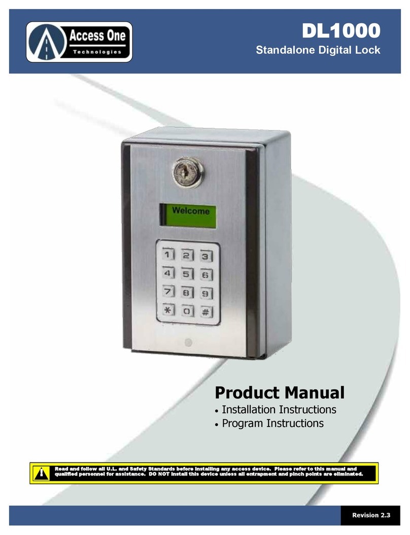
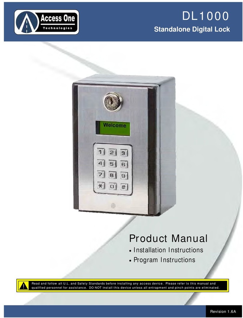
DL1000
Quick Reference Guide
DL1000, Rev 1.6 Page 1
OVERVIEW:
The DL1000 allows simple keyless access control
through automatic gates and pedestrian doors. It
includes a 7-day plus time clock for code and relay
control. An event input and two exit inputs are also
available. Two relays can be used for dual
applications..
Download the DL1000 Installation & Program
Manual at www.AccessOneTechnologies.com
BASIC WIRING OVERVIEW:
The DL1000 has two relays to control several types of
devices. To connect the DL1000 for basic use:
1. Connect a 12-24VAC/VDC power source to the Power
Terminal.
2. Connect the activation device to the Relay 1 or Relay 2
inputs. There are NO, NC, and C inputs.
3. Connect bypass devices such as Postal Locks to the
Exit 1 or Exit 2 inputs.
4. Connect Event devices such as loop detectors, wireless
detectors to the Event input for controlled access.
ADD SIMPLE ENTRY CODE:
Simple entry codes may be entered to speed up
programming. When a simple code is entered, it will
use the default settings listed below. To program a
simple entry code:
1. Press and hold for 3 seconds.
2. Enter PAC (Default=000000)
3. Enter to add an entry code.
4. Enter code then
5. Repeat step 4 for more codes.
6. Press to exit.
Note:
To edit entry code features, use # for each setting to
accept the default or make the change at each step.
DELETE SINGLE ENTRY CODES:
Entry codes may be deleted individually or as a block.
To delete individual entry codes:
1. Press and hold for 3 seconds.
2. Enter PAC (PROGRAM)
3. Enter to add an entry code.
4. Enter code
5. Press to delete code
6. Press to confirm
7. Repeat step 4 for more codes.
8. Press to exit.
ENTRY CODE DEFAULTS:
*
1 #
# 0
** #
*
*
1 #
2 #
#
**#
Setting Default
Relay 1 Function Momentary
Relay 1 Event Control Off
Relay 1 Time Control Off
Relay 2 Function None
Relay 2 Event Control Off
Relay 2 Time Control Off
Flash Code Uses 99 (Unlimited)
Do Not Disturb Off
Mount the system at least 10 feet away from a
vehicular gate and its travel.
!
DO NOT mount operating devices accessible
through the gate or in between gate and wall.
!
Mag
Lock
Power
Electric
Strike
Power
1 2 3 4 5 6
12-24 AC/DC
C Ev Ex1 Ex2
DL1000
Quick Reference Guide
DL1000, Rev 1.6 Page 2
ADD/EDIT CUSTOM ENTRY CODES:
Individual entry codes may be customized to activate
the relays differently, use the Event input and/or the
time clock to control access, and set the number of
uses it is valid for. To program a custom code (Note:
Pressing # at each step accepts default setting):
1. Press and hold *for 3 seconds
2. Enter XXXXXX program access code (PAC)
3. Enter 1 # for entry code programming
4. Enter xxxxxx for entry code
5. Press #for new code, 1 # to edit existing code
6. Enter x # for Relay 1 function (See relay chart)
7. Enter x # for Relay 1 Event control (1=Off, 2=On)
8. Enter x # for Relay 1 time control (1=Off, 2=On) If off,
skip to step 15.
9. Enter xx xx xx # for start date (mm/dd/yy)
10. Enter xx xx xx # for end date (mm/dd/yy) #=no end date
11. Enter xxxxxxx # for active days of week (1=Sun, #=All)
12. Enter xx xx xx # for start time (hh:mm:ss)
13. Enter x # for start AM/PM. (1=AM, 2=PM)
14. Enter xx xx xx # for end time (hh:mm:ss)
15. Enter x # for end AM/PM. (1=AM, 2=PM)
16. Enter x # for Relay 2 function (See relay chart)
17. Enter x # for Relay 2 Event control (1=Off, 2=On)
18. Enter x # for Relay 2 time control (1=Off, 2=On) If off,
skip to step 25.
19. Enter xx xx xx # for start date (mm/dd/yy)
20. Enter xx xx xx # for end date (mm/dd/yy) #=no end date
21. Enter xxxxxxx # for active days of week (1=Sun, #=All)
22. Enter xx xx xx # for start time (hh:mm:ss)
23. Enter x # for start AM/PM. (1=AM, 2=PM)
24. Enter xx xx xx # for end time (hh:mm:ss)
25. Enter x # for end AM/PM. (1=AM, 2=PM)
26. Enter xx # for Flash Code uses. (99=Unlimited)
27. Repeat steps 4 - 26 for additional codes
28. Press * * # to exit
RELAY FUNCTION & EVENT CONTROL CHART:
TIME CLOCK PROGRAMMING:
The DL1000 has a built-in 7-Day Plus time clock for
time control of individual codes and relay open
schedules. To set the time on the clock:
1. Press and hold for 3 seconds
2. Enter PAC (PROGRAM)
3. Enter for time clock settings
4. Enter date then
5. Enter day of week then (1=SUN)
6. Enter time then
7. Enter AM/PM then (1=AM, 2=PM)
8. CLOCK SET. Press to exit.
RELAY TIME SCHEDULE PROGRAMMING:
Relay Time Schedules can be used to open a gate,
hold a gate open for a set time/date, and/or release
the gate at a set time/date. To program a schedule:
1. Press and hold *for 3 seconds
2. Enter XXXXXX program access code (PAC)
3. Enter 7 # for relay options
4. Enter 4 # for relay schedules
5. Enter x x for schedule number. (01-99 schedules)
6. Enter #for new schedule, 1 # to edit existing schedule
7. Enter x # for Relay 1 function (See relay chart)
8. Enter x # for Relay 1 Event control (1=Off, 2=On)
9. Enter xx xx xx # for start date (mm/dd/yy)
10. Enter xx xx xx # for end date (mm/dd/yy) #=no end date
11. Enter xxxxxxx # for active days of week (1=Sun, #=All)
12. Enter xx xx xx # for start time (hh:mm:ss)
13. Enter x # for start AM/PM. (1=AM, 2=PM)
14. Enter xx xx xx # for end time (hh:mm:ss)
15. Enter x # for end AM/PM. (1=AM, 2=PM)
16. Enter x # for Relay 2 function (See relay chart)
17. Enter x # for Relay 2 Event control (1=Off, 2=On)
18. Enter xx xx xx # for start date (mm/dd/yy)
19. Enter xx xx xx # for end date (mm/dd/yy) #=no end date
20. Enter xxxxxxx # for active days of week (1=Sun, #=All)
21. Enter xx xx xx # for start time (hh:mm:ss)
22. Enter x # for start AM/PM. (1=AM, 2=PM)
23. Enter xx xx xx # for end time (hh:mm:ss)
24. Enter x # for end AM/PM. (1=AM, 2=PM)
25. Repeat steps 5 - 24 for additional codes
26. Press * * # to exit
Setting Relay Function
1 None
2 Momentary (Default)
3 Latch
4 Unlatch
5 Latch Timeout
6 Toggle
Setting Event Control Function
1 Off (Default)
2 On
*
3 #
m m d d y y #
#
h h m m s s #
#
**#


