RCRCM Strega User manual

[Type the document
title]
[Type the document subtitle]
[Type the abstract of the document here. The abstract is
typically a short summary of the contents of the document.
Type the abstract of the document here. The abstract is
typically a short summary of the contents of the
document.]
Paul
[Pick the date]
RCRCM Strega
Manual
by Paul Vesely

2
Contents of the Strega Manual
Introduction......................................................................................................................................................... 2
Materials needed................................................................................................................................................. 3
Strega-Kit......................................................................................................................................................... 3
Additional materials required......................................................................................................................... 3
A few added and some replaced parts............................................................................................................4
Preparations and assembly of parts:................................................................................................................... 4
Sanding the sealing lips................................................................................................................................... 4
Installation of control horns in the wings....................................................................................................... 5
Installation of the wing servos........................................................................................................................ 7
(Making and) mounting the servo board...................................................................................................... 16
V-Tail linkage................................................................................................................................................. 18
Ballast tube....................................................................................................................................................19
Setup of the plane.............................................................................................................................................. 21
Flying Strega...................................................................................................................................................... 23
Introduction
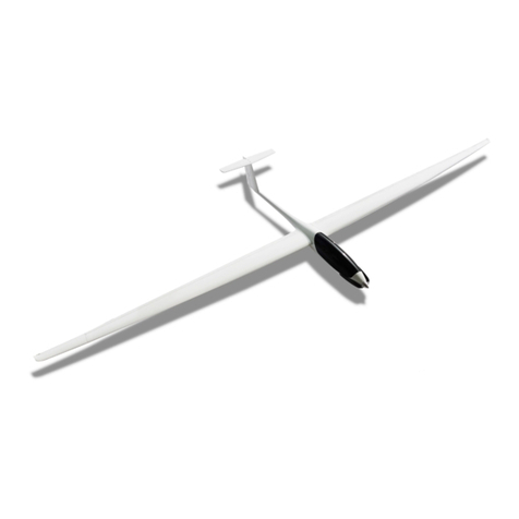
The RC glider Strega from RCRCM is a full on F3F/F3B sports model. It is ideal for the ambitioned RC
amateur pilot who wants a high end all-round glider that features excellent thermal flying- but also
speed flying- capabilities. In addition, the Strega cuts through hard transitions smoothly and will also
promptly follow your commands through basic aerobatic maneuvers.
I prepared this assembly guide for the medium experienced craftsman. Therefore, I have
described all assembly steps that I deem critical for proper function of the plane. Knowledge of
standard techniques such as use of epoxy resin, soldering cables and plugs, as well as
preparation/choice of batteries and RC equipment, is required. In a few cases I used materials that
are not supplied with the kit. There, more detailed explanations- as well as the reasons for the
changes- are given. I actually really enjoyed the building process of the Strega and, I wish you a lot of
fun building it yourself! At the end of this guide there will also be a section on the RC-setup of the
plane and on flying it.

3
Materials needed
Strega-Kit
You can order the kit via https://www.rcrcm.com. Once the kit arrives you should have a good work
bench covered with cloth (for plane surface protection) at hand. First lay out all parts. Here is what
you should find, see figure 1.
Figure 1. List of Strega kit parts: (a)Wings; (b)accessories [see insert on the upper left; 16 clevises, 8
threaded rods, 4 control horns]; (c)wing servo mounts; (d)wing servo-bay covers; (e)ballast tube; (f)fuselage
servo tray; (g)carbon push-rods; (h)tail piece; (i)fuselage; (j)V-tail joiners; (k)two piece V-tail; (l)wing joiner;
(m)canopy.
Additional materials required
Servos: I used two DS215MG V3 in the fuselage and four DS225MG as wing servos.
Receiver: I used a R6208SB from Futaba, but many different ones will do just fine.
Battery: You can use many types of NiMH or lithium technology based batteries, which are readily
available in several RC shops. There is no need to go for high discharge C. Just make sure the voltage
fits your RC system and you have at least 2Ah capacity, offering a good amount of flying time. My
personal choice were two Samsung ICR18650 LiIo cells, 2850 mAh capacity, 2C discharge capability
connected in series and with self soldered balancer and connector cable system. LiIo cells are
probably one of the cheapest & best systems in terms of space requirements, weight, performance
and price.
a
m
i
h
f
k
e
l
j
c
d
g
b
b

4
Ballast: It is best to order the Strega ballast set together with the kit via https://www.rcrcm.com. For
the fixed mounted nose ballast I suggest to use lead shots, widely available in RC stores. Get at least
150g.
Wiring Harness: Probably available at RCRCM in future. Even so, mine is self soldered. To do this, get
about 4m three pole 0,34 qmm servo cable, 2 green multiplex plugs for wing connection and about
10 connector plugs for the RC system of your choice.
Miscellaneous: You will need a good toolset, soldering equipment, UHU Endfest epoxy (which will
harden to “bullet proof quality” over night), 5 min Epoxy, super glue (cyan acrylate based, extra fast
hardening glue), shrinking tubes of various sizes, e.t.c. e.t.c…. in other words a normally equipped RC
assembly work area.
A few added and some replaced parts
You can assemble Strega nicely using only materials mentioned above here. For personal preference
and for best performance however, I added a few things and I choose to replace some original parts.
Ballast tube mount: I desigend a rib for the fuselage and cut it from plywood, see figure 18.
Clevises (Fork heads): The original clevises were substituted by conventional ones (widely available
in RC stores) for better performance and zero tolerance assembly.
Carbon rods: The ones seen in figure 17 (upper left), were used instead of the supplied metal
threaded rods. Again carbon rods are widely available in most RC shops, probably stiffer but sure
lighter and better for tolerance free fork head mounting, than the original metal rods.
Servo tray: To gain a little space in the fuselage I cut a newly designed servo tray for parallel servo
mounting from 3mm plywood and reinforced it on top and bottom with one layer glass fiber
laminate, see figure 16.
Preparations and assembly of parts:
Before you start, spread a fleece blanket over your work bench and apply masking tape onto the
critical parts of your plane, to protect the delicate high gloss surface.
Sanding the sealing lips
The sealing lips of all control surfaces need to be bevelled to ensure that they won’t “catch wing”.
This is most important for the flaperons(flaps) due to their great deflection level during use as
airbrakes. See figure 2.

5
Figure 2. Taper the control surface sealing lips: First cover your working table with a soft cloth, such as a
fleece blanket to protect the wing surfaces. Next, apply masking tape onto the respective wing and control
surface (left panel). Now, use a sanding block to bevel the sealing lips carefully. Be careful to keep the “angle
of attack” constant over the whole length of the sealing lip, as seen in the middle panel. This will help to
generate a pointed leading edge (see right panel, red box) that won’t catch the wing surface, even after
coming back in from maximum deflection.
Installation of control horns in the wings
This is an especially important task because it will critically determine the function of the control
surfaces. Here, I describe the use of a “classic” cross-wise linkage system for ailerons (ails) and flaps.
Therefore, drill holes through the wing back shear web, the flap- and ail- shear webs. See figure 3.
Figure 3. Drill holes for control horn installation: You can use a round file to file a whole into the wing back
shear web exactly below the pushrod exit hoods (left panel). Alternatively, you can also use a small electric
drill with a rotary bit (middle panel). In this case however, be careful not to break through the wingskin. If
you place one finger underneath it you will feel the vibrations once you get critically close to the surface.
The flap and ail shear webs have to be treated the same way. In the end they should all look like in the right
panel.
Before you can glue the control horns into the holes of the flap and ail shear webs, they have to be
properly prepared. First, using a drill, you will need to carefully adjust them so that the clevises will
perfectly fit in the respective holes. Next, impregnate them with UHU endfest. See figure 4.

6
Figure 4. Prepare the control horns for flaps and ails. Measure the diameter of the little perpendicular rod
inside the clevises. Now choose a drill with a diameter slightly smaller than what you just measured and
carefully drill through the clevis-attachement hole of each control horn (upper left). Now the clevises can be
attached (upper right). Closing the clevises should not go easily, and once closed, it is totally fine if it is hard
to move each control horn within the respective clevis. This way tolerance will be at a minimum and the
movement capacity will be fine, eventually. Now you want to mix UHU endfest and distribute a medium
thick film of it on each of the control horns (lower panels). Be careful not to add resin onto the clevises.
However, if that happens you will still be able to break it later (before the resin is fully cured).
Subsequently glue the readily prepared control horns into the holes that were previously prepared
in the the flaps’ and the ails’ shear webs. The flaps will need 70-80˚ downward/and only a few mm
upward travel, whereas the ails will need over 10 mm upward and a little less than that downward
travel. Therefore, the positioning for flap and ail control horns is different. I have prepared a scheme
and one should exactly follow the scheme when fixing the horns with the slow curing extra strong
UHU endfest. See figure 5.

7
Figure 5. Mount the control horns: it is best to fix the control surfaces in a 90˚ angle to the wing using
masking tape, first. Now have a look at the upper panel. This describes exactly how to fix the control horns
respective to the hinge of each control surface. Note the different positioning for flaps and ails. To glue the
horns in you can use the same epoxy resin that was prepared for impregnating them. Just add some cotton
flakes or microballoons for higher viscosity. Let the thickened resin drop into the holes (that you prepared)
in the flaps’ and ails’ shear webs (lower left panel). Subsequently insert the control horns exactly as
described (in the upper panel) using a caliper for measuring their positions. Essentially you can stick the
control horn into the embedded epoxy, adjust it and fix it with tape (lower right panel). However, and this is
very important, come back about 2-4 hours later, when the epoxy is sticky but not hard, and re-adjust the
position to a perfect fit. The slow curing type of epoxy will allow for enough time (several hours) for
adjustment. Eventually, after over night curing you can remove the positioning tape and the clevises.
Installation of the wing servos
The cross-wise linkage system demands that the servo control horns are as short as possible.
Therefore, extra holes have to be drilled in the horns and the clevises need to be tuned. Figure 6 will
guide you through the preparation of servo horns and clevises for the wing servos.

8
Figure 6. Prepare the servo horns and clevises for the wing servos. First drill a hole through the servo horns
(for choice of drill see figure 4) 2,5mm outside the servo horn base (upper panels). The clevises will need to
be milled on the bottom side to allow for full movement respective to the servo horn shaft (middle panel
and lower left panel). Once that is done the clevis allows for full movement when mounted on the servo
horn (lower right).
Once the servo horns and clevises are readily prepared the servo frames need to be adjusted for
perfic fit and test fitted in the servo bays. See, figure 7.

9
Figure 7. Prepare the servo frames: Mill down the servo horn side of each of the four servo frames (left
panel) to allow for full movement of the servo horns (middle). Check if full range of motion is allowed for
(middle). Test fit the servos in the servo bays (right). The front edge of the servo should be aligned with the
front edge of the servo bay. Fiddle in the pushrods through the holes in the shear webs and connect them to
the servo control horns in upright position. The servo should now be straight aligned and the pushrods need
to move freely while pointing exactly towards the wing control horns. If that is given mark the servo position
(right).
Next, you want to fix the wing servo frames in the marked positions using slow curing UHU endfest
epoxy. It is best to do this with the servos attached to the frames to find the exact positions.
Importantly, you will need to protect the servos from the epoxy to ensure that they are not getting
stuck for good in the wings. See figure 8.

10
Figure 8. Fix the servo frames in the wings: First, wrap each servo with saran wrap (upper left). Next, briefly
sand servo bays and bottom of servo frames and push each (saran wrapped) servo into its respective servo
frame (upper right). Now mix the endfest epoxy, add some cotton flakes (or microballoons) for
thixotrophing it and smear it into the fine sanded servo bays and onto the bottom of the servo frames. Bring
the frames with the servos into the marked position in the wings (lower left). A nice trick for tight
attachment of the frames is to put water filled plastic bags on top of them (lower right). This ensures even
weight distribution and is simple. Putting metal weights on top of servos however, is good too.
As soon as the servo frames are fixed in the respective wing servo bays you can mount the linkage
systems for flaps and ails. Be aware that the flaps will need about 80˚ negative throw and only a little
positive throw; while the ails need roughly the same positve- and negative- deflections. Figure 9 will
describe how to achieve these settings.

11
Figure 9. Adjust the ail and flap linkage systems: Fix the wing servos with the appropriate screws.
Therefore, you first might need to grind off a little from the surrounding wing (upper left & right). Next
screw the clevises onto the supplied metal threaded rods to create pushrods (upper middle panel). Now
they need to be adjusted. Flaps: Connect the respective servo to your receiver(+battery). Switch on your
transmitter and choose a “clean channel” by creating a “new model” setup without any pre-settings. Install
the servo horn in a 30˚ forward angle (upper right). This will allow for extreme positive (downward)
movement of the flap, as needed for airbrake. Next, fiddle in the respective pushrod through the hole in the
shear web and connect to the servo horn (upper right). Remember that one clevis has a grinded side, which
needs to face the servo horn base. Now, adjust the pushrod’s length so that upon connection to the control
horn (middle, right) the flap is in strak (in perfect alignment with the normal profile). Go about it the exact
same way for the ails, except that you mount the servo horn in a straight position, because here pretty much
equal +/- movements can be desired. Test both flaps and ails. Flaps need a maximum deflection of about 30-
45˚ +/- (lower panels) and flaps around 80˚positive and only 30˚ negativ. Finally, make sure again flaps and
ails are in strak when connected to a clean channel. Finally, de-mount the push-rods as well as the servos
but keep the adjustments conserved.
As soon as your wing servos are mounted and you have adjusted the pushrods and sucessfully tested
the deflection levels of flaps and ails, its time solder the pushrods. This will help you to achieve
minimum tolerances. The next step also involves soldering. Prepare the wing cable trees and fiddle
them into the wings. Both tasks are explained in figure 10.

12
Figure 10. Soldering wing -pushrods and –cable trees: To ensure a tolerance free fit of your flap and ail
linkage systems it is advisable to permanently fix both clevises on either side of the threaded rod by using
super glue or, as shown here by soldering them (upper left). For the end result, see (upper right). While
you’re at soldering, I suggest to also prepare the wing cable trees. A conventional 3 x 0,34 qmm diameter
twisted servo cable will do perfectly for this job. Solder each of the four servos with a piece of cable long
enough to protrude 10cm out of the wing at the wing base. I simply cut the cables of the servos sequentially,
interspaced by 3cm and vice versa for the connector cables. This way I can solder them (lower left) and
subsequently cover them using just one heat shrink tubing (yellow, on top of lower right panel). Next, fiddle
any type of cord from the wing base to the servo bays using e.g. on fo the provided carbon tubes (figure 1g)
and a piece of tape to fix the cord to the tube. Next, you can knot the readily soldered servo cables to the
cord and pull each one through the wing.
Both, the flaps’ as well as the ails’ servo connector cables now need to be soldered to plugs to allow
for connetion to the fuselage. Green multiplex plugs are well suited for this. See figure 11.

13
Figure 11. Mount the wing sided multiplex plugs: A little tuning of the servo cable outlets is needed to
ensure that the plugs can move freely in there (upper left). Solder the cables of both wing servos onto the
male plug (upper right). Next, wrap some transparent tape around the plug and cables and fill the resultant
cavity with 5min epoxy (lower left). After the epoxy has hardened you have got a perfetly isolated and
protected connetion (lower middle), and can be freely moved around in the cable outlet (lower right).
If cable trees are mounted and plugs are connected at the wing bases it is time to fix the servos in
the servo bays. This step is really easy because everything that is needed is readily prepared. See
figure 12.

14
Figure 12. Mount the wing servo, in their respective servo bays, in the readily prepared servo frames (upper
left). Servo arms shoud still be in the right positions as prepard under figure 9, above. Therefore, you can
also easily attach the linkage system at the servo horns and at the control horns. Again, one of the two
clevises on each pushrod has a grinded side, which needs to face the servo horn base, to allow for full
movement . Once each servo is propely installed and connected (upper right), the supplied servo covers will
fit easily on top of them (upper right). However, for better aerodynamics you can substitute them for plain
plastic plates that were cut to size, accordingly. Fix them with transparent tape, as usual. No structural
support is provided or needed by any of those servo covers. I personally used transparent plastic plates so
that you can see the servo below (lower image).
If that is done the wings are all ready to go! Now prepare the fuselage side of the wing servo cable
connectors. Figure 13 shows readily assembled Strega wings.

15
Figure 13. Readily assembled Strega wings. Test for proper function of the wing RC system as soon as the
fuselage sided wing servo plugs and corresponding receiver cables are installed.
Now that the wings are all finished the RC equipment as well as the ballast tube need to be installed
in the fuselage. Figure 14 shows how to install the fuselage sided wing servo plugs and the
corresponding receiver cable installation.

16
Figure 14.: Mount the fuselage sided multiplex plugs: Solder the receiver cables to the plugs as described
for the wing sided ones (figure 11). This time seal them with very little epoxy to achieve a short length
because there is little space in the fuselage (upper left). Additionally, cover in shrink tubeing for extra
protection (upper right). Before you start your work on the fuselage, completely protect it by masking tape.
Now adjust the fuselage sided plug opening with a file so that the plug shows a snug fit in there. Use 5 min
epoxy to fix the plugs in the fuselage. Smear a thick layer of the epoxy onto each plug and each opening.
Wait until the epoxy is semi cured, insert plugs into opening and hold with pliers until epoxy has cured
enough to release the plug (lower left). This will take a minute or so if you waited long enough before. Of
course you can also prepare a holder template and use this to fix the plug until epoxy is cured. End result
(lower right).
(Making and) mounting the servo board
The Strega fuselage is quite narrow, which helps to achieve excellent aerodynamics. So, before you
start with any RC equipment installation procedures you need to know the kind of battery, receiver,
servos and switch e.t.c., e.t.c. that you will want to use. Put it all into the fuselage and keep in mind
that there still needs to be space behind the servo board for ballast tube mounting and in front of all
RC gear for the nose ballast. In my case I used the following lineout, see figure 15.

17
Figure 15. Lineout for the RC gear in the fuselage: Before you buy the RC gear think about the way you want
to install it in the fuselage. I found that parallel installment of two KST 215 servos in conjuntion with 2
lithium ion batteries placed in front of the servos gives me plenty of space in the fuselage for all other RC
gear needed, see figure. This figure is therefore, plainly meant as one example how the RC gear could be
placed in the fuselage. Note, the receiver sits on top of the battery. Moreover, be sure to keep enough
distance between servo board and ballast tube so that you can firstly, still mount the tube and secondly,
load and unload the ballast conveniently.
Once you have estimated the perfect positioning for your RC gear including the servos, design your
servo board and laminate it into the fuselage, see figure 16.

18
Figure 16. The servo board: To save precious space in the fuselage cut out your own servo board from 4 mm
plywood using the supplied one as rough template (upper left). I used 3mm plywood and laminated one
layer of 80g glass on top and bottom. Make sure the board fits perfetly but thightly in the fuselage at your
desired position. The servos should be mounted in the board when you test fit it in the fuselage. Thereby,
you can estimate how deep in the fuselage you may mount it. Mark servo board positioning in fuselage
(upper right). Cover outside of fuselage with masking tape to protect from epoxy. Now mix UHU Endfest
epoxy and smear a thick layer into the fuselage where the board should sit (middle left). The servo board
itself is also covered by masking tape. Just leave about half a cm blank on the sides for good attachement to
fuselage by the epoxy. Smear epoxy on bottom and top of the sides of the board and press it into marked
position in the fuselage (middle right). After about 4-6h of curing at room temperature, when the epoxy has
hardened but isn’t yet bullet proof, remove masking tape and if there are any unwanted epoxy residues cut
off with stanley knife (see lower images).
V-Tail linkage
The V-Tail linkage installation is really a straight forward process. It is no different from what you
would do for most RC planes, except that the linkage system here is made up entirely from carbon

19
rods with clevises permanently connected, to get a close to zero tolerance linkage system. Figure 17
will guide you through that process.
Figure 17. V-Tail linkage: Upper left. Use the long carbon rods that are delivered with the kit (figure 1g).
Fiddle them into the fuselage. Servo horns need to be in 90˚ position to servos and V-tail control surfaces in
strak. Now mark each rod 4 cm in front of the respective V-tail linkage horn and 4cm behind the servo horn.
Take them out of the fuselage and cut at marks. Instead of the supplied threaded rods (figure 1b), I suggest
to use 1,5 mm carbon rods for the connection of the clevises. Cut the 1,5mm rods to four 10cm pieces
(upper left) and laminate those 7-8 cm deep into both sides of the thick carbon rods using UHU endfest. Let
cure over night. In the meanwhile, trim the clevises as seen for wing servo clevises in figure 6. Once epoxy
has cured, the clevises can be screwed onto the rods with force. To make it easier, you can grind off some
material from the end of the rods using glass paper. Now, adjust clevis positions so that the V-tail control
surfaces are perfectly in strak when the servos are in 90˚ positions (upper right). Permanently attach
clevises using cyanacrylacetate super glue (lower images). As soon as hardened you can mount the ready
made pushrods in the fuselage and you will be happy that there is close to zero tolerance on the V-tail.
Ballast tube
The wing as well as the fuselage servos and linkages are all mounted, so I suggest to install the
ballast tube in the fuselage. In figure 18 I describe how to mount it exactly in the CG.

20
Figure 18. Mount the ballast tube in the CG: The rib needed for ballast tube mount in the fuselage is shown
(upper left). On the second (from left) upper panel you see how the ballast tube and the wing servo cables
fit through the ballast tube rib. To permanently mount the ballast in the fuselage it’s best to first mount the
ballast tube rib using UHU endfest, as described for the servo board in figure 16 (see also lower image here,
for positioning, yellow depicts epoxy resin). Once the epoxy used for the rib has cured you can build in the
ballast tube. The CG must not be further than 115mm behind the wings’ leading edge. Therefore, mount
the ballast tube so that the weights are centered over this CG position (lower grafic). If the CG should be
adjusted further forward later, you can always add a spacer behind the first weight. Now wet about 3cm3
cotton wool in plenty of the slow curing epoxy and fix it to the rear of the ballast tube using tape. Push the
tube carefully through the rib in the fuselage until it reaches its final position. Gravity will now slowly but
automatically deposit the epoxy from the cotton wool at the rear end of the ballast tube. Of course also
smear epoxy into and around the hole in the rib to permanently connect it to the ballast tube (lower grafic).
Once everything is cured prepare a locking pin for the ballast tube. Use a 16mm balsa wood piece, a piece of
the supplied carbon tube and a threaded rod (see figure 1 g and b). Assembly and installation of locking pin
(see the 2 upper right panels).
After you have mounted the ballast tube the plane is essentially ready. Now you will need to set it
up properly for the maiden flight. Figure 19, readily assembled Strega awaiting its maiden flight.
Table of contents
Other RCRCM Toy manuals
Popular Toy manuals by other brands

Eduard
Eduard Jagdpanzer Hetzer quick start guide

Tiger Electronics
Tiger Electronics Battlebots Minion RC Custom Series Tournament... instructions

LEGO
LEGO Brandenburg Gate instructions

Topmodel
Topmodel BIDULE 170 ECOTOP manual

Mattel
Mattel Fisher-Price M3096 instructions

Horizon Hobby
Horizon Hobby Ultra Micro F4U Corsair RTF/BNF instruction manual