RDS P332 User manual

P
PP
P3
33
332
3232
32 RDS Encoder
RDS Encoder RDS Encoder
RDS Encoder
Technical Manual
Version 2.1b
Web: http://www.pira.cz/rds/ E-mail: [email protected]z

2
Table of Contents
1
Introduction ...............................................................................................................................................................................3
1.1
Main Highlights ....................................................................................................................................................................3
1.2
Other eatures .......................................................................................................................................................................3
2
Technical Specifications ..........................................................................................................................................................4
3
Block Diagram ...........................................................................................................................................................................
4
Physical Description.................................................................................................................................................................6
4.1
Board Layout .........................................................................................................................................................................6
4.2
Connectors .............................................................................................................................................................................6
4.3
Adjustable Elements .............................................................................................................................................................6
4.4
LED Indicators.......................................................................................................................................................................6
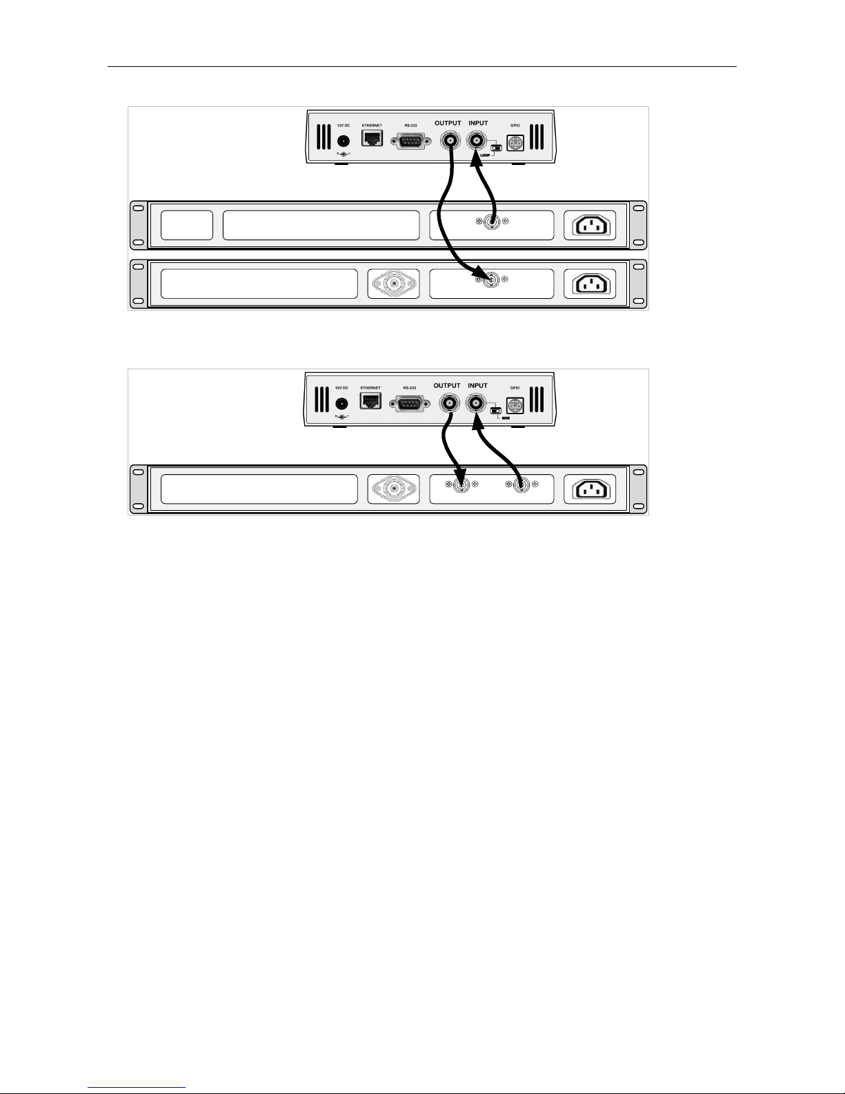
Installation and Setting-up .....................................................................................................................................................7
5.1
Connection .............................................................................................................................................................................7
5.2
On-board Controls ................................................................................................................................................................8
5.3
Power Supply ........................................................................................................................................................................9
5.4
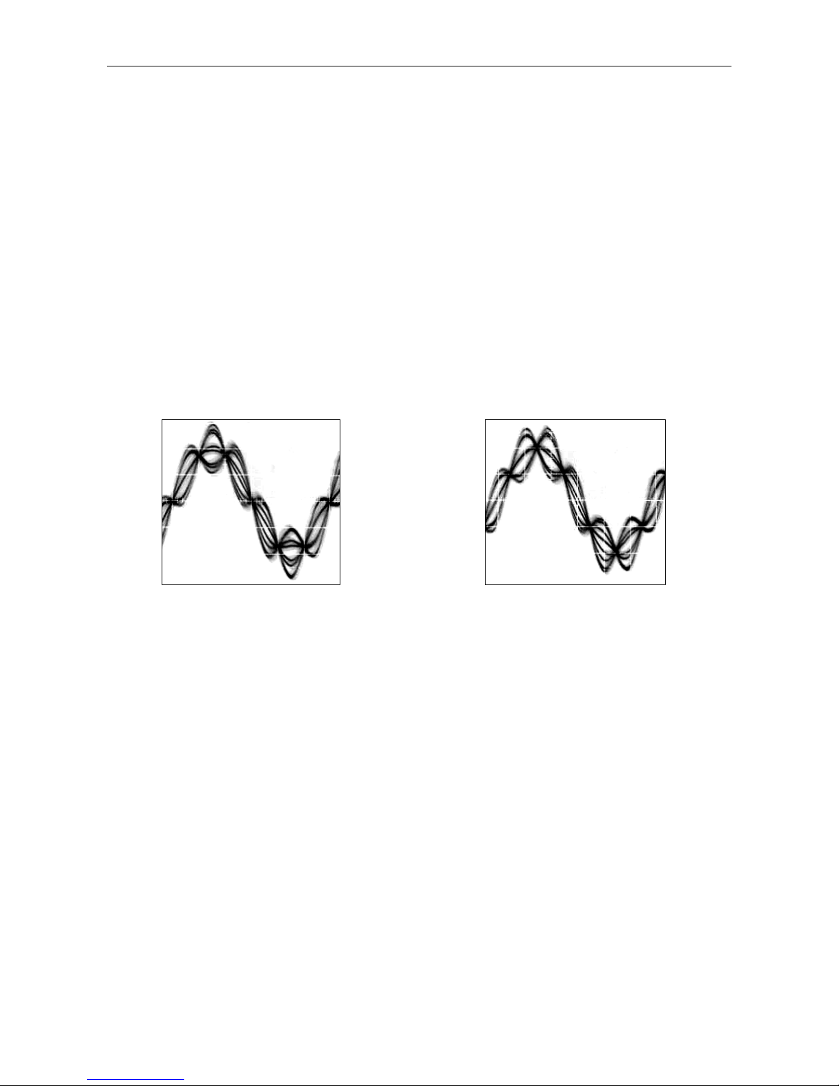
Level and Phase Adjustment...............................................................................................................................................9
5.5
Setting Basic RDS Data.......................................................................................................................................................11
6
Dynamic PS Text.....................................................................................................................................................................14
7
Alternative Frequencies.........................................................................................................................................................1
7.1
Method A .............................................................................................................................................................................15
7.2
Method B..............................................................................................................................................................................16
8
Enhanced Other Networks information (EON) control ...................................................................................................17
9
Weekly Scheduling.................................................................................................................................................................18
10
Broadcast Automation System Link-up..............................................................................................................................19
10.1
Indirect Link ........................................................................................................................................................................19
10.2
Direct Link ...........................................................................................................................................................................19
11
Communication Ports.............................................................................................................................................................21
11.1
Overview..............................................................................................................................................................................21
11.2
Working with a Terminal Application.............................................................................................................................22
11.3
Command Interpreter.........................................................................................................................................................23
11.4
Additional Information......................................................................................................................................................24
12
List of Commands...................................................................................................................................................................26
12.1
Command Summary ..........................................................................................................................................................26
12.2
Basic Commands.................................................................................................................................................................29
12.3
EON Commands .................................................................................................................................................................35
12.4
Messages Commands .........................................................................................................................................................36
12.5
Scheduling Commands ......................................................................................................................................................37
12.6
System Commands .............................................................................................................................................................38
12.7
Advanced Commands........................................................................................................................................................40
12.8
Memory Organization........................................................................................................................................................45
12.9
Dynamic PS 1 and Dynamic PS 2 Summary....................................................................................................................45
13
Further Features.......................................................................................................................................................................46
13.1
Bypass Relay........................................................................................................................................................................46
13.2
LED Indication ....................................................................................................................................................................46
13.3
External Program Set Switch .............................................................................................................................................46
13.4
External TA/EON1TA Switch...........................................................................................................................................46
13.5
Internet unctions ...............................................................................................................................................................47
13.6
Showing Real Time in Dynamic PS ..................................................................................................................................47
13.7
Real-Time Backup ...............................................................................................................................................................47
13.8
irmware Upgrade..............................................................................................................................................................47
13.9
On-line Support...................................................................................................................................................................47
14
Universal Encoder Communication Protocol (UECP).......................................................................................................48
14.2
Traffic Message Channel (TMC) Application Notes ......................................................................................................51
1
Annexes..................................................................................................................................................................................... 2
15.1
Character set and code-table conversions........................................................................................................................52
15.2
Communication Protocol Implementation lowcharts..................................................................................................53
15.3
RDS Group ormat .............................................................................................................................................................56
15.4
Troubleshooting ..................................................................................................................................................................59

3
1 Introduction
The P332 RDS encoder is a result of more than 10 years experience collecting and presence on the market. It is
especially developed for regional and national stations but can suit for other stations as well. Depending on technical
requirements, it may be used as an economical alternative to industry standard RDS encoders.
ully digital concept and uniquely effective design ensures high reliability, excellent signal characteristics and gives
the user many advanced features while maintaining low acquisition costs. The encoder includes RS-232 port for
direct connection to serial data source, e.g. satellite receiver. Built-in Ethernet controller supports multiple TCP/UPD
ports, internet functions and remote monitoring.
1.1 Main Highlights
ully dynamic M broadcast RDS encoder with up to four independent communication ports
Optically isolated RS-232 port
Ethernet connectivity
Supports internet functions and remote monitoring
Control interface based on ASCII commands and UECP protocol
Text features include dynamic PS, parsing, scrolling, fixed messages, scheduling and HTTP reading
Excellent compatibility with broadcast automation systems
Control software includes powerful Windows GUI application
Built-in weekly scheduling
Supports control from external PHP/ASP scripts
Easy and fast set-up
1.2 Other eatures
Excellent spectral purity, direct digital RDS signal synthesis; compliant with EN 50067 / EN 62106
irmware updates are free
Two switchable program sets (with optional DSN and PSN setting)
External TA and Program set switch
Bypass relay, high reliability
Switchable MPX loopthrough mode (Loop/Side)
Internal real-time clock incl. backup battery
No special 19 kHz input needed - pilot tone internally recovered from MPX signal using digital PLL
Compatible with P132 type, backward compatible with PIRA32
CE conformance notice:
This device complies with the requirements of the EEC Council CE marking and EMC directives.
Harmonized standards applied: EN 55022 (B ITE class), EN 55024.
Please read this entire manual and familiarize yourself with the controls before attempting to use this equipment.
Where not otherwise indicated, any information mentioned in relation to the RDS (Radio Data System) applies in full
also to the RBDS (Radio Broadcast Data System).
The equipment has been thoroughly tested and found to be in proper operating condition when shipped. The
manufacturer is not liable for any damages, including but not limited to, lost profits, lost savings, or other incidental or
consequential damages arising out of the use of this product.
No part of this manual may be reproduced or transmitted in any form or by any means, electronic or mechanical,
including photocopying, recording or information storage and retrieval systems, for any purpose other than the
purchaser's personal use.
Information in this document is subject to change without notice.
If you have any questions or comments regarding this document, please contact us via email.
We welcome your feedback.
Revision 2015-09-19
Copyright © 2015 PlRA DigitaI s.r.o.

4
2 Technical Specifications
Parameter Condition Value
General
Supply voltage 12 V DC stabilized
Supply current 340 mA
Signal connectors unbalanced BNC
Data connectors 1x RS-232 (port 1), 1x Ethernet (port 2, 3, 4)
Network protocols supported HTTP, SNTP, TCP, UDP, DHCP, DNS, SNMP
RS-232 communication speed software switchable 1200, 2400, 4800, 9600, 19200 bps
RS-232 communication mode 1 stop bit, 8 data bits, no parity, (no flow control),
ASCII or UECP (SPB 490)
TA switching software or external switch
TA/EON1TA input TTL with 10 kΩ pull-up, level or falling edge activated
Program sets 2
Program set switching ASCII command, UECP command or external switch
Program switch input TTL with 10 kΩ pull-up, level controlled
RDS Services directly supported PI, PS, PTY, TP, A , TA, DI, M/S, PIN, RT, RT+
TMC, EON, PTYN, ECC, LIC, TDC, IH, CT, ODA
RDS signal
Subcarrier frequency 57 kHz
Bandwidth ± 2.4 kHz (50 dBc)
Output level adjust 0.0 to 4.0 V p-p in 256 steps
Phase shift adjust stereo
transmission ull range, in 9.5 deg. steps
Audio/MPX/Pilot input
mono < 10 kΩ
Recommended load impedance stereo MPX < 2 kΩ
Recommended MPX voltage 1.3 - 8.0 V p-p
Passthrough voltage gain 2 Hz - 100 kHz 1 (0 dB)
Pilot tone level min. 120 mV p-p
- recommended M deviation
6.8 kHz
Pilot PLL capture range 8 Hz
Stereo encoder pilot frequency
required
stereo
transmission 19000 Hz ± 2 Hz
Output
Output impedance 100 Ω
Recommended load impedance > 70 Ω, < 1 n , no DC offset
Max. output voltage (RDS + MPX) 9.0 V p-p
Recommended RDS level 3 - 11 % of MPX
Notes: p-p - peak-to-peak value
The unit can operate with mono transmitter as well.

3 Block Diagram
Output
Input
P1 2
Microcontroller
RTC
EEPROM
A
D
Ethernet
Module
Optical
Isolation
Ethernet
Socket
RS-2 2
Connector
LCD Display
J1
Relay
I
2
C
Digital output
level control
SIDE/LOOP
LED Indicators
Program
TA
Pilot/MPX
Power
Supply
5V
V
Analogue Part
Digital Part
Ethernet Module

6
4 Physical Description
4.1 Board Layout
4.2 Connectors
J2 – 12 V power supply connector (2.1 mm)
Central pin is positive (+)
J3 – Output
J9 – Ethernet socket
P1 – RS-232 connector (DB9 male)
See section 11 for pin diagram.
J7 – Pilot or MPX input
J12 – Logical control inputs
1: Program switch input
2: (not connected)
3: Ground
4: 5V Output (max. 50 mA)
5: (reserved)
6: TA/EON1TA switch input
J19 – 5 V Output for LCD backlight
1: +5V
2: Ground
J10 – LCD display output (driving HD44780)
1 GND 9 GND
2 +5V 10 GND
3 V0 11 DB4
4 RS 12 DB5
5 GND 13 DB6
6 E 14 DB7
7 GND 15 +5V BKLT
8 GND 16 GND
4.3 Adjustable Elements
J1 – MPX loopthrough switch
R 4 – LCD contrast trimmer
4.4 LED Indicators
LED1 – Operation / Receive data / Error
LED2 – Pilot tone indication / irmware update
B1 - Lithium battery 3 V for real time backup. Estimated endurance is 10 years. Replace by CR2032 type.
Note: EEPROM memory which is used for R S data storage does not require any voltage to hold the data.

7
Installation and Setting-up
5.1 Connection
Basic rules:
The RDS signal must be fed into modulation input (added to MPX signal if stereo encoder is used).
If stereo encoder is used, one of its outputs (MPX or pilot tone) must be fed into the RDS encoder input to meet
the synchronization requirement.
ollowing figures show various situations and corresponding methods of connection:
Stereo encoder
FM Transmitter
RDS Encoder
MPX inputRDS/SCA/MPX input
Pilot/MPX outputMPX output
Separate stereo encoder - default connection.
Stereo encoder
FM Transmitter
RDS Encoder
MPX input
MPX output
RDS/SCA/MPX input
Stereo encoder with only one MPX output provided.
Stereo encoder
FM Transmitter
RDS Encoder
MPX output
MPX input
RDS/SCA input
M transmitter with only one MPX input provided.

8
Stereo encoder
FM Transmitter
RDS Encoder
MPX input
MPX output
Both stereo encoder and M transmitter with only one MPX connector provided - loopthrough mode.
It is recommended not to use this mode if any of the other connections are possible.
FM Transmitter with
integrated stereo encoder
RDS Encoder
Pilot/MPX outputRDS/SCA/MPX input
M transmitter with integrated stereo encoder.
In case of mono transmission (no stereo encoder used) the RDS encoder input may be left unconnected (since there is
no need of external synchronization) or it may be used for the audio signal injection in the case that the M
transmitter has only one input connector.
5.2 On-board Controls
.2.1 On-board adjustable elements
Due to completely DSP-based solution there’s no adjustable element on the board affecting the RDS or MPX signal.
.2.2 J1 - MPX loopthrough switch
Set the switch to LOOP position only if you want to pass the input signal to the output of the RDS encoder
(loopthrough mode). In all other cases the switch must be set to SIDE position!

9
5.3 Power Supply
The RDS encoder can be supplied from any power supply, which delivers a stabilized voltage of 12 V DC and a
current of at least 500 mA and no more than 2 A. The RDS encoder has built-in polarity protection. The central
conductor of the power supply connector is positive (+).
Note: After first power-up the R S encoder will start to generate the R S signal with factory default values
(PS: * R S *, PI: FFFF). There is no need to configure anything to turn on the R S subcarrier.
5.4 Level and Phase Adjustment
.4.1 RDS signal output level
Important note: There is no universal setting for the R S level. ue to different input sensitivity of different FM
broadcast equipment it's preferred always to check and adjust the R S level.
The correct level should be between 2 and 11 % of the audio multiplex signal, measured by oscilloscope in peak-to-
peak values on the modulator input. Recommended value is such that results in 3.4 kHz deviation of the M carrier.
Don’t forget that the maximum total M carrier deviation with RDS and MPX signal is 75 kHz. It is much easier to
use any M broadcast analyzer for setting the RDS level precisely.
Adjusting higher RDS level results in better RDS reception in areas covered with weak signal. This is especially
important if using scrolling PS or sending a lot of text information. However consider following aspects before
adjusting higher RDS level:
- the MPX (audio) level must be decreased a little to meet the overall M deviation limit,
- automatic tuning using alternative frequencies (A ) will appear slower – the receiver will rate the signal
reception as good although there may be a reason to tune to another frequency.
The deviation range of the M carrier caused by RDS/RBDS is 1.0 to 7. kHz.
The deviation range of the M carrier caused by stereo pilot tone is 6.0 to 7. kHz.
The overall peak frequency deviation shall not exceed 7 kHz.
The RDS level can be adjusted after establishing a connection to the encoder, using one of these two methods:
In the Windows software
Go to Options – Preferences – Control and check the item ‘Enable RDS level control’. Now the control is available on the
System sheet in the main window.
The software allows adjusting the RDS level in range 0.4 to 100 %. In the P332 RDS encoder, that range is
proportional to the output level range of 15.6 to 4000 mV p-p. Confirm the setting by Store button.
In the embedded website
Click on menu item Setup – Signal Control and enter the RDS level directly in mV p-p unit.
In terminal, using ASCII command LEVEL=
The P332 RDS encoder allows direct adjusting of the RDS level in 256 steps, in range 0 to 255, by assigning a
corresponding value to the LEVEL parameter. Each step represents approx. 15.6 mV increase.
Desired step count can be calculated as
1
4000
256 −
×= levelRDSOutput
LEVEL
Actual output RDS level (in mV p-p) can be calculated as
4000
256
1×
+
=LEVEL
levelRDSOutput

10
.4.2 Phase adjustment for stereo transmission
The phase adjustment between RDS subcarrier and pilot tone is an optional procedure applicable for stereo
transmission (for mono there’s nothing to adjust). The adjustment is made using the Windows control software or
using the PHASE= command. Make sure the external synchronization is enabled (check the command EXTSYNC or
the item Clock source on the System card in the Windows control software which must be set to Auto).
rom factory the phase shift is already set to 0 degrees so user may skip this chapter.
1. etch pilot or MPX signal to the RDS encoder. The PILOT LED will indicate that the pilot tone is present.
2. Adjust right phase shift (0 or 90 degrees phase shift between 19 kHz pilot tone and 57 kHz RDS subcarrier,
measured on transmitter input, see the oscillograms). The phase adjustment would be difficult without an
oscilloscope or specialized measuring instrument.
Some experiments performed in the field show that the conditions of RDS reception are not too much affected
by the phase criterion. However, similar experiments have shown that right phase shift adjust offers a better
behaviour of audio receivers, and notably the residues of audio intermodulation which can sometimes be
observed, but with the aid of professional instruments only.
Conclusion: The phase adjustment is only optional and you may skip this step. Make sure the pilot tone is
indicated on the R S encoder by the PILOT LE .
Oscillograms
Pilot and RDS in phase
(0 degrees phase shift)
Pilot and RDS in quadrature
(90 degrees phase shift)
Measuring conditions: Two-channel analogue oscilloscope, CH1: pilot (or MPX without audio), CH2: RDS
output, trigger source: CH1, vertical function: CH1+CH2, horizontal: 5 µs/div.

11
5.5 Setting Basic RDS Data
Before getting on-air with the RDS signal, you will need to decide on the settings to be used. The following RDS
services must be set as the first. Use the Windows control software and its GUI or use the embedded website. or
more experienced users or those without a Windows PC, any terminal programme can be used (see chapter 11).
Note: When attempting to set-up a unit that was already placed in operation before, the user should apply the
initialization first (chapter 12.2 or Windows control software help or embedded website menu item Factory
defaults).
. .1 PI (Program Identification)
This is very important information that enables the receiver to distinguish between countries, areas in which the
same program is transmitted, and the identification of the program itself. The code is not intended for direct display
and is assigned to each individual radio program, to enable it to be distinguished from all other programs.
The PI code consists of four characters (hexadecimal numbers).
The first character identifies country:
0 Cannot be assigned. 8 PS, BG, LV, PT
1 DE, GR, MA, IE, MD 9 AL, DK, LI, LB, SI
2 DZ, CY, CZ, TR, EE A AT, GI, IS
3 AD, SM, PL, MK B HU, IQ, MC, HR
4 IL,CH, VA C MT, GB, LT
5 IT, JO, SK D DE, LY, YU
6 BE, I, SY, UA E RO, ES, SE
7 RU, LU, TN, NL EG, R, NO, BY, BA
The second character identifies program type in terms of area coverage:
0 Local Local program transmitted via a single transmitter only during the
whole transmitting time.
1 International The same program is also transmitted in other countries.
2 National The same program is transmitted throughout the country.
3 Supra-regional The same program is transmitted throughout a large part of the
country.
4 to Regional The program is available only in one location or region over one or
more frequencies, and there exists no definition of its frontiers.
The third and fourth characters are used to clearly identify different stations within the area of coverage.
Important note: Meaning of some PI digits may be different for US RB S.
Important note: If the station has only one transmitter, second PI digit must be zero (x0xx).
Important note: Factory default PI value is FFFF and it's needed to change it as soon as possible to avoid the
situation that two different stations with common area of coverage have the same PI. For each station in the same
location the unique PI must be assigned. Stations that carry different program must be unambiguously identified by
the last two PI digits. In other case they are recognized as one station by car radios, regardless of any other service
settings. If the broadcaster hasn't received the 4-digit PI from authority, he must choose such number that is not in
conflict with other stations in the location.
Tip: The Magic R S control software includes a wizard that calculates the PI automatically.

12
. .2 PS (Program Service name)
The PS name is max. 8 character long radio station name that will be shown most of the time on the radio display.
Advanced use of the PS (Dynamic/Scrolling PS) is discussed later.
. .3 PTY (Program Type)
The PTY code defines the type of the programme broadcast within 31 possibilities. See chapter 12.2 for a complete
list. This code could be used for search tuning.
Important note: PTY number 1 (News) should never be left on all the time. Use PTY number 3 (Info) for this purpose.
. .4 TP (Traffic Program)
This is a flag to indicate that the tuned program carries traffic announcements. The TP flag should only be set on
programs which dynamically switch on the TA identification during traffic announcements. The flag shall be taken
into account during automatic search tuning.
. . MS (Music/Speech)
This is a two-state signal to provide information on whether music or speech is being broadcast. The signal would
permit receivers to be equipped with two separate volume controls, one for music and one for speech, so that the
listener could adjust the balance between them to suit his individual listening habits.
. .6 AF (Alternative Frequencies)
The Alternative requencies are used to tell receivers what frequencies they can receive the radio station on. This
facility is particularly useful in the case of car and portable radios. or this to work, each transmitter must have RDS
with the same PI code.
Important note: If second PI digit is set to zero (x0xx), this indicates that the station has only one transmitter and
the AF list is ignored on most receivers.
For complete R S service description visit the website, section Support.

13
. .7 Windows control software - First steps
1. In the case of USB connection install the USB driver first. After this the communication port is accessible like
any standard serial RS-232 port, using COMx name, where x is the port number assigned in operating system.
The virtual COM port driver ensures compatibility also with older software although the connection is
physically realized via USB cable. Pure RS-232 connection requires no extra driver or settings.
2. Make sure the RDS encoder is connected and powered, all connectors are seated completely.
3. Run the Magic RDS software using Windows Start button.
4. Open the Preferences (Options - Preferences) and set up the connection parameters. Choose the Serial
RS232/USB connection type and select the COM port the RDS encoder is connected to. If the RDS encoder is
connected via USB and was recognized correctly in Windows, you may find/change the COM port number in
Windows Control Panels - System - Hardware - Device Manager or simply click on the List button.
5. Close the Preferences. You should see "Connected" or "Opened" in the status bar. Now you are ready. The
settings are saved automatically.
6. Configure the basic RDS settings mentioned above. You will find them on cards Program and System. Then
click Store. For beginners there’s a very useful configuration wizard under menu item Help.
7. The status bar at the bottom of the window shows whether the data was sent successfully. If Communication
Error! is shown, check the connection to the RDS encoder, its power supply and that the correct COM port is
selected in the Preferences dialogue box.
8. ollow the instructions in the application Help and in the document ‘P132 RDS Encoder - Communication
Ports and Internet Functions’.
Magic RDS 3 - default Windows control software.
Note: The R S encoder contains two types of memory. These are marked as RAM and EEPROM. Like any other
computing system the RAM holds all operational data which are also used for transmission whilst the EEPROM is
used for the data storage during power-off. By default the button Send will fill the RAM only. The button Store will
fill the RAM and also stores the data into EEPROM. The Store button behavior can be changed in Options -
Preferences - Buttons.
If the user forgets to store the data into EEPROM, the settings will be lost when the power is disconnected.
Dynamic PS 1
text
Status bar
RT+ indicator
Radiotext 1
Default PS
Main menu
Tool bar
Configuration
wizard

14
6 Dynamic PS Text
Standard RDS enabled receiver disposes of 8-character LCD display but we usually need to show pile of information
and commercials. So small display on the one hand and so much demands on the other hand. The P332 solves it by
unique system of text messages showing. Although Radiotext service is defined in the RDS standard, this service is
not present some receivers (especially older car radios) and has some other limitations. According to the broadcasters
needs, the PS service - one of the basic RDS services supported by all receivers - can be usually used to give
sequential information. This has become known as ‘Dynamic PS’ or ‘Scrolling PS’.
Note: Using the dynamic PS is restricted in some countries and it's fully prohibited by the R S standard!
The manufacturer is not responsible for incompetent use of this feature. Some receivers may not display the dynamic
PS properly for reasons that lie entirely on their side. Never provide traffic information inside the ynamic PS text!
The P332 RDS encoder offers advanced implementation of the Dynamic PS service. Basic text message length is up to
255 characters (mode independent). Two varieties of the Dynamic PS are present: Dynamic PS 1 (DPS1) and Dynamic
PS 2 (DPS2). Both varieties are configurable independently from each other.
Basic configurable parameters are:
Text content/text source
Display mode
Label period or scrolling speed
Number of transmissions
Example of full dynamic PS use:
The number of transmissions is specified for each Dynamic PS text. The Static PS period (delay between text loops)
specifies the time between two repeats of the Dynamic PS text loops. Default PS is displayed during this time.
our display modes are provided. The mode is switchable ‘on the fly’, without need to re-enter the text message.
Mode 0 - Scrolling by 8 characters
Mode 1 - Scrolling by 1 character
Mode 2 - Word alignment scrolling
Mode 3 - Scrolling by 1 character, text separated by spaces at begin and end
Additional differences exist between Dynamic PS 1 and Dynamic PS 2 (see sections 12.2 and 12.9). In general the
DPS1 should be used if on-line connection is available between your studio and the RDS encoder while the DPS2
should be used if the RDS encoder is placed on a site without on-line connection providing set of fixed messages.

1
7 Alternative Frequencies
The list of alternative frequencies gives information on the various transmitters broadcasting the same program in
the same or adjacent reception areas. It allows switching to another frequency of the same station when leaving the
actual frequency coverage. This facility is particularly useful in the case of car and portable radios.
Important note: If second PI digit is set to zero (x0xx), this indicates that the station has only one transmitter and
the AF list is ignored on most receivers.
Ideally the A list should only comprise frequencies of neighboring transmitters or repeaters. Entire A set should be
as tiny as possible to allow the receiver to find the strongest frequency quickly. This will improve the listener's
experience. Thus there should be more RDS encoders using individual A sets within larger networks.
Two methods of A transmitting are possible:
• A method A is used for stations carrying the same program on all their transmitters. The list may contain up to
25 frequencies.
• A method B is used for larger lists or when splitting areas or different programs are broadcast.
7.1 Method A
This is a default method recommended for most of stations.
To establish a common list of AF-A using a terminal:
Note: Requires only one R S encoder for entire network (common STL or one main transmitter and two
repeaters). The list must contain all frequencies on which the signal from the R S encoder is carried.
AF=94.3,95.8,91.2
*AF
Enter the list
Store the list
To establish a separate list of AF-A for each transmitter:
Note: Requires separate R S encoder for each transmitter.
Note: All R S encoders must be using the same PI (Program Identification).
91.2 MHz:
AF=94.3
*AF
Enter the list
Store the list
94.3 MHz:
AF=95.8,91.2
*AF
Enter the list
Store the list
95.8 MHz:
AF=94.3
*AF
Enter the list
Store the list
9 .3 MHz
91.2 MHz
95.8 MHz

16
7.2 Method B
Total capacity: up to 8 lists, up to 12 A pairs each
Method B A coding is a more complex method that is used where the number of A s used by a transmitter and its
associated repeater stations exceed 25, or where it is required to indicate frequencies which belong to different
regions which at times carry different programs.
More than one transmitter or associated repeaters of the station broadcast the same set of different A lists in
sequence. Total number of A lists used within entire network is in general identical to the number of transmitters
and repeater stations in the network so as to provide a unique list for each transmitting station. In this method the
alternative frequencies are individually addressed by transmitting the tuning frequency paired with one alternative
frequency. Each list starts with the tuning frequency for which the list is valid, e.g. 94.3. All remaining pairs (up to
12) give the tuning frequency together with a valid A .
or the transmission of the frequency pairs within one block the following convention is used. They are generally
transmitted in ascending order ( 1 < 2), e.g. 94.3,95.8 or 91.2,94.3. In special cases they are transmitted in
descending order, if they belong to different regions, or carry from time to time different programs. If you use the
Windows control software, this assures right order automatically.
To establish a common set of AF-B lists using a terminal:
Note: For illustration purpose only. If the network contains only a few frequencies like in this example, the
method A is more effective.
AF=A
AF=94.3,94.3,95.8,91.2,94.3
*AF=1
AF=95.8,94.3,95.8
*AF=2
AF=91.2,91.2,94.3
*AF=3
AF=
*AF=4
AF=B
*AF
Switch to method A to allow editing of the A lists
Enter the first list for 94.3 MHz
Store the list
Enter the second list for 95.8 MHz
Store the list
Enter the third list for 91.2 MHz
Store the list
Terminate the set of A lists
Store the termination
Switch back to method B – start cycling through the lists
Store the method setting
To read the set of AF-B lists:
AF
AF=A
AF=1
AF
AF=2
AF
AF=3
AF
AF=4
AF
AF=B
Read the A method being used (A/B)
Switch to method A to allow reading of the A lists
Load the first list
Read the list
Load the second list
Read the list
Load the third list
Read the list
Load the fourth list
Read the list, no A here, terminating
Switch back to method B
Notes:
If the number of AFs of a station is larger than 12, the list must be split into two or more lists. These lists are
transmitted directly one after the other.
Broadcasters using splitting of a network during certain hours of the day should use AF method B, and not AF
method A. The lists should be static, i.e. the AFs included in the list, carrying a different program during certain
hours of the day, shall be signaled by transmitting in the descending order (F1 > F2). Their PI shall differ in the
second digit of the code (using regional variant 4 to F) and may also be static. Switching the second digit of the PI to
1, 2 or 3 informs the receiver that now even AFs transmitted in descending order carry the same program and the
receiver may use them for switching.

17
8 Enhanced Other Networks information (EON) control
The EON feature is used to update the information stored in a receiver about program services other than the one
received. Alternative frequencies, the PS name, Traffic Program and Traffic Announcement identification as well as
Program Type and Program Item Number information can be transmitted for each other service. The relation to the
corresponding program is established by means of the relevant Program Identification (PI).
The EON is especially useful for linking two or more stations of the same owner. Most of EON featured receivers
gives priority to stations linked by EON when seek function is activated. Since the P332 can store four EON links, up
to 5 stations can be linked together.
Station that doesn’t carry traffic announcements can refer to a station that does. This situation is described below. or
more information see appropriate section in the List of Commands or in the Magic RDS control software help.
8.1.1 Traffic Program and Traffic Announcement codes
The coding to be used is as follows:
Traffic Program
(TP)
Traffic Announcement
(TA) Applications
0 0 This program does not carry traffic announcements nor does it
refer, via EON, to a program that does.
0 1 This program carries EON information about another program
that gives traffic information.
1 0
This program carries traffic announcements but none are being
broadcast at present and may also carry EON information
about other traffic announcements.
1 1 A traffic announcement is being broadcast on this program at
present.
Station which uses the code TP=0, TA=1 must refer to at least one program service which carries traffic information,
and has the flag TP=1. When a particular program service begins a traffic announcement, the station that cross-
references this service via the EON feature will broadcast a switch signal by setting the appropriate EON TA flag to 1.
The EON TA flags can be controlled by software for all four EON links in the P332. The first EON link TA flag can be
also controlled by external TA/EON1TA switch.
The situation described is illustrated on the example below:
8.1.2 Example
Kiss M is a small station that doesn’t carry traffic announcements but refers via EON to City Radio, which is
regional station of the same owner that carries the traffic announcements. If the Kiss M listener has activated the
EON feature on his receiver, he will be automatically tuned to City Radio for the duration of traffic announcements.
Station 1: Kiss FM
PI=20 1
PS=KISS M
TP=0, TA=1
requency: 90.2 MHz
Station 1 EON Data:
EON1PI=2501
EON1PS=CITY
EON1TA=(controlled by external switch)
EON1A =93.7
Station 2: City Radio
PI=2501
PS=CITY
TP=1, TA=(controlled by external switch)
requencies: 93.7 and 106.2 MHz
(only 93.7 can be received in the area covered by Kiss M)
Both TA/EON1TA switch connectors can be wired together and controlled by only one switch or device if the
transmitters of 90.2 and 93.7 MHz are placed on the same site.

18
9 Weekly Scheduling
This feature allows scheduling of text messages, program type names and any other commands in hourly, daily and
weekly program. The scheduling is provided directly by the P332 unit. Once set, it works with no more support from
PC or control application. This is especially useful when the RDS encoder is placed on remote site or where reliability
is important.
9.1.1 Key features
The scheduling feature is fully implemented in the P332 unit and works independently
Almost any RDS service or control command can be scheduled
Up to 48 scheduling items
Each item may contain any combination of days in week, up to 12 times (a wildcard is supported on the hour
place), program type (PTY) information and any from more than 60 commands
9.1.2 First steps
Let’s say that our radio station called ‘PRO 88’ broadcasts news from Monday to riday at midday. The news
duration is 40 minutes. During the news the PS is set to ‘HOT NEWS’ and the PTY is set to 1 (News). In common
program the PTY is set to 3 (Info).
Scheduling item 01:
Days: Monday, Tuesday, Wednesday, Thursday, Friday
Times: 12:00
PTY: 1 (News)
Command: PS=HOT NEWS
Scheduling item 02:
Days: Monday, Tuesday, Wednesday, Thursday, Friday
Times: 12:40
PTY: (Info)
Command: PS=PRO 88
9.1.3 Text messages scheduling
Although it’s possible to change directly the Dynamic PS and Radiotext (using an appropriate command, for example
RT2=The best m sic in the city), the maximum text length is limited since maximum command length in
each Scheduling item is 35 characters. or longer texts you may use indirect method based on the bank of Messages:
1. Store the text as a Message, for example Message 01.
2. In the Scheduling call the message number, for example RT2MSG=1 or DPS2MSG=1.
The Windows control application provides easy GUI for this case.
9.1.4 Troubleshooting
If the scheduling doesn’t work as expected, check the following points:
Scheduling enabled?
Date and Time actual?
Commands typed right?

19
10 Broadcast Automation System Link-up
To send dynamic data via the RDS it's very useful to link the RDS encoder with your broadcast automation system.
This usually results in a possibility of sending commercials, actual song information, program announcements and
more. Almost any broadcast system can be linked with the P332. The link may be either indirect or direct.
10.1 Indirect Link
Default Windows control software for the P332 RDS encoder is the Magic RDS 3. This application including
documentation and examples of use can be downloaded from the Website, section Software.
Since probably hundreds of automation systems are used around the world and new versions are released often,
information in this manual cannot be full-scale. or more information about how to configure the broadcast
automation system text output read its documentation or contact the vendor.
10.2 Direct Link
10.2.1 Recommended procedure step-by-step
1. or the present turn off the RDS encoder support in the broadcast automation system.
2. Connect the RDS encoder and configure all basic parameters like PI, default PS, text setup, individual text
features enable settings etc. using the Windows control software or terminal application and command line.
Store all setting into EEPROM. Exit the Windows control software or the terminal.
3. ind out the baudrate (speed) or network protocol that is used by the broadcast automation system for
communicating with the RDS encoder. Configure the connection parameters, using Device setup dialogue box
or a terminal. ollow the instructions in the document ‘P132 RDS Encoder - Communication Ports and Internet
Functions’.
4. Reset the RDS encoder if necessary for the network settings to take effect.
5. Turn on the RDS encoder support in the broadcast automation system.
Important note: By default only one software application can access one communication port at the same time!
or more information about how to control the RDS encoder contact the broadcast automation system vendor.

20
10.2.2 Compatibility commands
To reach the best possible compatibility with broadcast automation systems, the P332 includes a special set of
compatibility commands. In the systems where the P332 is not directly supported (or the system is older version) the
user may try to select another RDS encoder model to send text messages. Where possible, set the communication as
unidirectional.
Command Translated to
TEXT= RT1=
DPS= DPS1=
PS_SCROLL= DPS1ENQ=
Moreover the RDS encoder includes UECP support (see chapter 14).
10.2.3 Radiotext Plus (RT+)
The RT+ feature is designed to let the listener take additional benefit from the Radiotext service by enabling receivers
to offer direct access to specific elements of Radiotext. Typically the RT+ feature supports song artist and song title
elements. These elements anyway carried in the Radiotext, are identified by their class type, length and location
within the Radiotext. The receiver must be equipped with the RT+ function (also called "tagging") to take advantage
of this feature.
The RDS encoder includes full support for the RT+ and its handling is highly automated. or direct use your
broadcast automation system must support the RT+ function either by means of user defined groups or by the
command RTP= (see section 12.7 for more details). In other cases the Windows control software used in the indirect
link configuration can provide the RT+ service. Always make sure that the RT Type is set to ‘Toggle automatically’.
Other manuals for P332
1
Table of contents
Other RDS Media Converter manuals