SATSPEED-2 Interface / GPS-16 Receiver
KITS: K/SATSPEED2/W, K/SATSPEED2/C, K/SATSPEED2/S,
K/SATSPEED2/G, K/GPS16, K/GPS16/D9
User Instructions
Doc. No. S/DC/500-10-708 : Issue 5 - 8.10.13 Page 5 UK708500.DOC
General Installation Guidelines for the GPS Receiver
The GPS receiver has a magnetic base. A double-side adhesive foam pad and metal mounting plate isprovided in
the kit, to enable magnetic mounting onto non-magnetic surfaces.
Mount the antenna to give an unobstructed hemisphere of sky. This will ensure that GPS satellites are not
masked by parts of the vehicle, potentially reducing system performance.
Wherever possible, avoid drilling holes in the roof to avoid both water ingress and possibly wiring / air
conditioning equipment etc. If drilling is unavoidable, use silicone sealant around fixing and cable entry points.
Mount the antenna as far as possible from any equipment that can cause Electromagnetic Interference
(EMI)including DC motors (e.g. air conditioner), alternator, solenoids, CB radio, power cables, display units, or
other electronics. Excessive EMI will degrade system performance.
TIP: To detect possibly troublesome interference, tune a LW band portable radio off-station. With the aerial laid flat you
can then (hopefully) pick up the direction and source of the interference from the increase in noise. The antenna
can then be repositioned or if necessary, the source of the interference suppressed. If need be, contact RDS for
further advice on suppression methods.
Secure the antenna cable close to the antenna mounting (using cable ties) so that in the event the antenna is
knocked off it's magnetic mounting, it will be restrained and minimise the possibility of further damage.
Mount the antenna in the location for which you desire a position e.g. along the centre line of the vehicle and
as close as possible over the working interface.
NOTE: As this may well be impractical to achieve, the Pro-Series can be programmed via the ‘GENERAL PF SETUP‘
menu with ‘GPS ANTENNA OFFSETS’ to compensate for the difference in position of the antenna from the cutter
bar, spray boom etc (please refer to the "PSi PF Instruments Data Logging and Transfer" manual).
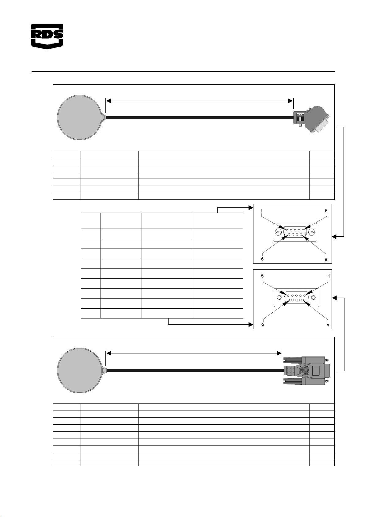
GPS 16 Setup (Standalone GPS input to PSi)
Connect the receiver to the top port on the PSi.
From the "SETUP" menu, select "Port Setup" and set the top port to "GPS Only".
From the "SETUP" menu, select the Speed Sensor Setup screen ( ), and select "NMEA VTG".
From the "General PF Setup" menu, select "GPS Baudrate" and select "19200".
After the initial power-on, allow up to 5 minutes for the receiver to automatically establish its position.
Subsequently the unit should establish position more quickly.
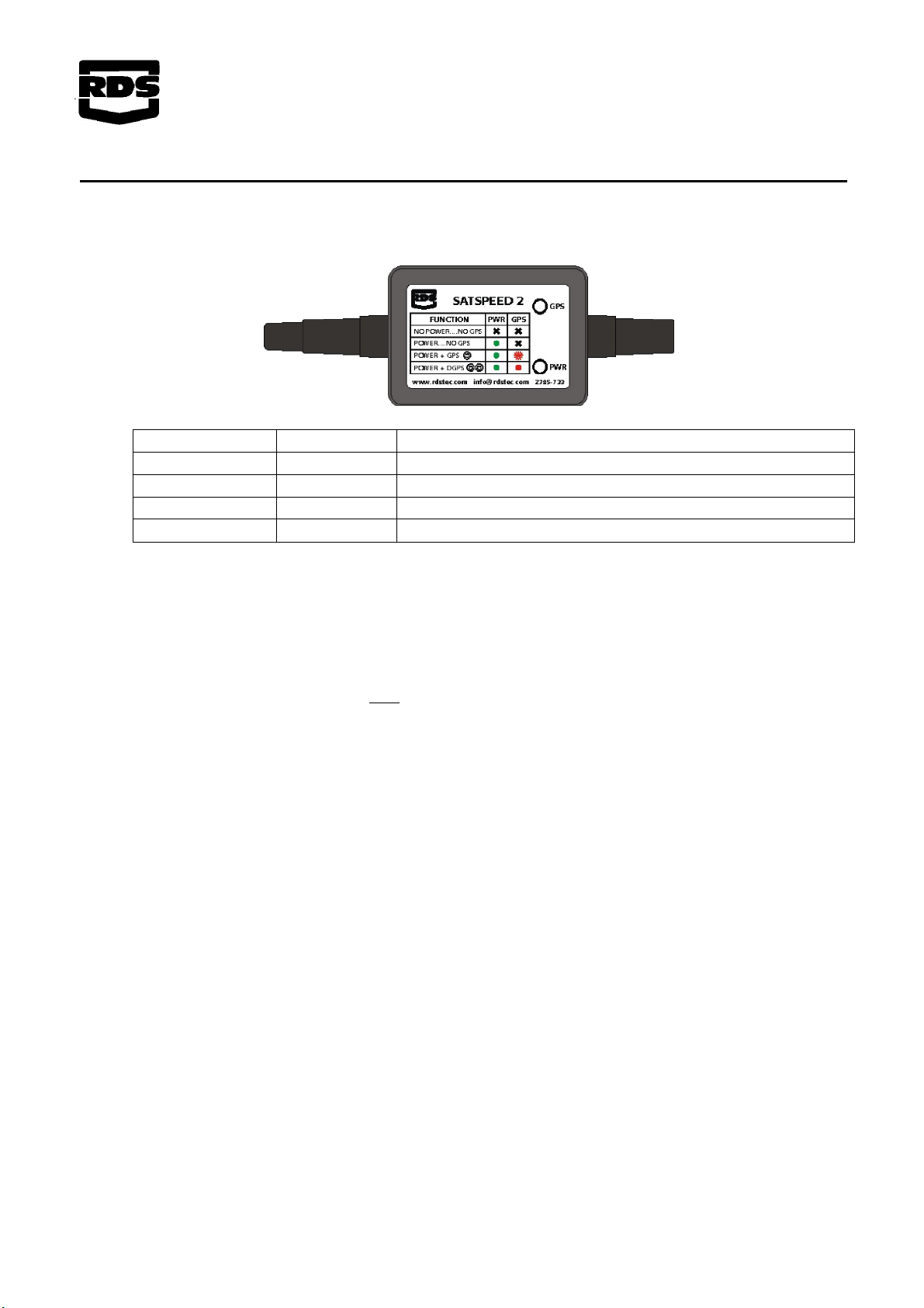
NOTE: The GPS icon at the top of the display indicates the status of the GPS signal.
GPS 16 Setup (Standalone GPS input to ISOCAN)
Please refer to the appropriate installation manual supplied with the product.