delayed signal is available after each chip. A
high signal–to–noise ratio is achieved thanks
to signal companding (dynamic compression
at the input matched with dynamic expansion
the outputs ensure optimal conditions for the
BBD chips to process the signal.
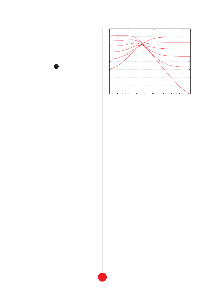
In general, the incoming signal must be band–
limited in order to prevent high frequency com-
ponents from interfering with the clock. Simi-
is processed helps to eliminate high frequency
artifacts introduced by the BBD chips. In Sara-
the current clock frequency, thus offering maxi-
mum bandwidth with minimal artifacts.
An internal feedback loop taken from the last
tap allows for the classic echo effect with ad-
ditional coloration offered by an adjustable tilt
externally while a crossfading circuit offers a
continuous mix of the input and the signal from
the last tap.
2. The signal you wish to process should be
patched to the input jack 1. The level knob
2above controls the amplitude with the in-
put indication multicolor LED 3providing
visual feedback. The outputs from individual
taps are labeled t1, t2, and t3, respectively:
4
,5
,6
. The central large t3time dial 7
allows for precise setting of the overall delay
time of the three stages, from about 20ms to
over 1.5s. The delay time can be modulated
via CV patched into the corresponding jack
below 8or synchronized to an external clock
source via the sync input 9. Since all three
BBD chips share a common clock, using the t1
and t2outputs will provide signals delayed by
1/3 and 2/3 of the t3time, respectively. The
mixed output 10 delivers a continuous mix of
your input signal and the t3tap. The balance is
controlled both by the effect knob 11 and the
CV patched into the mix cv jack 12
. The sig-
nal from the ext feedback loop input 13 is
mixed with the input of the delay line. This jack
is normalized to the t3output, however, the
connection can be broken by sending one of the
tap outputs to an external processor (such as
via the ext feedback loop input. Regardless
of the actual feedback signal path (internal or
external), the signal always passes through
tone slider 14 . The amount of feedback is
controlled by the fbck slider 15
. The bbd off-
range led 16 indicates that the delay time set
by the combination of the t3time dial and the
incoming CV signal exceeds the time range of
the module. When the CV inputs are in use, the
corresponding knobs act as offsets.
inPut SiGnAl
Sarajewo is AC coupled and accepts modular
level audio signals (10Vpp and higher). The
level knob attenuates the input to prevent
distortion (indicated by the color of the input
indication LED). When it turns from green
to yellow and then to red, it means the signal
is too hot and the BBD chips may introduce
audible distortion.
3