Reach RT-PoE5 User manual

Reach PoE5 Tester Manual 1.8 03/25/2021 Page 1
Reach PoE5 Tester Manual 1.8
Model RT-PoE5
Software Version 1.01 and above
March 25, 2021
© 2018-2021 Reach Technology, part of Novanta
All Rights Reserved
NOTE: The information contained in this user documentation is subject to change without
notice and does not represent a commitment on the part of Reach Technology. Reach
Technology assumes no responsibility or liability for any errors or inaccuracies that may
appear in this user documentation.
Reach Technology
www.reachtech.com
Sales
503-675-6464 ext. 2
sales@reachtech.com
Support
503-675-6464 ext. 1
techsupport@reachtech.com

Reach PoE5 Tester Manual 1.8 03/25/2021 Page 2
Table of Contents
1. REVISION HISTORY........................................................................................................... 4
1.1. RT-POE5 -BASE MODEL .................................................................................................. 4
1.2. RT-POE5 VARIATIONS...................................................................................................... 4
2. GENERAL.............................................................................................................................. 5
2.1. OVERVIEW......................................................................................................................... 5
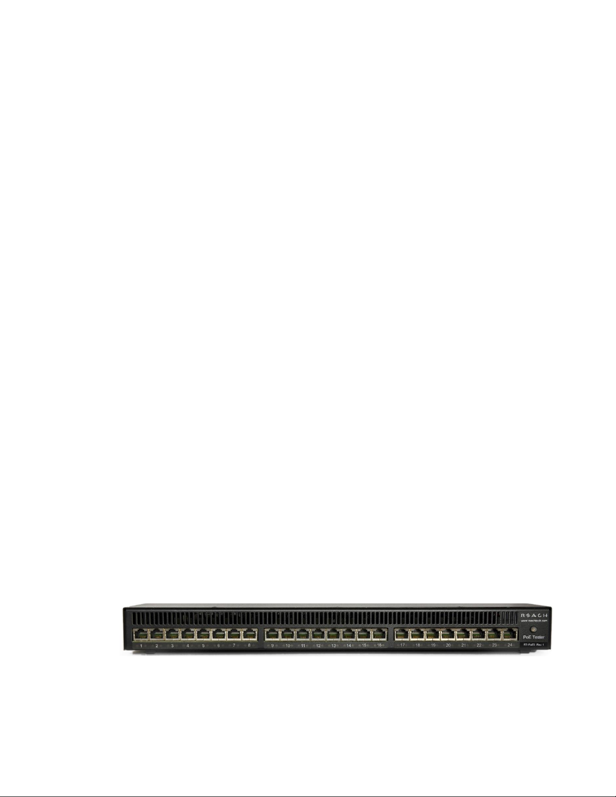
2.2. FRONT PANEL.................................................................................................................... 5
2.3. FEATURES.......................................................................................................................... 6
2.4. DIMENSIONS...................................................................................................................... 6
2.5. ELECTRICAL CHARACTERISTICS....................................................................................... 6
2.6. ENVIRONMENTAL.............................................................................................................. 6
2.7. WARRANTY....................................................................................................................... 6
2.8. OPERATING SOFTWARE..................................................................................................... 6
2.9. CALIBRATION.................................................................................................................... 7
3. CONFIGURATION GUIDE................................................................................................. 8
3.1. POWER............................................................................................................................... 8
3.2. SERIAL CONSOLE .............................................................................................................. 8
3.3. UUT CONNECTIONS.......................................................................................................... 9
4. CONNECTORS AND JUMPERS...................................................................................... 10
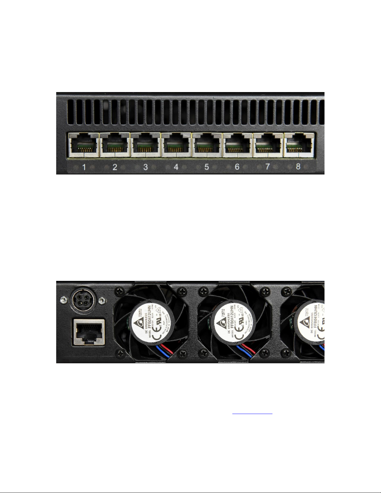
4.1. RJ-45 ETHERNET CONNECTORS...................................................................................... 10
4.2. REAR CONNECTORS ........................................................................................................ 10
4.3. ETHERNET POWER SELECTION........................................................................................ 11
5. OPERATIONAL OVERVIEW .......................................................................................... 12
5.1. DATA PATH...................................................................................................................... 12
5.2. POWER INPUT .................................................................................................................. 13
5.3. SIGNATURE,CLASS,AND LOAD....................................................................................... 14
5.4. DUAL/SINGLE SIGNATURE MODES ................................................................................. 15
5.5. FANS................................................................................................................................ 16
5.6. RJ45 LEDS...................................................................................................................... 16
6. ETHERNET CABLES......................................................................................................... 17
7. COMMAND REFERENCE................................................................................................ 18
EEPROM WARNING.................................................................................................................. 18
ECHO ........................................................................................................................................ 19
ERROR CHECK........................................................................................................................ 19
HELP ......................................................................................................................................... 19
VERSION.................................................................................................................................. 19
BAUD........................................................................................................................................ 20
BOOT ........................................................................................................................................ 20
HOSTNAME............................................................................................................................. 20
SHOW ALL............................................................................................................................... 21
CLEAR...................................................................................................................................... 21
LOAD........................................................................................................................................ 21
SAVE......................................................................................................................................... 22
PORT /GROUP PREFIX .......................................................................................................... 22

Reach PoE5 Tester Manual 1.8 03/25/2021 Page 3
CAP............................................................................................................................................ 22
CLASS –SINGLE SIGNATURE.................................................................................................... 23
CLASS –DUAL SIGNATURE...................................................................................................... 24
CLASS –AUTOCLASS................................................................................................................ 25
CONNECT ................................................................................................................................ 26
DETECT.................................................................................................................................... 26
EXT............................................................................................................................................ 26
GETI.......................................................................................................................................... 27
GETP ......................................................................................................................................... 27
GETV......................................................................................................................................... 27
INR ............................................................................................................................................ 28
MPS ........................................................................................................................................... 28
PSE ............................................................................................................................................ 29
POWER ..................................................................................................................................... 30
RESET....................................................................................................................................... 30
SET............................................................................................................................................ 30
SHORT ...................................................................................................................................... 31
SHOW........................................................................................................................................ 31
SINGLE..................................................................................................................................... 32
STATUS .................................................................................................................................... 32
TEMPERATURE ...................................................................................................................... 32
APPENDIX A - OPERATIONAL NOTES............................................................................... 33
A.1 POWER-ON....................................................................................................................... 33
A.2 ERROR MESSAGES ........................................................................................................... 34
A.3 INRUSH EXAMPLE WAVEFORM....................................................................................... 35
APPENDIX B - TEST SETUPS................................................................................................. 36
B.1 OVERVIEW....................................................................................................................... 36
B.2 SIGNATURE DETECT........................................................................................................ 36
B.3 CLASS DETECT,DUAL SIGNATURE MODE ....................................................................... 37
B.4 CLASS DETECT,SINGLE SIGNATURE MODE..................................................................... 38
B.5 POWER STATUS AND OVERLOAD (IEEE 802.3AF) .......................................................... 39
B.6 POWER STATUS AND OVERLOAD (IEEE 802.3AT).......................................................... 39
B.7 POWER STATUS AND OVERLOAD (IEEE 802.3BT,SINGLE SIGNATURE).......................... 40
B.8 POWER STATUS AND OVERLOAD (IEEE 802.3BT,DUAL SIGNATURE) ............................ 40
B.9 DATA TRANSMISSION UNDER POWER.............................................................................. 41
APPENDIX C - SPECIFICATIONS......................................................................................... 42
C.1 MEASUREMENT SPECIFICATIONS.................................................................................... 42
C.2 LIMITS............................................................................................................................. 42
APPENDIX D –MANUAL CHANGE HISTORY................................................................... 43

Reach PoE5 Tester Manual 1.8 03/25/2021 Page 4
1. Revision History
1.1. RT-PoE5 - Base Model
The Model RT-PoE5 is the initial version in production. It can be recognized by the
version string such as follows (see VERSION command; also seen on power-on).
Reach PoE Tester Model RT-PoE5/24
PN 53-0005-11 Rev A 0/1, SW 1.04, Jul 19 2019
Copyright (C) 2019 by Reach Technology, a Novanta Company
1.2. RT-PoE5 Variations
The PoE5 is available in a 24-port configuration, or in an 8-port configuration. All
‘number of port’ references in this manual show the full 24 ports, but the 8-port models
are limited to eight ports. There are no differences between the 24-port model and the 8-
port model other than the number of ports.

Reach PoE5 Tester Manual 1.8 03/25/2021 Page 5
2. General
2.1. Overview
Manufacturers of Ethernet Power Sourcing Equipment (PSE) such as Ethernet Switches
need to test PoE power functionality during manufacturing. Once a unit is in
manufacturing, it can be assumed that it has already been tested for full compliance with
the applicable IEEE 802.3 PoE standard. It is not cost-effective, nor necessary, to
perform full compliance testing at the manufacturing stage. What is needed is a
functional test that verifies the software’s ability to detect and control power, and the
basic connectors’and magnetics’ability to provide power and pass data.
The Reach RT-PoE tester family is designed for cost-effective, functional production
testing. It assumes that the PSE can be operated in a “diagnostic” mode whereby the
power control and detection functions of the PSE can be individually tested. Data
protocol features such as the Link Layer Discovery Protocol (LLDP) are not supported so
as to keep the cost of the tester low. Most switches provide a way of bypassing LLDP to
provide full power to a particular port. LLDP is implemented in firmware: if the unit can
pass data under power it can pass LLDP packets, and so testing LLDP functionality is not
necessary for a production test.
The Reach Power-over-Ethernet Tester Model RT-PoE5 provides diagnostic functional
testing of 24 PSE ports compatible with IEEE Standards 802.3af, 802.3at, and 802.3bt,
plus it will support data path speeds up to 10GBASE-T. It can draw up to 1000mA per
power pair (100W total over four pairs) while passing 10Gb traffic. It provides high
density with 24 Powered Device (PD) loads in a 1U high chassis.
Each RT-PoE5 section has a “UUT” port (Unit Under Test). The UUT port is connected
to the PSE and acts as a PD load to that port. The UUT data path is connected via power-
isolating magnetics to the adjacent UUT port (1 to 2, 3 to 4, 5 to 6, etc.). In this way, an
external data bit error tester or PSE test functionality can be used to test data integrity
while power load is enabled.
2.2. Front panel
Picture 1: Front of RT-PoE5
The front of the RT-PoE5.

Reach PoE5 Tester Manual 1.8 03/25/2021 Page 6
2.3. Features
IEEE signature options: nominal, low, and over-spec capacitive.
Classification 0 through 8, and autoclass (all nominal).
Passes 10GbE traffic from each test port to the neighboring port, isolated from PD load
(1-2, 3-4, etc.).
Relay data path for compatibility with Phy-based cable diagnostics.
Low cost compared to compliance-level PD emulators.
Universal voltage (110/220) AC power supply.
Serial RS-232 console control.
2.4. Dimensions
The unit fits in a standard 19" rack using screw-on ears.
Case outside dimensions are:
16.665" deep
17.30" wide (fits 19” rack; mounting ears provided)
1.74" high
2.5. Electrical Characteristics
The RT-PoE5 is powered via a locking power DIN 4 pin connector and requires a power
supply capable of supplying 12VDC at 11.5 amps.
The unit comes with a worldwide universal AC input power supply brick. Its
characteristics are:
85-264VAC input, 90% efficient, 0°C to 40°C operation, IEC320/C14 input
2.6. Environmental
Operating temperature range is 0°C to 40°C. Storage range is -30°C to 70°C.
Humidity is 85% maximum, non-condensing
2.7. Warranty
The RT-PoE5 is warranted by Reach Technology against manufacturing defects for one
year.
2.8. Operating Software
No Software license is required.

Reach PoE5 Tester Manual 1.8 03/25/2021 Page 7
2.9. Calibration
The PoE5 is factory-calibrated to ensure the voltage and current measurements are
accurate. These are two-point calibrations, with the results stored in FLASH on the
processor doing the measurements.
Contact Reach for additional calibration information.

Reach PoE5 Tester Manual 1.8 03/25/2021 Page 8
3. Configuration Guide
3.1. Power
The power input is located on the rear of the unit. The power supply provided is a
"desktop" type brick with a three-prong IEC input connector. There is no power switch; it
is on when the power is applied.
Order an optional accessory kit to get a six-foot AC power cord with an IEC 320 C13
connector with a mating outlet type to match your region.
3.2. Serial Console
The serial console port is located at the rear of the unit. It is an RJ-45 with a three-wire
RS-232 level interface. The interface has the same pinout as found on Cisco routers and
switches. The baud rate factory default is 115200, 1 stop, no parity, 8 bits. The baud rate
can be changed by software command –see the BAUD command in the Command
Reference section. Characters are echoed as they are typed (full duplex).
Order an optional accessory kit to get a console cable with either a DB9 or USB
connection.
RJ-45 Connector:
Pin
Signal (DTE name)
1
**
2
**
3
RS-232 data output (TxD)
4
Ground
5
Ground
6
RS-232 data input (RxD)
7
**
8
**
** these signals are connected to each other

Reach PoE5 Tester Manual 1.8 03/25/2021 Page 9
3.3. UUT Connections
The RT-PoE5 has 24 test ports, configured as 12 pairs (1-2, 3-4, 5-6, etc.). Each port can
act as a PD load to the UUT. Also, each port pair can be configured to pass data from one
port to the other via internal straight-through connections, allowing the loads to be
applied while passing traffic. All data path connections are made via signal relays and
100 ohm differential pairs for data integrity.
Connect the port of the PoE supplying device under test to the UUT connector via a
standard straight-through Ethernet connector (see the Ethernet Cables section for more
information regarding cables). There is an 802.3bt class transformer isolating the UUT
ports in each port pair so that power can be tapped from the UUT (see the Data Path
section for more details).
Note that the devices connected to any given port pair cannot "see" the power from the
other port. In other words, the UUT ports in a port pair are connected from a data
perspective, and each UUT port connects to the RT-PoE5 active load from a power (PoE)
perspective.
NOTE: with high power loads, the DC balance of the patch cables used is important to
avoid DC saturation of the Ethernet transformers. DC Balance (DC resistance per side
of the power-carrying pair) should be within 3%. The standard patch cable
specifications of Cat 5, 5e, and 6 do not specify DC balance.

Reach PoE5 Tester Manual 1.8 03/25/2021 Page 10
4. Connectors and Jumpers
4.1. RJ-45 Ethernet Connectors
Picture 2: Far left side of RT-PoE5 front panel
There are 24 numbered UUT ports. The RJ connector should be cabled to the
corresponding PSE port using a standard Ethernet 1-1 jumper cable. When enabled via
software command, the data component of the port N (N=1,3,5,…) will be connected to
the data of port N+1 via Ethernet transformers and relays. This is a straight-through
connection, not a crossover.
4.2. Rear Connectors
Picture 3: Far left side of RT-PoE5 rear panel
The left side of the rear of the unit is shown above. The power jack is a power DIN 4 pin
with lock type, KYCON KPPX-4. Pin 1,4 are 12VDC and pin 2,3 are GND. Below that is
a console connector (RJ45, three-wire RS-232). See the Serial Console section for pinout.

Reach PoE5 Tester Manual 1.8 03/25/2021 Page 11
4.3. Ethernet Power Selection
There are no jumpers required to set which conductors provide power. The unit contains
two separate power paths for pairs 1,2 / 3,6 and 4,5 / 7,8. These have the standard full
wave bridge, so any polarity is accepted. The voltage measurement function handles
either polarity and can be used to validate the expected polarity of the PSE port.
Note that this manual follows the industry standard terminology of referring to a power
pair (four wires) as a “pair”. The wire-to-pair mapping is:
Power Pair
Physical Wires
Main
1, 2 and 3, 6
Alt
4, 5 and 7, 8
Note that the “Cisco” standard 1,2 = negative and 3,6 = positive is reported as a positive
voltage (main pair). Alt pairs with 4,5 = positive, and 7,8 = negative is reported as a
positive voltage.

Reach PoE5 Tester Manual 1.8 03/25/2021 Page 12
5. Operational Overview
5.1. Data path
The data path section allows the UUT port data to be in two states: disconnected, or
connected to the data of the next UUT port (default is connected). This allows data to
pass from port to port for testing.

Reach PoE5 Tester Manual 1.8 03/25/2021 Page 13
5.2. Power input
Power Input (above); two instances, one for each power pair:
Each UUT port can have either power pair measured (reported voltage can be positive or
negative depending on polarity), shorted, or connected to the Full Wave Bridge and
subsequent load circuits. The power pairs can be measured regardless of the state of the
connect or short relay settings.
WARNING –Sustained currents above 1 amp through the shorting relay may damage
the connector, PCB, relay, etc.

Reach PoE5 Tester Manual 1.8 03/25/2021 Page 14
5.3. Signature, class, and load
One of these blocks per pair:
The IEEE 802.3bt controller (also known as the PD PoE controller) used is the TI
TPS2372.
The signature resistor options are nominal, or invalid (too low). This is enough to validate
the PSE’s ability to detect the physical IEEE signature. A legacy capacitive load can be
applied, which should cause the signature detect to fail. This can also be used to simulate
an AC load for AC disconnect testing. The classification (Class) loads are standard. The
"power-good" status of the IEEE controller goes active once the load capacitor (not
shown) is charged and can be monitored via the “status” command. This command
reports the status of each of the two PoE PD controllers. This will indicate which pairs
are powered.

Reach PoE5 Tester Manual 1.8 03/25/2021 Page 15
5.4. Dual/Single Signature Modes
Each port can operate in dual or single signature mode:

Reach PoE5 Tester Manual 1.8 03/25/2021 Page 16
5.5. Fans
The fans run at a minimum speed whenever the tester is on and the loads are
disconnected. This is required to exhaust the internally-generated heat.
The fans will also run at a minimum speed when the total load on any test port is 100mA
or less (‘set’ value), or 4W or less (‘pwr’ value), and the load is connected (“conn 1”).
The fans will run at full speed when any of the test ports have a total load greater than
100mA or 4W, and the load is connected. After all ports are no longer connected (e.g.
reset command has been issued) the fans will run at full speed until the nominal heatsink
temperature has been reached, at which point the fans return to the minimum speed.
5.6. RJ45 LEDs
Each RJ45 connector has a yellow LED and a green LED. The yellow LED will be lit
when the port is processing a command from the control card/operator, and will be off
otherwise.
The green LED will be lit according to the following table when the “power-good” status
of the IEEE controllers go active. The “status” command can also be used to report the
“power-good” status of each PoE PD controller.
Green LED State
Definition
Off
Both power-good signals inactive.
On solid
Both power-good signals active.
One blink per second
Main pair power-good signal active.
Two blinks per second
Alt pair power-good signal active.
Note that when the loads are connected and the fans are running, the PoE5 will send an
internal command to the ports to check the heatsink temperature. This will cause the
yellow LED to blink on a regular basis, and is normal operation.

Reach PoE5 Tester Manual 1.8 03/25/2021 Page 17
6. Ethernet Cables
The performance of a CAT6A rated link is dependent on the cabling, connectors, mated
connections and hardware components that make up the link.
The PoE5 data path passes 10GBASE-T traffic from each test port to the adjacent test port
(ports 1-2, 3-4, etc.). The data path connections are made through magnetics and signal relays
for compatibility with Phy-based cable diagnostics. When passing 10GBASE-T traffic
through the PoE5 data path, it is important to consider the type of cable, plugs and jacks used
as part of that link.
The PoE5 data paths are all tested to the TIA CAT6A permanent link test limit using the
DSX-5000 and the DSX-PLA004 permanent link adapters as shown in Figure 1 below. The
permanent link consists of two 40-meter CAT6A cables. Each 40-meter length of cable
consists of a plug mated to the test port, and a jack mated to the DSX-PLA004 permanent
link adapter. The cable and connector combination shown in Figure 1 provided the best
performance.
Figure 1: PoE5 Permanent Link Test Setup

Reach PoE5 Tester Manual 1.8 03/25/2021 Page 18
7. Command Reference
This section describes the commands available. For typical command sequences, see
Appendix B.
When the unit is ready for a command, it issues the default prompt "RT-PoE5>". The
prompt may be changed via the "hostname" command so that a unit can be identified by its
prompt. Command buffering is not supported; you must wait for the prompt before sending a
command. The default baud rate is 115200. This can be changed via the "baud" command
and is preserved across power cycles.
All commands are terminated by a <return> which is the HEX character 0x0D (decimal 13).
Most commands have a short form version. The optional characters of a command are
indicated by the [ ] brackets.
Parameters shown within the <> characters are required parameters.
All commands that take "on" or "off" arguments can also take "1" and "0" as arguments.
All commands that work with the pairs can use one of two different forms. The first form,
such as “conn 1” tells the PoE5 to connect both the main and the alt pairs.
The second form lets the user specify values for each pair. A command such as “conn 1,0”
tells the PoE5 to connect just the main pair. Using the command “conn 0,1” tells the PoE5 to
connect the alt pair only. Using the command “conn 1,1” is the same as using “conn 1”.
Responses from the unit that include variable data, such as the port number, are shown as 'C'-
language printf style strings, so the script writer knows exactly what to expect as a response.
EEPROM Warning
NOTE: The non-volatile memory used for EEPROM storage has a write cycle limit of
about 1,000,000 cycles. To prevent future issues, the user should not include commands
that write to EEPROM in repetitive scripts.

Reach PoE5 Tester Manual 1.8 03/25/2021 Page 19
ECHO
Description: Used to test the communication between the host and this unit. This is
useful at higher baud rates to validate a baud can be used without error.
A script can repeat the echo command continuously and verify that no
communication errors are present.
Command: echo <string>
<string> = any ASCII string. May contain spaces.
Example: echo this is a test
Response: "this is a test"
ERROR CHECK
Description: The unit maintains an error flag that is set if any error messages are
generated. This command reports the error flag value and then clears the
error flag. A test script can run an entire sequence of commands and
check at the end to make sure there were no errors instead of having to
check on a command-by-command basis.
Command: err[ors]
Result: "1 - one or more errors have occurred; error flag
reset"
- or -
"0 - no errors have occurred"
HELP
Description Displays a list of available commands.
Command: he[lp]
Command: ?
Example: help
VERSION
Description Displays software and hardware version
Command: vers[ion] [0|1]
Result: "Reach PoE Tester Model RT-PoE5/24
PN 53-0005-11 Rev A 0/1, SW 1.04, Jul 19 2019
Copyright (C) 2019 by Reach Technology, a Novanta Company"
An error is generated if the line card versions are inconsistent; that is, if
the three 8-port line cards have different firmware. Use vers 1 to get a
verbose listing of version information with errors flagged.

Reach PoE5 Tester Manual 1.8 03/25/2021 Page 20
BAUD
Description: Used to change the unit's baud rate. This will not take effect until the unit
power is cycled or the *boot command is issued. This is done to make
sure the baud change is acceptable.
See EEPROM Warning.
Command: *baud <baudrate>
<baudrate> = 9600, 19200, 38400, 57600, or 115200
Example: *baud 19200
Response: "Console baud set to 19200. Cycle power or issue
*boot to effect change."
BOOT
Description Resets the system to the power-on state. This is the same as if the unit
has its power cycled.
Command *boot
HOSTNAME
Description: Used to change the unit's prompt. This is useful in a production system
because it allows the user to know with which physical unit it is
communicating. Name must be equal or less than 31 characters long.
See EEPROM Warning.
Command: *host[name] <string>
Example: *hostname myTester
This makes the unit's prompt "myTester>"
Table of contents
Other Reach Test Equipment manuals