Rechner Sensors i-level+ User manual

Bedienungsanleitung · Instruction manual
Instrucciones · Notice d‘utilisation · Istruzioni
Analog
Analogico
Analógico
Analogique
Analogue

2
Vorwort • Introduction • Introducción • Préface • Introduzione
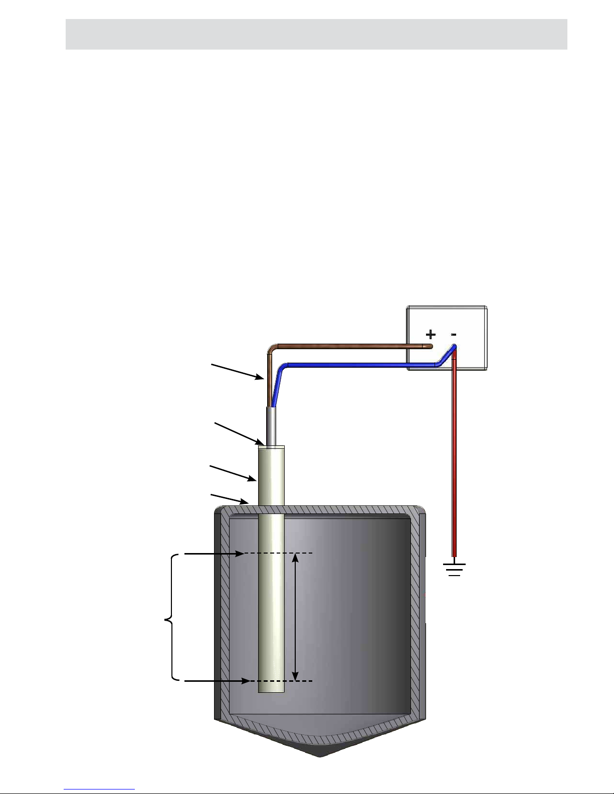
Wichtige Hinweise
Diese Bedienungsanleitung vor der Inbetriebnahme lesen und genau beachten. Die Geräte dürfen
nur von Personen benutzt, gewartet und instand gesetzt werden, die mit der Bedienungsanleitung
und den geltenden Vorschriften über Arbeitssicherheit und Unfallverhütung vertraut sind. Entfer-
nen der Seriennummer sowie Veränderungen am Gerät oder unsachgemäßer Gebrauch führen
zum Verlust des Garantieanspruches. Die Bedienungsanleitung ist aufzubewahren.
Important Note:
Please read carefully and pay full attention to this instruction manual before powering up this
persons who are familiar with the instruction manual and the current rules of safety in the work
place and accident-prevention. Removal of the serial number, changes to the units or improper use
Nota importante:
Estasinstruccionesdeserviciodebenleerseyrespetarseescrupulosamenteantesdelapuestaenmar-
cha.
Sólolaspersonasqueconozcanperfectamentelasinstruccionesdeservicioylasnormasenvigor
sobre seguridad en el trabajo y prevención de accidentes pueden manejar, mantener y poner
el aparato o el uso indebido del mismo provocan la pérdida de la garantía. Las instrucciones de
operación deben conservarse para futuras consultas.
Remarques importantes:
La présente notice est à lire attentivement avant mise en service du matériel. Sa stricte observa-
tion est impérative. Les appareils peuvent être utilisés, entretenus ou réparés uniquement par du
personnel disposant du manuel d’utilisation et des attributions nécessaires en ce qui concerne la
-
tion de l’appareil ou son utilisation inappropriée conduiront à la perte de la garantie. Cette notice
d’utilisation est à conserver pour de futures consultations.
Nota importante:
Vi invitiamo a seguire attentamente queste istruzioni prima di collegare il sensore. Queste appa-
recchiature devono essere usate e messe in funzione da persone competenti, che conoscono le
istruzioni, le norme vigenti di sicurezza e le norme di prevenzione incidenti. Il distacco del numero
della garanzia. Si prega di conservare il manuale di istruzioni per future consultazioni.
© RECHNER 08.2018 - Printed in Germany
Irrtümer und Änderungen ohne vorherige Ankündigung vorbehalten.

3
ITALIANO
ESPAÑOL
FRANÇAIS
ENGLISH
DEUTSCH Wichtige Hinweise Seite 2
Erste Schritte Seite 4
Allgemeine Beschreibung Seite 5
Montage Seite 6
Technische Daten / Elektrischer Anschluss / EasyTeach chart Seite 7
Analogausgang AOUT / Einstellungsbedingungen Seite 8
Einstellungsphilosophie Seite 9
Einstellung Analog MIN Seite 10
Einstellung Analog MAX Seite 11
Reset Seite 12
Testbetrieb Seite 13
Important Note Page 2
First steps Page 18
General Description Page 19
Mounting Page 20
Technical Data / Electrical Connection / EasyTeach chart Page 21
Analogue Output AOUT / Adjustment Conditions Page 22
Adjustment Philosophy Page 23
Adjustment Analogue MIN Page 24
Adjustment Analogue MAX Page 25
Factory Reset Page 26
Test mode Page 27
Nota importante Página 2
Primeros pasos Página 32
Descripción general Página 33
Montaje Página 34
Características técnicas
/ Conexión eléctrica
/
EasyTeach chart Página 35
Analogue Output AOUT / Condiciones de ajuste Página 36
Filosofía de ajuste Página 37
Ajuste de analógica MÍN Página 38
Ajuste de analógica MAX Página 39
Reset Página 40
Modo test Página 41
Remarque importante Page 2
Premières étapes Page 46
Description générale Page 47
Montage Page 48
Caractéristiques techniques / Connexions électriques / Charte EasyTeach
Page 49
Analogue Output AOUT / Conditions d‘étalonnage Page 50
Philosophie d’étalonnage Page 51
Étalonnage Analog MIN Page 52
Étalonnage Analog MAX Page 53
Fonction RESET Page 54
Fonction TEST Page 55
Nota importante Pagina 2
Primi passi Pagina 60
Descrizione generale Pagina 61
Montaggio Pagina 62
Dati tecnici / Collegamento elettrico / EasyTeach chart Pagina 63
Analogue Output AOUT / Condizioni di regolazione Pagina 64
Filosoa di taratura Pagina 65
Regolazione di analogica MIN Pagina 66
Regolazione di analogica MAX Pagina 67
Reset Pagina 68
Test Pagina 69

4
Erste Schritte
Vielen Dank,
dass Sie sich für ein Gerät von RECHNER Sensors entschieden haben. Seit über 50 Jahren hat sich
RECHNER Sensors mit Engagement, Produktinnovationen und bester Qualität eine weltweite Spitzen-
position am Markt erarbeitet.
Symbolerklärungen
Information: Zusätzlicher Hinweis
Achtung: Wichtige Information / Sicherheitshinweis
Handlungsbedarf: Hier ist eine Einstellung oder eine Handlung vorzunehmen
i
und Vollständigkeit.
wortlichen Zustelldienst.
zur Verfügung.
Vor der Installation

5
Allgemeine Beschreibung
-
teelektronik basiert auf unserem patentierten 3-Elektroden-Messprinzip. Die i-Level+ Sonden sind für die
klassischen kapazitiven Sensoren zu vergleichen. Das Messfeld wird durch inaktive Bereiche nach oben
und unten begrenzt.
Eine manuelle Vorauswahl des Kapazitätsbereiches oder einer Grundkapazität ist nicht notwendig. Dies
übernimmt die intelligente Sonde bei der ersten Inbetriebnahme automatisch.
Mit der i-Level+ Sonde lassen sich Analogmessungen zwischen zwei frei wählbaren Punkten innerhalb der
Messstrecke realisieren: „Analog Min“ und „Analog Max“.
Einstellbarer
Analogbereich
Niveau min
und max.
Messstrecke (M)
Sondenstab BE-Anschluss
über Kabelverbindung
Optional Halter für
Prozessanschluß,
Material VA oder AL
Kabel 5 x 0,34 mm²
LED grün
Netzteil

6
Montage
Montage für Sonde mit Temperaturpuffer
BE
KFW-1-ETW
15 mm
D¼D
IBS
M
IB1
1/3D,
min. 50 mm
IBH
Inaktiver Bereich 1 (IB1)
Messbereich (M)
Inaktiver Bereich Schirmung (IBS)
Temperaturpuffer (TP)
Inaktiver Bereich Halterung (IBH)
Messbereich nicht im Bereich von Querschnittsänderungen des Behälters montieren, wie z. B. im Konusbereich. Sonden-
montage mittig oder aussermittig möglich. Um unabhängig vom Schüttkegel zu messen, ist der Einbau bei ¼ Durchmesser
zu empfehlen. Mindestabstand vom Ende der Messstrecke bis zum leitfähigen Behälterdeckel 50 mm.
Funktionserde BE direkt mit
blauer Litze vom Kabel ver-
binden.
TP
Zwischen der blauen Litze (GND) des Anschlusskabels und Schutzleiter (Erdpotential) muss
metallischen Behältern normalerweise über den Prozessanschluss am Sondenkopf gegeben.
Bei nichtmetallischen Behältern und Sonden ohne Anschlusskopf wird diese Erdung direkt mit
der blauen Litze der Sonde vorgenommen. Die Sonde kann auch kopfstehend, also von unten
nach oben montiert werden.
BE
KFW-51(2)-ETW
15 mm
D¼D
IBS
M
IB1
1/3D,
min. 50 mm
IBH
Inaktiver Bereich 1(IB1)
Messbereich (M)
Inaktiver Bereich Schirmung (IBS)
Inaktiver Bereich Halterung (IBH)
Messbereich nicht im Bereich von Querschnittsänderungen des Behälters montieren, wie z. B. im Konusbereich. Sonden-
montage mittig oder aussermittig möglich. Um unabhängig vom Schüttkegel zu messen, ist der Einbau bei ¼ Durchmesser
zu empfehlen. Mindestabstand vom Ende der Messstrecke bis zum leitfähigen Behälterdeckel 50 mm.
Funktionserde BE direkt
mit blauer Litze vom Kabel
verbinden.
DE

7
Technische Daten
Chart
* Soweit zutreffend. Weitere technische Daten: Siehe Datenblatt.
Elektrische Ausführung 4-Leiter DC
Ausgangsfunktion Analog
Betriebsspannung (UB) 15...30 V DC
Zul. Restwelligkeit max. 5 %
Lastwiderstand (RL)
Leistungsaufnahme max. (Ausgänge unbelastet) 0,9 W
Analogausgang 4...20 mA (0...10 V)**
Zul. Umgebungstemperatur -25...+70 °C
-25...+200 °C**
LED-Anzeige Grün
Schutzbeschaltung Eingebaut
Schutzart IEC 60529 IP 67
Norm EN 60947-5-2*
Anschlusskabel 2 m, PVC, 5 x 0,34 mm²
Elektrischer Anschluss
LED grün / Einstellungsfunktion
Einstellung Min.
Einstellung Max.
Werkseinstellung
Elektrischer Anschluss:
DE

8
Analogausgang AOUT
Einstellungsbedingungen
D) =50 ms
Ausgang Reaktionszeit (tR)= 950 ms
Grundsätzlich gilt, dass
-
ausgeführt werden.
Die Sonde wird ohne Einstellung geliefert.
Während dieser Initialisierungszeit ist der analoge Ausgang A = 4 mA (0 V) bei Sonden mit inversem
Ausgang 20 mA (10 V).
Während der Einstellung reagiert der Ausgang A
Ausgangs-Charakteristika
(Werte für Version mit Spannungsausgang in Klammern):
A = 4 mA (0 V) a
A = 8 mA (2,5 V) aANALOG MIN Einstellung aktiv
A = 12 mA (5 V) aANALOG MIN Einstellung in Ordnung
A = 16 mA (7,5 V) aANALOG MAX Einstellung aktiv
A = 20 mA (10 V) aANALOG MAX Einstellung in Ordnung
A = 4 - 20 mA (0 - 10 V) variabel a
Kapazitiver Eingang Kapazitiver Eingang
95%
tRtime
tD
0%
A
5%
tRtime
tD
100% A

9
Der Moduswechsel erfolgt entsprechend des dargestellten Endlos-Zeitdiagramms.
Mit dem grauen ETW-Kabel wird der Moduswechsel aktiviert.
-
HIGH level: UB, LOW level: 0 V
-
punkt.
Einstellungsphilosophie
H
L
3s
0t
8s 13s 18s
MIN MAX RESET Test
Funktion
Doppel Impulse
ON
3s t
8s 13s 18s
f = 1,5Hz f = 3Hz f = 0,4Hz
LED

10
Einstellung Analog MIN
Sonde ist ordnungsgemäß montiert und elektrisch angeschlossen. Versorgungsspannung eingeschaltet.
Mit dem grauen ETW-Kabel wird der Moduswechsel aktiviert.
A 4 mA (0 V) akeine Einstellung oder vorherige Einstellung war nicht erfolgreich.
= 8 mA (2,5 V).
= 12 mA (5 V)
Nach einem Einstellungsfehler (ERROR) nimmt die Sonde den zuletzt gespeicherten Status wieder ein.
H
L
3s
08s t
MIN 20
0
12
8
4
16 A_MIN -OK
t
20
0
12
8
4
16
A_MIN -OK
1,8
sA_MIN -ERROR
t
20
0
12
8
4
16 A_MIN -OK
A_MIN -ERROR
1,8
s
t
(LED blinkt 15 Hz)
Einstellung
Initialisierungsphase: factory settings
(LED blinkt 15 Hz)
Einstellung
Initialisierungsphase: MIN eingestellt
(LED blinkt 15 Hz)
Einstellung
Initialisierungsphase: MAX eingestellt
A
A
A

11
Einstellung Analog MAX
12 mA (5 V) Analog Min erfolgreich eingestellt.
= 16 mA (7,5 V)
= 20 mA (10 V) = Einstellung Analog MAX erfolgreich.
Nach einem Einstellungsfehler (ERROR) nimmt die Sonde den zuletzt gespeicherten Status wieder ein.
H
L
8s
013s t
MAX 20
0
12
8
4
16
MAX -ERROR
t
20
0
12
8
4
16
MAX -OK
1,8s
t
20
0
12
8
4
16
MAX -OK
1,8
sMAX -ERROR
t
(LED blinkt 15 Hz)
Einstellung
Initialisierungsphase: factory settings
(LED blinkt 15 Hz)
Einstellung
Initialisierungsphase: MIN eingestellt
(LED blinkt 15 Hz)
Einstellung
Initialisierungsphase: MAX eingestellt
A
A
A

12
Reset
Man kann die Sonde jederzeit auf Werkseinstellungen (Reset) zurücksetzen.
= 4 mA (0V), Reset erfolgreich.
H
L
13s
018s t
Reset 20
0
12
8
4
16
t
20
0
12
8
4
16
t
20
0
12
8
4
16
t
Initialisierungsphase: factory settings
Initialisierungsphase: MIN eingestellt Initialisierungsphase: MAX eingestellt
A
A
A

13
Testbetrieb
-
gang wie in den nachstehenden Diagrammen dargestellt verhält. Damit kann die Installation der Sonde
überprüft werden.
Aktivierung Testbetrieb:
-
Status wieder ein.
H
L
018s t
20
0
12
8
4
16
t
20
0
12
8
4
16
t
20
0
12
8
4
16
t
(LED blinkt, f = 0,4 Hz)
Initialisierungsphase: factory settings
Initialisierungsphase: MIN eingestellt Initialisierungsphase: MAX eingestellt
(LED blinkt, f = 0,4 Hz) (LED blinkt, f = 0,4 Hz)
A
A
A

14
bitte direkt an unseren Service.
Wartung, Instandsetzung, Entsorgung

15

16

17
EN
Table of contents
Important Note Page 2
First steps Page 18
General Description Page 19
Mounting Page 20
Technical Data Page 21
Electrical Connection Page 21
EasyTeach Chart Page 21
Analogue Output AOUT Page 22
Adjustment Conditions Page 22
Adjustment Philosophy Page 23
Adjustment Analogue MIN Page 24
Adjustment Analogue MAX Page 25
Factory Reset Page 26
Test Mode Page 27

18
First steps
Thank you,
leadership position with commitment, product innovation and quality.
Symbols
Information: Additional note
Caution: Important note / safety note
Need for action: An action or an adjustment is necessary
i
damage.
Before installing

19
General description
has its evaluation electronics integrated in the probes head is based on our patented 3 electrode measuring
the 3rd electrode is integrated in the probe. In this case the container does not belong to the measurement.
end.
It is not necessary to make a manual pre-selection of the capacity range or of a basic capacity as this is
automatically done by the i-Level+ probe during the initial setup.
measuring range with 2 free selectable points
„ANALOGUE MIN“ and „ANALOGUE MAX“.
Adjustable
analogue Area
Level MIN and
MAX
Measuring range (M)
Probe rod BE-connection via
cable connection
Optional holder for
connection head,
material VA or AL
Cable 5 x 0,34 mm²
LED green
BE (function earth)
Power Supply

20
Mounting
It is mandatory to have a galvanic connection between the blue (GND) wire and the protective
wire (potential earth)! With metal containers the function earth (BE-conncetion) is normally made
through the threading of the probe to the metal container. With non-metal containers and probes
without connection heads the connection to this earth is made by means of a direct cable con-
Mounting with temperature buffer
BE
KFW-1-ETW
15 mm
D¼D
IBS
M
IB1
1/3D,
min. 50 mm
IBH
Non-active range 1 (IB1)
Measuring area (M)
Non-active range shield (IBS)
Area temperature buffer (TP)
Non-active range holder (IBH)
Do not mount the measuring range in the area of the container with changes in the cross section, like the bottom cone of the
container. The probe can be mounted in the centre of the container or just off to one side. For a measurement to be independent
of the lling cone, we recommend that the probe be mounted at ¼ of the diameter. The minimum distance between the end
of the measuring range and the container’s lid is 50 mm.
Connect the BE (function earth)
direct to the blue wire of the
cable.
TP
BE
KFW-51(2)-ETW
15 mm
D¼D
IBS
M
IB1
1/3D,
min. 50 mm
IBH
Connect the BE (function earth)
direct to the blue wire of the
cable.
EN
Non-active range 1 (IB1)
Measuring area (M)
Non-active range shield (IBS)
Non-active range holder (IBH)
Do not mount the measuring range in the area of the container with changes in the cross section, like the bottom cone of the
container. The probe can be mounted in the centre of the container or just off to one side. For a measurement to be independent
of the lling cone, we recommend that the probe be mounted at ¼ of the diameter. The minimum distance between the end
of the measuring range and the container’s lid is 50 mm.
Table of contents
Languages:
Other Rechner Sensors Measuring Instrument manuals