reci R20 User manual

CO2RF Laser R20
Instruction Manual
Zhejiang Reci Laser Technology Co., Ltd.

浙江热刺激光技术有限公司
Zhejiang Reci Laser Technology Co., Ltd.
- 1 -
Content
Chapter 1 Product Introduction ............................................................................................ - 3 -
1.1 General Information ................................................................................................. - 3 -
1.2 Description ................................................................................................................ - 3 -
Chapter 2 Specifications ....................................................................................................... - 3 -
2.1 Laser System Specification ...................................................................................... - 3 -
2.2 Integrated RF Power Supply Specification .............................................................. - 4 -
2.3 DC Power Supply Specification ............................................................................... - 4 -
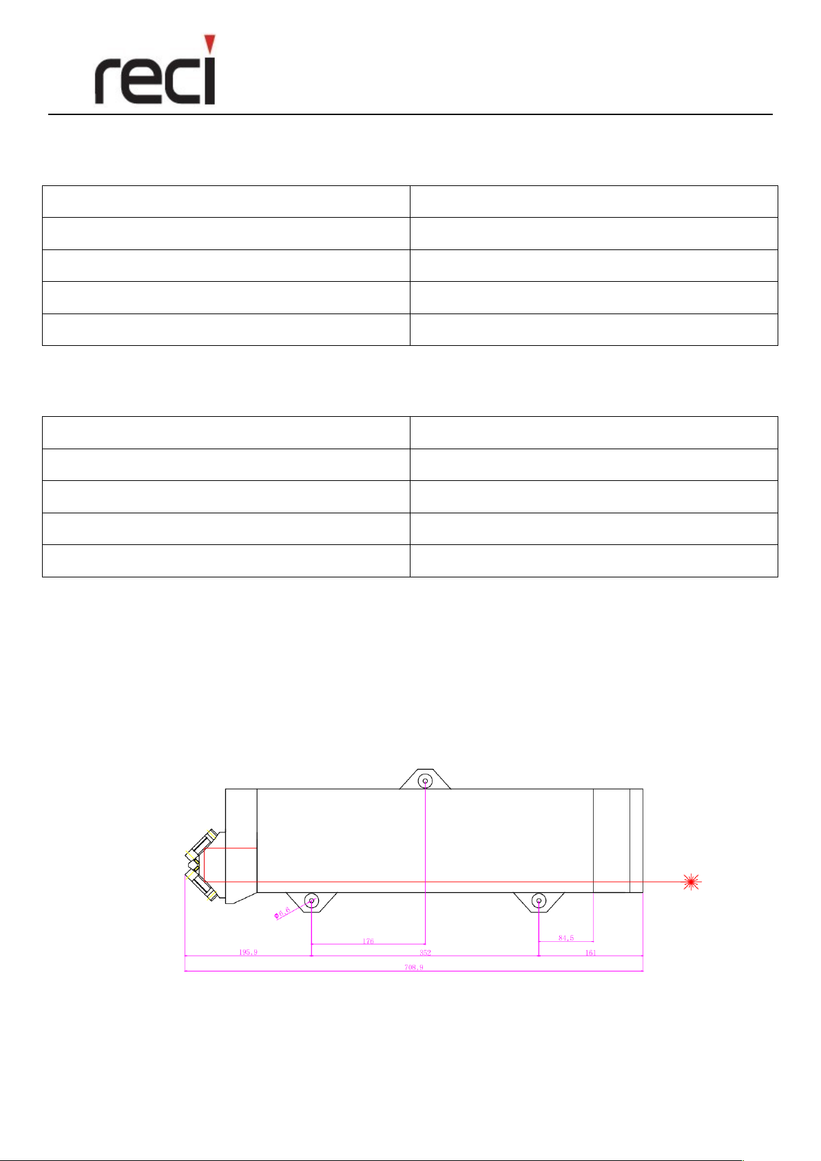
2.4 Fixing locations ........................................................................................................ - 4 -
2.5 Technical Information ............................................................................................... - 5 -
2.6 Environmental Specification .................................................................................... - 5 -
2.7 Coolant Specification ............................................................................................... - 5 -
2.8 Nitrogen Specification .............................................................................................. - 7 -
Chapter 3 The Installation .................................................................................................... - 8 -
3.1 Installation ................................................................................................................ - 8 -
Chapter 4 Pin Connection Description ............................................................................... - 10 -
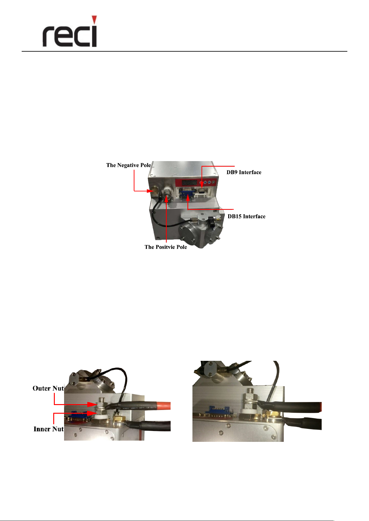
4.1 Communication Interface ....................................................................................... - 10 -
4.2 Functions Reequipment .......................................................................................... - 11 -
4.3 Common Problem ................................................................................................... - 11 -
4.4 Serial Port Specification ......................................................................................... - 12 -
Chapter 5 Operating Instruction ......................................................................................... - 15 -

浙江热刺激光技术有限公司
Zhejiang Reci Laser Technology Co., Ltd.
- 2 -
5.1 Button Description .................................................................................................. - 15 -
5.2 Specific details for operation .................................................................................. - 15 -
5.3 Test Status of RF laser .......................................................................................... - 16 -
5.4 Normal Problem ..................................................................................................... - 16 -
Chapter 6 Duty Cycle Description ...................................................................................... - 17 -
6.1 Power Description .................................................................................................. - 17 -
Chapter 7 Maintenance ....................................................................................................... - 17 -
7.1 General Cleaning .................................................................................................... - 17 -
7.2 Replacing cooling water periodically ..................................................................... - 17 -
Chapter 8 Others ................................................................................................................. - 18 -

浙江热刺激光技术有限公司
Zhejiang Reci Laser Technology Co., Ltd.
- 3 -
Chapter 1 Product Introduction
1.1 General Information
Before installing or operating R20 RF laser, all personnel must be familiar with the Health and Safety issues
covered in the Safety Instructions and Precautions manual.
1.2 Description
The R20 RF laser assembly consists of sealed cavity, a water-cooling system, and a finely turned optical
correction system.
Figure 1 Laser Introduction
Chapter 2 Specifications
2.1 Laser System Specification
Laser tube
Sealed cavity, RF excited, diffusion cooled
Wavelength
10.6μm (9.3μm optional)
Power range Rated (Watts)
20 - 150 W
Peak Power (Watts)
300 W
PO Power
100 W
Excitation frequency
81 MHz
Expected tube lifetime
(This is an expectation not a guaranteed figure)
>20,000 hrs
Energy
10 - 200 mJ
Typical Power Stability (at start up)
<± 3.5%
External Dimensions
708 x 160 x 152 (mm)
Weight
28.5 Kg

浙江热刺激光技术有限公司
Zhejiang Reci Laser Technology Co., Ltd.
- 4 -
Table 1 Laser System Specification
2.2 Integrated RF Power Supply Specification
Output power peak
3 kW
DC Input
50V+/-1V (imax=70A)
Pulse Width Range
0 – 520 μs
Frequency
1 – 100 kHz (Maximum)
Duty Cycle (Range)
4—52%, 4—60%
Table 2 RF Power Supply Specification
2.3 DC Power Supply Specification
Output Voltage
50V DC +/- 1V
DC Output (Average)
60 A
DC Output (Peak)
100 A
Output Power (Maximum)
5 kW
Average Power at 50% load
3 kW
Table 3 DC Power Supply Specification
2.4 Fixing locations
Make sure the correct orientation of the RF laser while installing. And the laser output is not allowed
upwards. If it is mounted vertically in this orientation, the optical surface inside the optical assembly tends
to accumulate dust, which will shorten the life of the optical assembly, especially in dusty environment.
Installation drawing:

浙江热刺激光技术有限公司
Zhejiang Reci Laser Technology Co., Ltd.
- 5 -
2.5 Technical Information
The technical information for the output beam is shown in the table below.
M² (K)
<1.2 (>0.833)
Beam diameter
8mm ± 0.5mm, at laser output optic
Beam Divergence
<2mrad, full angle far field
Beam Ellipticity
<1.2:1
Pointing Stability
<0.25mrad (Half angle)
Polarsation
Linear parallel to base
Table 4 Output Beam Specification
Note: In order to protect the laser, please do not cut high reflection material, such as mirror metal.
2.6 Environmental Specification
Ambient working temp
3 - 42 °C
Storage temperature
-10 - +70 °C
Humidity (Non-condensing)
10 - 85% relative humidity
Table 5 Environmental Specification
2.7 Coolant Specification
2.7.1 The specification for the coolant
(1) R300 Laser requires a liquid coolant source to operate correctly. The specification for the coolant is as
follows.
Coolant flow rate (Minimum)
12 L/min
Coolant flow rate (Recommended)
16 L/min
Coolant Pressure(max)
4.0 bar
Refrigeration Capacity requirement
>3.2 kW
Connections
14mm outer diameter tube
Coolant Temperature
25 - 27 °C
Table 6 The coolant specification
Note: Optimum at 20°C- Increased temperature affects the power of the laser and shortens its life.

浙江热刺激光技术有限公司
Zhejiang Reci Laser Technology Co., Ltd.
- 6 -
(2) Water Cooling Pipe Installation Diagram
Figure 2 Water Cooling Installation
(3) Water cooling Circuits Precautions
Please be noted as below.
l The cooling circuit material must be selected to avoid corrosion.
l In order to avoid blockage caused by oxidation, the cooling circuit are not recommended to be made of
aluminum, zinc, mild steel or cast iron.
l The cooling circuit are recommended to be made of stainless steel, copper, copper alloy and opaque
plastic pipe, etc.
l It's better to recommend an opaque pipeline system to avoid bacteria or moss in the pipeline.
l The temperature of cooling liquid must be above dew point to avoid condensate on the inner assembly.
The high purity nitrogen is needed to protect the laser system before cooling liquid.
l Before shipment or storage, drain off the contaminated cooling liquid.
2.7.2 Cooling Water Specification
To endure trouble-free operation of the laser and to prevent corrosion in the cooling circuit, the following
requirements must be complied with:
(1) Quality of the cooling water
Use only de-mineralized, de-ionized or distilled water with an anti-corrosion addictive. Ensure that the
following limits on the water quality are met:
Conductivity
< 1000 μS/cm
Total Hardness
< 10 ppm
pH value of the water
7 – 8.5
Bacterial Level
<1000 cfu/ml
Table 7 Water Quality Requirements

浙江热刺激光技术有限公司
Zhejiang Reci Laser Technology Co., Ltd.
- 7 -
The pH value, conductivity and dissolved levels can be measured with a portable meters and the bacteria
level can be checked with a test kit – For more information, please contact the local Reci Sales and Service
Office.
(2) Suspended Particles
To remove particulate contamination, a filter with a pore size of 100um must be used. The filter should be
located as close as possible and in line with the cooling water inlet of the laser head and should be regularly
checked for blockage and cleaned or replaced when necessary. This is particularly important after bacterial
growth has been detected and treatment applied.
(3) Corrosion and Germ Formation Inhibitors
The corrosion and germ formation inhibitors depend on the total of the cooling water circuit to be used.
(4) Contaminated Cooling Water
If the cooling water is contaminated with bacteria or has been treated with other chemicals, it will be
necessary to clean the cooling circuit.
(5) Frost Protection
If the cooling system or chiller which supplies the cooling for the laser system is located in the area where
the temperature may be below 0°C, then the cooling water circuit must be equipped with a winter proof
heating tank to prevent the cooling water temperature which drops below 15°C.
2.8 Nitrogen Specification
The inner laser system must require high purity nitrogen for two purposes as below,
(1) To prevent the ingress of particles and moisture from contaminating the optical system and circuit board.
(2) To prevent the ingress of particles and moisture from dewing of the optical system and circuit board.
Nitrogen Purity Specification
Pressure
1.5-3 psi (0.1-0.2 bar)
Nitrogen Purity Grade
≥ 4.6 (Above 99.996% Purity)
Table 8 Nitrogen Purity Specification
Nitrogen Installation Instruction

浙江热刺激光技术有限公司
Zhejiang Reci Laser Technology Co., Ltd.
- 8 -
Figure 3 Nitrogen Input
Note
(1) Please input nitrogen around 3 minutes to fill the inside before turning on the laser
(2) To ensure the nitrogen at a positive pressure during laser normal operation.
Chapter 3 The Installation and Options
3.1 Installation
3.3.1 Connecting the DC Supply Cables
Figure 4 DC Supply Connection
(1) Please connect the positive pole of the DC power supply to the respective positive pole of the laser as
shown in the figure, and connect the negative pole of the DC power supply to the negative of the laser.
(2) Extremely, the DC power supply should be on and checking with the multimeter to distinguish between
the positive and negative poles of the power supply before installation.
(3) Generally, the red cable means the positive, and the black cable means the negative.
Note
(1) Please note the orientation of cable before installing and refer to the below figure to avoid short circuit.
Figure 5 Correct cable installation diagram Figure 6 Wrong cable installation diagram
(2) When connecting the DC power supply cable to the laser’s positive filtering connector, please note that
the inner nut can be tightened by hand to protect the internal components. Then use a wrench to clamp

浙江热刺激光技术有限公司
Zhejiang Reci Laser Technology Co., Ltd.
- 9 -
the inner nut during tightening outer nut to avoid the rotation. And use two wrenches to prevent
damaging the connector shown below.
Figure 7 Correct installation diagram Figure 8 Wrong installation diagram
3.1.2 Installing DB15 and DB9
Installing DB15 and DB9 (Only for Communication), please refer to pin definition in next Chapter.
3.1.3 The Usage Time
When DC power supply turning on, the laser will be start with a short beep normally. The usage time will be
displayed 10 seconds later after startup. If there is a problem, an alternate alarm will occur and the alarm
code will be displayed. Please refer to FAQ in Operations chapter.
3.1.4 Self-testing
It will take 20 seconds for self-testing, then the interface will change from the usage time to parameters
display. (Note that low power laser will be emitted during self-testing.) The normal standby state will be
ready if no alarm. The parameters will be scrolling down the screen as below.
1.xxxx
Condensation parameter 1
2.xxxx
Condensation parameter 2
3.xxxx
Coolant plate temperature
4.xxxx
DC voltage
5.xxxx
Preionization value
6.xxx
Humidity
p.xxx
Duty Cycle
f.xxx
Frequency
Table 9 The Self-testing
3.1.5 The Enable Signal
After the standby, the laser will be ready. PWM signal must be inputted firstly with 10ms stop. Then Enable
signal will make the laser working normally.

浙江热刺激光技术有限公司
Zhejiang Reci Laser Technology Co., Ltd.
- 10 -
Chapter 4 Pin Connection Description
Figure 9 Pin Connection Description
4.1 DB9 and DB15 Connection Details
(1) Pin DB9 Connection Details
DB9 Pin No
Function
Parameters
Brief Description
1
GND (Ground)
Serial port line
2
Tx
Baud rate: 19200,
Data bits:8
Stop bits:1
Parity: not
Tx
3
Rx
Baud rate: 19200,
Data bits:8
Stop bits:1
Parity: not
Rx
4
-
-
-
5
6
7
8
Can_H
Baud rate:1 Mhz
Can Port: H
9
Can_L
Baud rate:1 Mhz
Can Port: L
Table 10 Pin DB9 Connection Details

浙江热刺激光技术有限公司
Zhejiang Reci Laser Technology Co., Ltd.
- 11 -
(2) Pin DB15 Connection Details
DB15 Pin No
Function
Parameters
Brief Description
1
2
CEN-
5V 10~15mA
Enable Cathode
3
CEN+
5V 10~15mA
Enable Positive
4
CMOD+
5V 10~15mA
PWM positive, 1~100
kHz Square wave, Duty
cycle 3~60%, Avoid
2.2~4kHz.
5
CMOD-
5V 10~15mA
PWM Cathode
6
7
8
Interlock+
Interlock positive
Interlock+ must be low
to enable the system
9
10
-
-
-
11
12
-
-
-
13
-
-
-
14
-
-
-
15
Interlock-
Interlock cathode
Table 11 Pin DB15 Connection Details
4.2 Communication Interface
The communication interface is the DB9, which has 2 kinds of communications, Rs232 and CAN
respectively. The communication is mainly about the parameters relating to core components inside, only for
reference to connect to control system. If communication is not needed, there will be no connection and it
will not affect the normal working of the laser.
4.3 Functions Reequipment
4.3.1 PWM
The power will be adjusted by the duty cycle, and the frequency is from 1 to 100kHz (Please avoid the
frequency from 2-4kHz with noise.). The range of duty cycle is from 4% to 52%, and the current must be
within 10-15mA. Otherwise, it will be deformed due to insufficient current.

浙江热刺激光技术有限公司
Zhejiang Reci Laser Technology Co., Ltd.
- 12 -
4.3.2 The Enable
It is the signal for laser on or off. When enable pin reaches 5V, the laser will be output. Whereas no laser
when enable pin is 0V. The enable time between on and off is recommended to be more than 20ms.
4.4 Common Problem
4.4.1 Disconnected communication
(1) Checking the communication settings, especially Baud rate. The simulation software is recommended to
testing the connection.
(2) Please check if the cable is connected correctly or not.
4.4.2 No Laser
(1) Please check if the cable is connected correctly or not.
(2) Please check if the PWM working normally or not. The oscilloscope is recommended for testing. PWM+
can be connected to the positive pin of oscilloscope, and PWM- to the negtive pin of oscilloscope. Then
check whether the waveform is output based on the setting. If it is not square wave or the voltage of
square wave is being low, the current is proved to be insufficient.
(3) Please check whether the voltage of the enable signal remains 5V. If the voltage is low, it is proved a
short circuit or insufficient current.
4.5 Serial Port Specification
4.5.1 RS232 connecting to communication
RS232 is used for hardware interface. Please use the dedicated connection cable provided by us to connected
the communication interface.
4.5.2 RS232 Settings
RS232 Settings: please input 19200 for Baud, 8 for date bits, 1 for stop bits and no parity.
4.5.3 Protocol Instruction
The protocol is available to check the working state of laser. The main mode is that a checking signal will be
sent by the control system, such as computer. In response to the command, the laser will feedback its state.
Protocol Details
Computer ---> Laser 6E 61 31 6F 6F 6F
Laser ---> Computer
Date
Byte 1: 0xee (Start)
Byte 2: 0x00
Byte 3: 0x00
Byte 4: 0x00

浙江热刺激光技术有限公司
Zhejiang Reci Laser Technology Co., Ltd.
- 13 -
Byte 5: 0x00
Byte 6: 0x00
Byte 7: 0x00
Byte 8: 0x00
Byte 9: 0xa0 (Date Start)
Byte 10: xx(status:1, Normal 2,Over-temperature.3,Interlock disconnect.
4, Over-voltage.5,Dew Formation .6,Over-reflect.7, Initializing failed.)
Byte 11: xx(Forward power High)
Byte 12: xx(Forward power Low)
Byte 13: xx(Reflect power High)
Byte 14: xx(Reflect power Low)
Byte 15: xx(Input duty ratio High)
Byte 16: xx(Input duty ratio Low)
Byte 17: xx(Input freq High)
Byte 18: xx(Input freq Low)
Byte 19: xx(Dew Para High)
Byte 20: xx(Dew Para Low)
Byte 21: xx(-)
Byte 22: xx(Temperature)
Byte 23: xx(Voltage)
Byte 24: 0x22
Byte 25: xx(Preionization High)
Byte 26: xx(Preionization Low)
Byte 27: 0x00
Byte 28: 0x00
Byte 29: 0x00
Byte 30: 0x00
Byte 31: 0x00
Byte 32: 0x00
Byte 33: xx(Run time x 1000)
Byte 34: xx(Run time x 100)
Byte 35: xx(Run time x 1)
Byte 32: 0xff(Stop)
Note: For example: Preionization =Preionization High x 100 + Preionization Low

浙江热刺激光技术有限公司
Zhejiang Reci Laser Technology Co., Ltd.
- 14 -
Figure 10 Serial Port Display

浙江热刺激光技术有限公司
Zhejiang Reci Laser Technology Co., Ltd.
- 15 -
Chapter 5 Operating Instruction
5.1 Button Description
Figure 11 Button Description
There are four buttons on the laser, including Up, Down, Back, OK. Up and Down is for adjusting the parameters. Back is
for returning to the previous step. OK is for authorizing the change or switch on the laser while hand-testing.
5.2 Specific details for operation
5.2.1 Cancel Time Operation
(1) Press the OK button to enter the password setting, then P0000 will be shown on the display. Here the
Back button is used to select the digit. It is noted that the currently changed digit will be brighter than the
others.
(2) Press the Up and Down buttons to modify the value.
(3) After modifying, press the OK button and 0 will be shown on the display to prove the correct inputting.
Then press the OK button to enter the standby state.
(4) The time limit will be cancelled after restarting the laser. And it will be used indefinitely. (The laser will
be locked due to repeatedly entering the wrong password after a certain number of times.)
5.2.2 Laser Testing State
(1) Press the OK button to enter the password setting, then P0000 will be shown on the display. Here the
back button is used to select the digit. It is noted that the currently changed digit will be brighter than the
others.
(2) Press the Up and Down buttons to modify the value to 1,000.
(3) After pressing the OK Button, F-000 will be shown on the display for frequency setting. The frequency
range can be adjusted from 0 to 100. (For example, F-10 means the frequency of PWM is 10 kHz.)
(4) P-xxx will be shown on the display for duty cycle setting after pressing the OK button. The duty cycle
range is 0~52%. (For example, P-10 means the duty cycle of PWM is 10%)
(5) The laser testing state will be ready after pressing the OK button. Then press it again for laser on and
release it for laser off. 8888 will be shown after long pressing the Back button for returning successfully.
Note: In the testing state, the laser cannot be controlled by the PWM and the enable directly. The testing
state can be cancelled after long press the Back button more than 5 seconds and 8888 will be appeared on
the display to prove returning successfully.

浙江热刺激光技术有限公司
Zhejiang Reci Laser Technology Co., Ltd.
- 16 -
5.3 Normal Problem
5.3.1 Wrong Password
If failing to enter the password interface after pressing the OK button. This is because the wrong password
has been inputted too many times, which causes inputting function locked. It will be available after one hour.
5.3.2 No laser beam after pressing the OK button.
(1) The button may be damaged due to pressing by the nail for long time. So, it is recommended to press it
with fingertips.
(2) Pressing time is too short to trigger the switch. In this way, long press the OK button in the testing state 2
till the numbers on the display disappeared.
Error Code
Descriptions
E 2
The machine temperature is too high.
E 3
Interlocked and disconnected.
E 4
Voltage error caused by power supply (Less than
48V or More than 52V)
E 5
Condensations
E 6
Over-reflection
E 7
Laser Pre-detection Fault (Please turn off the power
and restarting. If it is invalid repeatedly, please
contact us. )
E 8
Trial Time Expires
Table 11 Error Code
5.3.3 Password Input for Trial Time
(1) Press the OK button to enter the password setting, then P0000 is shown on the display. Press the Back
button to select the digit to be changed. The currently changed number will be brighter than the others.
(2) Select the digits which needs to be changed, then press UP or Down button to modify the value to 3000.
(3) After pressing the OK button, H-6 is shown on the display, which means the unlock time. Users can
press UP or Down to change the unlocking time. H-6, H-12 and H-18 means separately unlocking time
can be 6 months, 12 months and 18 months.
(4) After pressing the OK button, F0000 is shown on the display. Please contact us to get the respective
password for extending the usage time. If the password for 18 months, the laser will be no time limit. If
the password for 6 months, then users need to get a new one when the alert will be pop-on after 6 months
using. If the password is wrong, E-8 will be shown on the display. The password will be successful when
8888 is appearing on the display before restart.

浙江热刺激光技术有限公司
Zhejiang Reci Laser Technology Co., Ltd.
- 17 -
Chapter 6 Duty Cycle Description
6.1 Power Description
The laser power is mainly adjusted by the duty cycle. (For example, if the frequency is firmly 5Kha, 280w
require to adjust the duty cycle to 52%.)
Figure 12 (Power/Duty Cycle Chart) Watt
Note: The diagram is only for reference.
Chapter 7 Maintenance
7.1 General Cleaning
Please always ensure that the system is turned off and isolated from the main power supply before
attempting any cleaning procedures. The external surfaces of the system can be cleaned with a mild
detergent, such as alcohol.
7.2 Replacing cooling water periodically
The cooling water must be replaced periodically. Otherwise it will cause damage to the internal waterway
system of the laser.

浙江热刺激光技术有限公司
Zhejiang Reci Laser Technology Co., Ltd.
- 18 -
Chapter 8 Others
In case of avoiding the interference caused by the current, it is recommended that the shielded cable should
be used as the control cable.
Table of contents
Other reci Measuring Instrument manuals
Popular Measuring Instrument manuals by other brands

HP
HP 400E Operating and service manual

Pulsar
Pulsar Pulsarguard 201 Series instruction manual

E Instruments
E Instruments E4500 operating & maintenance manual

Maico
Maico MA 42 operating instructions

Perfect 10 Satellite Distributing
Perfect 10 Satellite Distributing Birdog manual

Fizoptika
Fizoptika VG910H Information guide

Siemens
Siemens SITRANS FEC920 quick start guide

Lambrecht
Lambrecht 8126 X81 operating instructions

FixPosition
FixPosition Vision-RTK 2 Starter Kit quick start guide

techem
techem Geometry TE1 installation instructions

LaMotte
LaMotte DC1500 FLUORIDE manual

PCE Health and Fitness
PCE Health and Fitness CMM 8 user manual