Recovery Pump 737R RPX User manual

Massage System
Model 737R (RPX)
User Manual
Foot Health International Limited
PO Box 13540
Tauranga
www.recoverypump.co.nz
L98005H1R-A


RecoveryPump®Model 737R (RPX) User Manual
Table of Contents
1. Important Safety Information........................................................1
2. RecoveryPump®Specifications and Dimensions........................3
3. Labels .............................................................................................3
4. Indications for Use ........................................................................5
5. About RecoveryPump®..................................................................5
6. Components of the RecoveryPump®System ..............................9
7. How to Operate the RecoveryPump®System............................12
8. Maintenance and Storage ...........................................................27
9. Troubleshooting ..........................................................................29
10. Warranty and Contact Information .............................................30
11. EMC Manufacturer Declarations.................................................31
L98005H1R-A


RecoveryPump®Model 737R (RPX) User Manual
1. Important Safety Information
Read all instructions before using the RecoveryPump®system for the first time.
!
Warning:
•This system is intended for use by people in good health. This system
is not recommended for people who have heart problems, or vascular
problems, have a condition requiring the use of any medical device, or
have any condition that might affect their normal well-being.
•If you are, or may be, pregnant, consult with your physician before use.
•Do not use this system over insensitive or numb areas, or in the
presence of poor circulation. Do not use if you have been diagnosed
with blood clots, deep vein thrombosis or phlebitis. This system should
not be used over swollen or inflamed areas or skin eruptions. Do not
use in the presence of unexplained calf pain.
•Consult your physician prior to use.
Safety Warnings and Precautions
!
Warning:
•Explosion Hazard: Do not use the RecoveryPump®system in the
presence of flammable gases, including flammable anesthetics.
•Electric Shock Hazard: Do not allow liquid to enter any part of the
RecoveryPump®
console. Do not immerse. To clean, follow instructions
in Chapter 8 - Maintenance and Storage.
Electric Shock Hazard: To prevent electric shock, do not open the
console. Do not attempt to service the console yourself. All
maintenance tasks should be performed only by RecoveryPump®
trained and authorized service personnel. Service by unauthorized
personnel shall void any warranty.
•Stop treatment in case of any change of the RecoveryPump®system
performance.
•Use the RecoveryPump®console only with RecoveryPump®system
garments and accessories.
•Do not modify any part of the RecoveryPump®system.
•The equipment should not be used adjacent to or stacked with other
equipment. In case adjacent or stacked use is necessary, the
equipment should be observed to verify normal operation in the
configuration in which it is used.
•The RecoveryPump®system includes small parts. To avoid choking,
do not swallow, and keep away from children and pets.
L98005H1R-A 1

RecoveryPump®Model 737R (RPX) User Manual
Caution:
•Do not operate the RecoveryPump®system during transit.
•Do not store or transport the RecoveryPump®system beyond the
specified temperature, humidity, and atmospheric pressure ranges (see
Chapter 8 - Maintenance and Storage).
•Do not use the RecoveryPump®system beyond the specified
temperature range: 10 to 30°C (50 to 86°F).
•Do not use the RecoveryPump®system beyond the specified humidity
range: 30%rH - 75%rH, non-condensing.
•Use the RecoveryPump®system up to 3000m above mean sea level.
•To prevent any damage to the RecoveryPump®system, keep it away
from dust, lint, and dirt. Keep away from sources of heat or moisture.
•To prevent any damage to equipment, use only accessories,
detachable parts and materials described in this user manual.
•While in use, place the console on horizontal firm surface only. Do not
place the console on bed, blanket, mattress, pillow, or soft furniture.
Do not cover the console.
•Use only accessories approved by the manufacturer (Mego Afek AC
Ltd.). Other accessories may damage the system or interfere with
system function.
•The equipment is to be installed and put into service according to the
EMC information provided in Chapter 11 - EMC Manufacturer
Declarations.
•Portable and mobile RF communication equipment might affect the
equipment.
2 L98005H1R-A

RecoveryPump®Model 737R (RPX) User Manual
2. RecoveryPump®Specifications and Dimensions
Model: 737R, appliance coupler, transportable, rated: 100-240 VAC, 50-60 Hz
Type of protection against electric shock Class II
Degree of protection against electric shock Type BF
Degree of protection against ingress of water IP21
Degree of safety of application in the
presence of a flammable anesthetic mixture
with air or with oxygen or nitrous oxide
Equipment not suitable for use in the
presence of a flammable anesthetic mixture
with air or with oxygen or nitrous oxide
Mode of operation Continuous
Treatment duration 15 minutes to 90 minutes
Environmental Conditions Normal: 10-30°C, 30-75% rH, 700-1060 hPa
Pressure Range 20 mmHg to 100 mmHg
Size 22 cm × 17 cm × 13 cm (8.6" × 6.7" × 5.1")
Weight 1.5 kg (3.3 lbs.)
3. Labels
The following labels and symbols appear on the console, garments and/or packaging.
Symbol Description Location
IP21 Degree of protection against
ingress of water On base of console
Read instructions before use On base of console
Read instructions before use On garment label
Level of protection type BF
equipment On base of console
Double insulation On DC power adapter
Direct current On base of console
Manufacturer's name and address On garment label & on base of
console
Date of Manufacture On base of console
L98005H1R-A 3

RecoveryPump®Model 737R (RPX) User Manual
Symbol Description Location
Separate collection for waste
electrical and electronic
equipment
On base of console
Serial number of the console On base of console
Fragile, handle with care On package
Keep dry On package
This side Up On package
Keep away from sunlight On package
Transportation & storage humidity
limitation On package
Transportation & storage
atmospheric pressure limitation On package
Transportation & storage
temperature limitation On package
"ON" (power) On Main Switch
"OFF" (power) On Main Switch
Do not wash On garment tag
Do not dry-clean On garment tag
Do not tumble dry On garment tag
Do not bleach On garment tag
Do not iron On garment tag
4 L98005H1R-A

RecoveryPump®Model 737R (RPX) User Manual
4. Indications for Use
The RecoveryPump®powered inflatable tube massager is indicated for the
temporary relief of minor muscle aches and pains, and for temporary increase
in circulation to the treated areas in people who are in good health. The
RecoveryPump®simulates kneading and stroking of tissues by using an
inflatable garment.
5. About RecoveryPump®
RecoveryPump®is a massage system intended for use by people in good
health. As noted above, RecoveryPump®simulates the kneading and stroking
action of manual massage by use of an inflatable garment that fills and
deflates, applying a directional compress-and-release massage. This soothing
massage action temporarily increases circulation in the areas to which the
garment is applied, and temporarily relieves muscle aches and pain caused by
fatigue or overexertion.
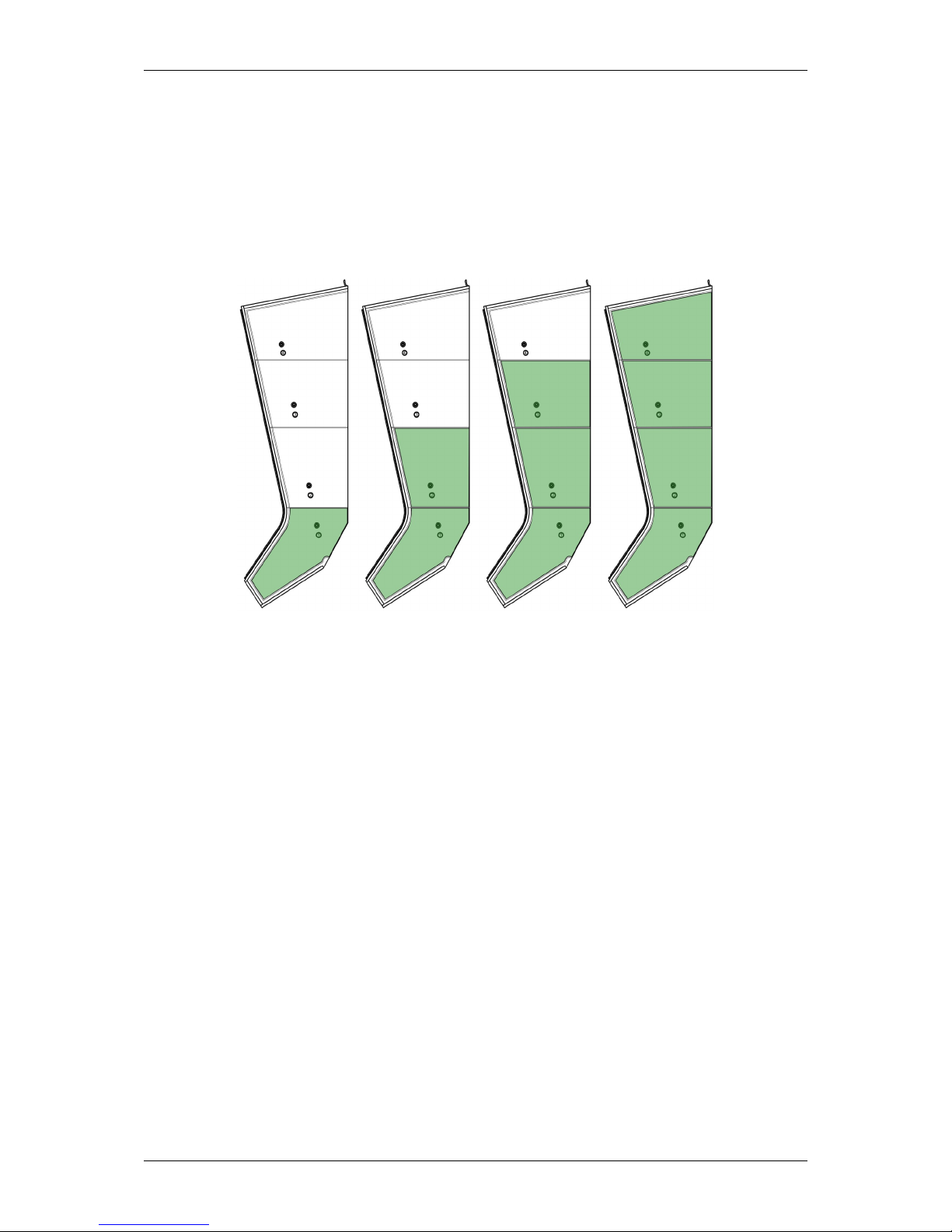
The RecoveryPump®Massage Cycle
The RecoveryPump®console takes air from the room environment and sends
it through hoses into four individual air chambers inside the RecoveryPump®
garment.
The air chambers in the RecoveryPump®garment are specially designed to
overlap each other, for fluent, comfortable massage, without gaps. You can
adjust the pressure level of the massage, treatment time, hold time, and the
pause time in between inflation cycles.
The RecoveryPump®console can operate one or two garments
simultaneously, so you can use it on both your legs, arms, or hips at the
same time, for a relaxing massage.
RecoveryPump®has six different treatment programs:
•Recovery (Sequential cycle mode)
•Pre-Train (Sequential cycle mode)
•Rehab (ISO - Isolation cycle mode)
•Three Custom Programs (Sequential or ISO cycle mode)
These programs are described in the following sections.
L98005H1R-A 5

RecoveryPump®Model 737R (RPX) User Manual
The Recovery and Pre-Train Programs
The Recovery and Pre-Train programs use the Sequential cycle mode that
applies a directional massage, starting at the base of the treated area, and
progresses upwards towards the torso and then releases (see Figure 1).
This applies a deep, slow massage.
•The Recovery program is recommended for use after a workout.
•The Pre-Train program is recommended for use before a workout.
Figure 1 - Sequential Cycle Mode
6 L98005H1R-A

RecoveryPump®Model 737R (RPX) User Manual
The Rehab Program
The Rehab program uses the ISO cycle mode that applies a directional
massage to a smaller area. Only two adjacent cells in the garment are
inflated. The first cell inflates, and after a few seconds, the second cell starts
to inflate until both cells reach the set pressure. Then both cells deflate, and
after a pause the process starts again (see Figure 2).
The user can select the pair of cells to be inflated (1 & 2, 2 & 3, or 3 & 4)
Cells 1 & 2
Cells 2 & 3
Cells 3 & 4
Figure 2 - ISO Cycle Mode
L98005H1R-A 7

RecoveryPump®Model 737R (RPX) User Manual
Custom Programs
The RecoveryPump®console contains three custom programs. Each
custom program allows the user to select either the Sequential or ISO cycle
mode. The user can change the treatment parameters (pressure, time,
pause, and hold) during treatment, but not the selected cycle.
Factory Default Program Settings
The RecoveryPump®console is supplied with the following default program
settings.
Table 1 - Default Program Settings
Program Cycle
Mode
Pressure
[mmHg]
Time
[min]
Pause
[sec]
Hold
[sec] User Modification
1 - Recovery Sequential 70 45 15 4 Pressure, Time, Pause, and
Hold (see note below)
2 - Pre-Train Sequential 55 20 10 2
3 - Rehab ISO 40 30 10 0
Pressure, Time, Pause, Hold,
and inflated cells in the ISO
cycle mode (see note below)
4 - Custom Sequential 60 20 10 2 Pressure, Time, Pause, Hold,
Cycle Mode (ISO or
Sequential), and inflated cells in
the ISO cycle mode (see note
below)
5 - Custom Sequential 60 40 10 4
6 - Custom Sequential 60 60 15 6
Note:
All programs - The user can change Pressure, Time, Pause, and Hold
before or during treatment.
•Programs 1, 2, and 3 - The Pressure, Time, Pause, and Hold
parameters return to factory default settings after treatment.
•Program 3 - The user can select the pair of cells to be inflated in the
ISO cycle mode (1 & 2, 2 & 3, or 3 & 4).
•Programs 4, 5, and 6 - The user can select the Cycle Mode, which is
modifiable only before or after treatment, and the pair of cells to be
inflated in the ISO cycle mode (1 & 2, 2 & 3, or 3 & 4). These
programs
are saved.
To return to the default program settings, press and hold both Up and Down
buttons until the buzzer beeps twice.
8 L98005H1R-A

RecoveryPump®Model 737R (RPX) User Manual
6. Components of the RecoveryPump®System
The RecoveryPump®Console
(See Figure 3 - a)
The console takes air from the room environment, and sends it to the
individual air chambers in the garment in a sequence that starts from the
base of the garment and continues to the top, according to the selected
mode. The console then vents the air from the garments, there is a brief
pause, and the massage cycle repeats.
The RecoveryPump®console is powered by either DC power adapter or by a
rechargeable battery pack inside the console. The battery pack can be
charged while the console is operated by electricity. The following table
illustrates the battery pack power capacity displayed by the status indicators.
Note:
•Turn On the Main Switch to enable charging the console.
•Turn Off the Main Switch to conserve battery power
when not charging
or not using the console.
Battery Pack Status Available Power
75% to 100% power
50% to 75% power remaining
25% to 50% power remaining
5% to 25% power remaining
Battery empty
Hose Bundle
The hose bundle transfers the air from the console to the garments.
The RecoveryCore™ garment is provided with two hose bundles. Each hose
bundle has a female connector that attaches to the connector on the garment,
and a prong connector that attaches to the console (see Figure 3 - b).
The RecoveryBoots®and RecoveryArms®garments have built-in hose bundles.
L98005H1R-A 9

RecoveryPump®Model 737R (RPX) User Manual
Prong Plug
(See Figure 3 - c)
If you are using only one garment, insert this plug into the unused air outlet
on the front of the RecoveryPump®console, to seal it off and prevent air from
escaping (see Figure 7).
DC Power Adapter
(See Figure 3 - d)
The DC Power Adapter receives 100-240 VAC, 50-60 Hz AC power and
supplies 15 VDC 3A to the console.
Caution:
•For indoor use only.
•Use only the provided DC power adapter.
Battery Pack
(See Figure 3 - e)
•The console can operate on battery power for more than two (2) hours
when fully charged
•Battery pack may be charged during normal operation of the console.
•Battery pack will charge fully during 8 hours.
Compression Garments
(See Figure 3 - f, g, & h)
Each zippered garment has four air chambers. These garments are available
in a range of sizes.
10 L98005H1R-A

RecoveryPump®Model 737R (RPX) User Manual
a. RecoveryPump®Console
b. Hose Bundles (provided with
RecoveryCore™ garment only)
c. Prong Plug
d. DC Power Adapter
e. Battery Pack
f. RecoveryBoots®Leg
Garment
g. RecoveryArms®
Arm/Shoulder Garment
h. RecoveryCore™ Garment
Figure 3 - RecoveryPump®Components and Accessories
L98005H1R-A 11

RecoveryPump®Model 737R (RPX) User Manual
7. How to Operate the RecoveryPump®System
Following is a description of the console operating panel and the various
settings and displays (see Figure 4 and Table 2). Please read this section
before operating the console for the first time.
Figure 4 - The Console Operating Panel
The Console Controls
Table 2 - Console Controls
Control Function
Mode Button: Used to access selection of a program, treatment
pressure, treatment time, cycle mode, pause time, and hold time.
Up/Down Button: Used to select a program, treatment pressure,
treatment time, cycle mode, pause time, and hold time.
Start/Stop Button: Used to start or stop treatment.
Main Switch: Used to turn On the console (located at the back of
the console at the bottom right side).
DC Adapter Socket: Used for connecting DC Adapter (located
under the Main Switch).
Mode Button
Start/Stop Button
Up/Down Button
Display Screen
12 L98005H1R-A

RecoveryPump®Model 737R (RPX) User Manual
The Console Display Screen
Display Screen Icons
The following icons are displayed at the top of the screen.
Table 3 - Display Screen Icons
Displayed Icon Function
General Warning (displayed only when the console detects an
error or internal problem)
Air Leak(displayed only when the console detects an air leak)
DC power adapter connected to 115-Volt wall outlet (displayed
when the console is operated by electricity)
DC power adapter disconnected from 115-Volt wall outlet
(displayed when the console is operated by battery)
Battery Pack Status (displays the level of battery power)
Battery Empty
Treatment in progress
L98005H1R-A 13

RecoveryPump®Model 737R (RPX) User Manual
Program & Cycle Mode Display Screens
The following programs and cycle modes are displayed on the screen.
Table 4 - Program & Cycle Display Screens
Displayed
Program/Cycle Mode Function
Program 1 - Recovery selection
Program 2 - Pre-Train selection
Sequential Cycle Mode display
Program 3 - Rehab selection
ISO Cycle Mode display
Program 4, 5, or 6 - Custom selection
Sequential or ISO Cycle Mode selection
14 L98005H1R-A

RecoveryPump®Model 737R (RPX) User Manual
Treatment Parameters Display Screens
The following treatment parameters are displayed for all programs
Table 5 - Treatment Parameters Display Screens
Displayed
Icon/Screen Function
Display screen during Treatment Pressure setting
Display screen during Treatment Time setting
Display screen during Pause Time setting
Display screen during Hold Time setting
L98005H1R-A 15

RecoveryPump®Model 737R (RPX) User Manual
Step 1: Set up the RecoveryPump®Console
Place the console on a flat stable surface from where it will not slip or fall.
The front of the console must be at least six inches from the edge of the
surface. Position the console so that the patient can easily reach the controls
during treatment.
Plug the DC power adapter cable into the DC adapter socket on the console,
and then plug the power cord into an appropriate 115-Volt wall outlet.
Step 2: Dress Appropriately
•Always wear light clothing underneath the garment, for hygienic reasons,
to avoid irritation and to absorb perspiration.
•Do not wear the garment directly over bare skin.
•Clothing should be unrestrictive and absorbent, and free of zippers,
buttons or other items that could rub and chafe under the massage.
•We recommend wearing cotton clothes, such as sweatpants or leggings
along with cotton socks underneath the RecoveryBoots®leg garment or
RecoveryCore™ garment, or a long sleeve t-shirt under the
RecoveryArms®arm garment.
Step 3: Put on the Garment
Leg Garment
a. Zip the leg garment closed at least part of the way up before inserting
your leg.
b. Insert your foot into the garment (see Figure 5). Pull the top of the garment
towards your torso, extending the garment to its maximum length.
c. Close the zipper all the way up.
d. Repeat for other leg, if desired. The RecoveryBoots®leg garment is
designed to fit on either the right or left leg.
Figure 5 - Putting on the RecoveryBoots®Leg Garment
16 L98005H1R-A
This manual suits for next models
1
Table of contents
Other Recovery Pump Massager manuals